Active diffusers : some prototypes and 2D
measurements
Xiao, L, Cox, TJ and Avis, MR
http://dx.doi.org/10.1016/j.jsv.2004.08.031
Title
Active diffusers : some prototypes and 2D measurements
Authors
Xiao, L, Cox, TJ and Avis, MR
Type
Article
URL
This version is available at: http://usir.salford.ac.uk/425/
Published Date
2005
USIR is a digital collection of the research output of the University of Salford. Where copyright
permits, full text material held in the repository is made freely available online and can be read,
downloaded and copied for noncommercial private study or research purposes. Please check the
manuscript for any further copyright restrictions.
Active Diffusers: Some Prototypes and 2D Measurements
Lejun Xiao, Trevor J. Cox, Mark R Avis Acoustics Research Centre
University of Salford Salford M5 4WT
UK
[email protected] pacs 43.55.Br, 43.20.El, 43.50.Ki
Abstract
Diffusing devices are used to improve room acoustics in a wide variety of applications. The dispersion generated by current diffuser technologies is often limited to mid- to high frequencies because low frequency diffusers are usually too large to be easily accommodated. To extend the bandwidth of diffusers to a lower frequency a new approach is proposed, that is to use active control technology. In particular, active impedance techniques have been exploited to create non-absorbing diffusers, and hybrid structures that partly absorb while dispersing any reflected sound. This paper presents results mostly from a feedforward structure. It is found that achieving active dispersion without absorption other a worthwhile bandwidth can be more difficult than achieving active absorption due to the more complex target impedance that the controller needs to learn. Measurements on polar responses provide evidence that the active diffusers can achieve wider bandwidth dispersion. Boundary element modelling has enabled the design of these structures to be examined in more application-realistic setups.
1 Introduction
It is common to control the acoustics of a space by treating boundary surfaces with appropriate combinations of reflective, absorptive and diffusive material. In recent decades, there has been increased interest in and use of diffusers to improve room acoustics. Diffusers are most often used in spaces where acoustics is a critical requirement1. They are used to improve speech intelligibility in railway stations, theatres and teleconferencing rooms. Diffusers are also used in auditoria, music practice and listening rooms where the quality of music is important. So far, diffusers have been based on passive devices. This paper is about experiments into making diffusers which incorporate active technologies. Active devices potentially offer significant advantages over passive devices; in particular, an active surface should provide wider bandwidth diffusion.
The development of modern diffuser design can be traced back to the work of Schroeder in the 1970s2. This marked the beginning of the design of diffusing devices with defined acoustic properties. Schroeder diffusers have found favour in many applications, and have been commercially exploited and developed into many different designs3. Although passive diffusers have found a wide range of applications, difficulties arise due to non-acoustic constraints. For example, the depth available for diffusers is usually limited. To achieve good diffusion, a passive diffuser must be significantly deep compared to the wavelength of sound. This creates problems at low frequencies because building space costs generally limit the depth of the diffuser and so the performance is compromised. An active device offers the possibility of producing a diffuser that works at a lower frequency, for a given available depth, when compared to a passive device. Another advantage is that an active surface offers the possibility of varying acoustic conditions. Many rooms have to be multi-purpose, and active elements have the potential to enable the acoustics of a space to be easily changed. The major disadvantage of the proposed active system is cost, especially as systems with high signal to noise ratios would be needed for large scale installations, to prevent the active diffusers creating audible noise. Furthermore, the use of a feedforward structure limits the devised system to sound reproduction rooms such as studio control rooms.
2 Active impedance reviewed
across their surface to achieve wave dispersion. The first description of actively controlled impedance was made by Olson and May4 in the context of a sound absorber, but practical systems were not in general feasible until advances in digital computers from the 1980s onwards. Much subsequent research centred on the active minimisation of a sound field, with many papers originating from Nelson and Elliot5. Guiking, Karcher and Rollwage report useful early work on non-adaptive impedance control and suggest the possibility of forming active diffusers6, but it is left to Nicholson and Darlington7 and Nelson and Orduna-Bustamente8 to identify the primary adaptive techniques. The principle differences between these adaptive techniques lay in the method of measuring the surface impedance. Nicholson and Darlington used direct transduction of an electrodynamic loudspeaker using a microphone and accelerometer to derive an error signal which was minimised by control hardware, whereas Nelson and Orduna-Bustamente used the two microphone method of Chung and Blaser9. Both groups produced similar control regimes. For historical reasons the Nicholson and Darlington regime has been chosen for the work presented in this paper. More recent research on active absorption has concerned the construction of hybrid passive-active acoustic absorbers, where a passive porous material is used in conjunction with an adaptively controlled loudspeaker in order to achieve wider bandwidth absorption (e.g. Furstoss et al10). By including a resistive material into the structure, genuine dispersion to heat is obtained, and the control task can be simplified. This body of work concerning active impedance control is being built upon in developing active diffusers.
3 Proposed structures
Two structures are tested. The first creates dispersion without absorption, whereas the second is a hybrid device that causes partial absorption and disperses any reflected sound. These two structures are introduced in the following two sections.
3.1 Schroeder-style diffuser
Figure 1 shows the structure for the first prototype actively diffusing surface. The typology is typical of a Schroeder diffuser, with active elements substituting for some of the wells. Passive Schroeder diffusers break up the reflected wavefront using phase changes introduced by the wells (waveguides) of differing length on which the sound is incident. Plane waves are excited within the wells, and take different times to propagate up and down the wells which have various depths. The waves then radiate from the wells, with the scattered sound pressure being the interference pattern between these waves. By changing the well depths, it is possible to alter the phase of the reflected waves and so alter the interference pattern produced. The well depth sequence can be chosen using a mathematical sequence, such as a quadratic residue sequence, or a numerical optimization can be used enabling a computer to search for the best sequence11.
By placing active elements at the bottom of some of the wells, enables the impedance offered by the well to be controlled. The most obvious control target would be to get the active elements to simulate a virtual extension to the well, and so produce wavefront dispersal at a lower frequency. A Schroeder-style device is appealing for many reasons:
The active element is constrained within a pipe, simplifying the modelling and measurement of termination impedance. Only plane wave radiation and propagation needs to be considered at the frequencies of interest for the control system.
There is a considerable body of work concerning the design of passive Schroeder devices, and this can be built upon to give an appropriate active design.
Passive Schroeder diffusers have been commercially successful in many applications, and it is therefore probable that the work will produce a device that is potentially useful in real applications. There are disadvantages to using a Schroeder-style construct, most notably:
The structure is expensive to construct.
Unless well designed the structure can suffer from excess absorption12.
The diffusers have a distinct visual appearance which is less favoured by architects than in the past.
The high frequency dispersion is provided by the passive elements in the Schroeder diffuser, and the active elements deal with the low frequencies. There is a complementary relationship between the passive and active elements, as each operates within the frequency range they work best.
Figure 2a shows a passive Schroeder diffuser based on the N=7 quadratic residue diffuser. The deepest well is 30cm deep, and the well width is 10cm. The active diffuser is shown in Figure 2b, where an active element is designed to simulate a longer well. The depths of the diffuser wells are based on the quadratic residue sequence. The generation function for the sequence is:
1
....
2
,
1
,
0
;
N
modulo
2
n
m
n
N
s
n (1)Where sn is the sequence number for the n
th
well, N is the prime number generator and m is an integer. In most publications on diffusers, the term in m is not included, and so the N=7, m=0
sequence is {0 1 4 2 2 4 1}. There are a number of sequences that can be generated with m≠0, for example the sequence shown in Figure 2a is {1 3 0 6 0 3 1} which is generated using m=6 and sequence periodicity is exploited by setting the first well at n=4. This sequence has the same properties as the more usual N=7 sequence, but with a phase offset. The reason for this manipulation is that it generates a sequence with one very deep well per period instead of the two deep wells shown in the original {0 1 4 2 2 4 1} sequence. This means that fewer controllers per period can be used.
The active controller needs to generate a virtual extension to a well. The desired impedance at the control surface can be readily calculated using a transfer matrix (or two-port model) as:
)
cot(
kd
c
j
z
(2)Where k is the wavenumber; d is the additional depth to be simulated; ρ is the density of air, and c the speed of sound in air.
3.2 Hybrid absorbing-diffusing surface
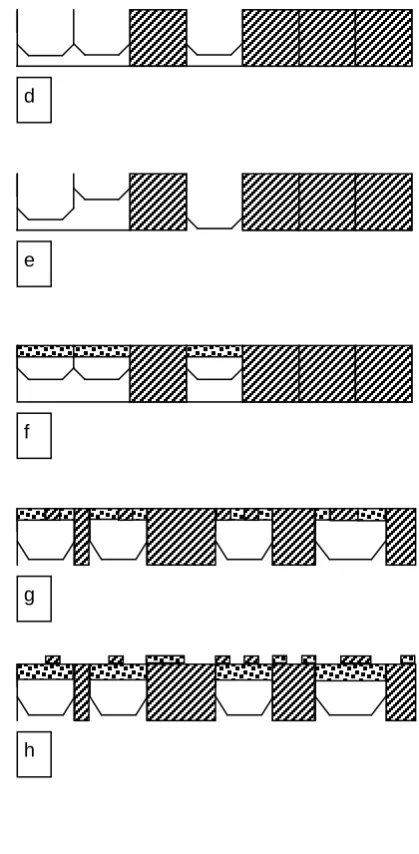
Figures 3d and 3e shows the second prototype active diffuser where a hybrid absorbing-diffusing surface is formed. The concept behind the surfaces is that the impedance discontinuities between the hard and soft patches causes dispersion. The surface causes partial absorption, and any energy that is reflected is diffused13. To maximise this dispersion, the hard and soft patches must be arranged using an optimal pseudo-random sequence. The structures shown are based on an N=7 maximum length sequence which is optimal where ≈50% absorption is to be achieved in a periodic device. (As the device tested only has a single period, strictly speaking a sequence with optimal aperiodic autocorrelation should have been used14). Figure 3a shows an equivalent passive hybrid absorber-diffuser formed from blocks of porous absorbent and hard surfaces. The performance of these types of diffusers are limited in that the best attenuation of the specular reflection lobe is only 6dB at mid-high frequency for a 50% open area device11. This occurs because these devices can not use interference effects to cancel out the specular lobe, all they can do is attenuate the lobe. This problem will not be resolved by the active structure proposed here. The easiest solution to this problem is to shape the surface so it is no longer flat15.
The low frequency performance of passive absorber-diffusers is often limited by the depth of the absorbent that is allowable in the design. Hybrid surfaces cause dispersion at lower frequencies than typical non-absorbing diffusers – because the wavelength of sound in the porous absorbent is lower than in air. Typically these devices are only 2.5cm thick, meaning that diffusion is only significant above about 500Hz. Below that frequency, as the absorption becomes less effective, the attenuation of the specular lobe decreases. By using active devices, it should be possible to extend the performance to lower frequencies by widening the bandwidth of the absorptive patches.
characteristic impedance and the absorption in the active well is done by interference or superposition. Recent developments with active absorption have moved away from the use of superposition, and resistive material is used in combination with active controllers to gain actual dissipation, as shown in Figure 3c. The active controller is then used to maximize the particle velocity through the resistive material and so maximize absorption. This concept was first suggested by Olsen and May4 and Furstoss, Thenail and Galland10 showed that better wideband absorption characteristics could be gained from this approach than using superposition. A concise summary of the development of the hybrid approach is given by Smith et al16. Furstoss et al10 showed that a somewhat better termination criteria is obtained by considering the optimal backing impedance more completely in a transfer matrix approach. However, for the frequency ranges considered here, it was sufficient to drive the pressure to zero at the rear of the absorbent material. This has the advantage of forming a simple controller that can be used either in feedback or feedforward mode.
3.3 Controllers
3.3.1 Schroeder-style diffuser
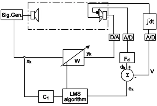
Figure 4 shows an adaptive active control system which has previously been applied to the problem of absorption in ducts and resonant modes in rooms7. The method has been termed active impedance control and relies on the specification of a desired surface impedance at the control source (a conventional electrodynamic loudspeaker driver, shown at the right-hand end of the duct in Figure 4). The difference between the active impedance controller and an archetypal filtered-x LMS control system17 resides in the derivation of the desired signal dk. The control loudspeaker is instrumented
with a microphone and accelerometer; the accelerometer output is then integrated with respect to time giving a signal proportional to cone velocity18,19. Therefore it is possible to directly measure the specific acoustic impedance at the cone surface. Filter Fd acts on the microphone output. The coefficients are
set to give a response equal to the inverse of the desired impedance at the cone – the desired admittance. The output from Fd is therefore the desired velocity dk, which is compared with the actual
velocity in order to derive the error signal ek. Filter C1 contains the plant model, which is 512 tap FIR
filter. The adaptive filter is a 200 tap FIR filter. As with any adaptive filtering, the LMS update gain determines the speed at which the specific acoustic impedance at the cone converges to the value chosen by the specification of Fd. High update gains often cause instability in LMS operations. For the
work on virtual well extensions, the update rate was typically 1x10⁻⁵.
The system was implemented on the Blue Wave PCI/C6600 board incorporating two TMS320C6701 DSP processors. It is shown in feedforward topology. The input xk is driven from the signal generator
which feeds the primary sound sources in the test room. This is a useful regime for developing and testing systems, since ensuring stable operation is straightforward. In the long term, however, this approach is limited as it only works where the primary sound field is generated electroacoustically.
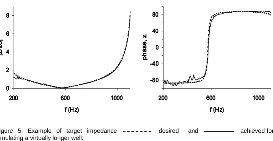
Although the control regime is the same as was used for active absorption in previous studies, the target impedance required to create dispersion without absorption is naturally very different from the impedance required of an active absorber. When the control structure is meant to simulate a virtual extension to the well, the target impedance is given by Equation (2). Unfortunately, the filter Fd, which
contains the target admittance, has singularities when kd = (2m+1)π/2, m=0,1,2,.... This makes it impossible to exactly represent the target admittance. Furthermore, there will be some approximation in representing the target impedance in an appropriate filter structure. In this case, trials showed that an 8 tap IIR filter was found sufficient to represent the target impedance. To overcome the singularity problem, the simulated termination at the bottom of the virtual well is not made infinite, but a large value Xρc is used. Using a transfer matrix approach, it can be shown that this changes the target impedance to:
)
cot(
)
cot(
kd
j
X
c
kd
c
jX
z
(3)singularity was suggested by a reviewer of the paper. The suggestion was to use two separate filters, for both the pressure and the velocity, where the filters could be based on the numerator and denominator of the desired surface impedance.)
The fact that the impedance varies with frequency, means that the velocity and pressure measured by the accelerometer and microphone can change considerably with frequency. This can result in problems whereby the measured signals become inaccurate due to poor signal to noise ratio. Careful setting up of the system is required to avoid this. The target impedance for the hybrid surface using superposition is characteristic impedance.
3.3.2 Hybrid absorber-diffuser
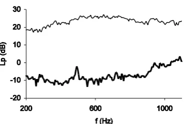
This is the case shown in Figure 3c, with a resistive layer in front of the controller. The desire is to maximise absorption across a broad bandwidth. To achieve this, a microphone is placed behind the absorbent, and the pressure driven to zero in a feedforward configuration, with the pressure being the error signal for the LMS algorithm. This system also works stably in a feedback configuration. The resistive layer was fibre glass and was 3cm thick. Figure 6 shows the pressure behind the resistive material with the controller on and off.
4 Test Environment
In the first instance, the system was developed with the primary source and control surface contained within a single pipe. This enables the control task to be developed in the simplest possible situation. But using this in a real diffuser poses additional problems, for example the scattering from the diffuser surface means the plant model is more complex.
The testing of the full scale diffuser has proven to be logistically difficult. It was decided to construct a 2D world to enable a simple diffuser such as the cross sections shown in Figure 2 to be tested. A full three dimensional diffuser would require multiple controllers to work simultaneously, and it was decided that initially working with one controller would simplify development. The 2D world was formed by placing two large 4m2 boards spaced apart by approximately 10cm. Consequently, the 2D world would be effective up until 1.7kHz before cross modes between the boards would cause problems. (The sampling frequency of the DSP board was therefore set at 3kHz.) It was not possible to test the diffusers in the true far field, because the source and receiver distances became impractical. Instead, the sources and receivers were placed far enough away that a meaningful comparison between the scattering from the passive and active diffusers could be made, and so show that the active diffuser produces the same scattering as the passive equivalent. Tests were done to make sure there was a significant difference in the scattered pressure with and without the control working, and when comparing the diffuser to the flat surface, so the system would be able to tell whether the active controller was working as intended. The disadvantage of this approach is that it doesn‟t show the quality of the scattering produced properly following standards. For instance, it is rare for a narrow diffuser to be used in isolation, and they are normally placed in arrays. To get the true performance and array of the diffusers should be tested, but this was not possible in the 2D world. Consequently, once it has been shown that the active system is scattering as intended in the near field, the intention at this stage is to calculate the far field scattering using a Boundary Element Model as this has been shown to provide accurate predictions of diffuser scattering20.
The source was 1.7m normal to the surface. The receivers were on an arc of radius 1.5m centred on the front of the surface, spaced a little over 5 degrees apart. The polar responses of the scattered sound pressure level were measured using processes similar to that outlined in AES-4id-200121. The results shown are in one-third octave bands.
4.1 Results
4.1.1 Schroeder-style diffuser
In this case the control loudspeaker is being used to simulate a virtual extension to the longest well. Figure 5 shows the target impedance used, both the desired impedance which is embodied in Fd and
impedance when the system was being commissioned in a single duct. A good match between the desired and actual impedance is achieved demonstrating the ability of the system to virtually extend the well depth.
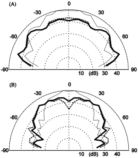
Figure 7 shows polar responses for the diffusers at two frequencies. The polar responses show how the diffusers decrease the energy reflected into the specular reflection direction (normal to the surface) as might be expected. The passive and active surface produce similar scattering, although some differences still exist. This demonstrates that active diffusers can produce scattering as a passive equivalent, but while using a shallower depth.
4.1.2 Hybrid absorber-diffuser
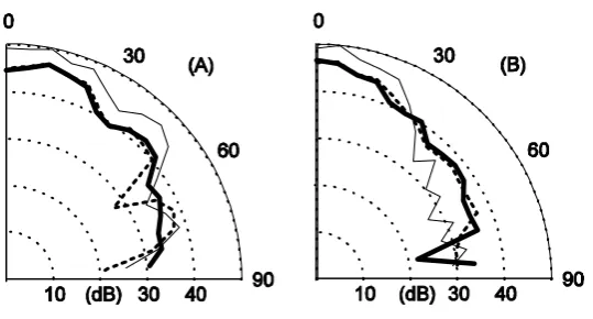
The first case to be tested used the principle of superposition to achieve a well with an impedance of ρc – Figure 3b. Figure 8 shows the impedance achieved at the control surface. Figure 9 shows the scattered polar response for the passive hybrid absorber-diffuser (Figure 3a), the active hybrid absorber-diffuser (Figure 3b) and a plane surface. The active structure is producing the similar scattering to the passive structure, but from a reduced depth.
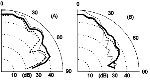
The second case to be tested was where the active diffuser is mounted behind some resistive material – Figure 3c. Figure 6 showed the controlled pressure behind the resistive material. Figure 10 shows the polar responses from the active, passive and plane surface. This again demonstrates that the active diffuser is behaving as expecting and proving the workability of the concept.
5 Discussions
Two structures for hybrid absorber-diffusers have been tested. The construction using some resistive material is probably more useful than the one that purely exploits superposition. There are two reasons: the first is the frequency dependent behaviour of the superposition device and the second is the more easy control task for the device with resistive material.
Consider the device using superposition, Figure 3d. At frequencies higher than those tested here, the active surface would be stationary, and it would be anticipated that active well would appear to be a well of a certain depth with an approximately rigid termination. Consequently, over the frequency range where control can be achieved (from 200Hz to 1.1 kHz in the current implementation), then the device will provide an absorption coefficient of approximately 0.5. Above this frequency range, however, the device will be relatively non-absorbing. Consequently, the superposition device is only useful where absorption and diffusion is limited to low-mid frequencies, and no absorption is required at mid-high frequencies. In the case of small rooms, this could be useful, as additional low-mid frequency absorption is often needed because of the lack of naturally occurring absorptive material for those frequencies. The hybrid surface which places the controller behind some resistive material would produce broadband absorption and diffusion, as at frequencies above where the controller operates, the resistive material will still be an effective porous absorber – there is a complementary relationship between the active and passive elements. Which is more appropriate, an absorber-diffuser with at low frequency only, or a more broadband device depends on what application it is intended for.
The high frequency limit of the hybrid absorber-diffusers will occur when the width of the reflective patches become small compared to wavelength. For the system tested here, the reflective patches were about 10cm wide, and so it might be expected that above 1.7kHz (λ/2=10cm at 1.7kHz) the diffusing ability of the surfaces would decrease. This high frequency limit is rather low, and so methods to overcome this problem are needed. Figures 3g illustrates a proposed solution. A single control surface is used to reduce the pressure behind multiple absorbent patches. The pressure behind each resistive material could be measured and the total of the pressure magnitudes or similar used to drive the LMS algorithm. Alternatively, the rear cavity could be treated as a compliance. In either case, the cavity dimensions would have to remain small compared to wavelengths, so that the system operates below the first mode of the cavity.
diffuser will be in phase, and so the surface reflects in the same way as a plane surface. Recent results have shown that critical frequencies for quadratic residue diffusers create problems over a wider bandwidth than might be expected22. One solution to this would be to stagger the active control surfaces so they are at different depths as shown in Figure 3e. The question this then raises is what is the optimal arrangement of the active elements? It is unlikely that there will be an existing number sequence that can be used, because the number sequence would have to have a large number of zeros within it to account for the zero-depth wells. One solution would be to get a computer to search for a number sequence with optimal autocorrelation properties, with the constraint that the sequence has zeros in it to account for the zero-depth wells. This is commonly done for binary sequences14, and given the small number of wells that need the depth optimizing, this would be relatively easy to do for the case shown in Figure 3e. Alternatively, a simpler approach is suggested based on the need to minimize the effects of critical frequencies. By having the depths related by a a set of relatively prime fractions, e.g.1/2, 1/3, 1/5, 1/7, etc. or even rationals, e.g. 1/2, 3/5, 7/11, etc would be an effective way of ensuring no critical frequencies.
The second reason why the hybrid absorber-diffuser using resistive material is probably better than the superposition case, is that it can be made to work in both feedback and feedforward modes. Active diffusers that are restricted to feedforward operation are only useful in electro-acoustic reproduction. In feedback, the systems can be useful for sound production and reproduction. While the controller in Figure 4 can be adapted to work in feedback mode, for example by the addition of a feedback compensation filter, these do not work across a broad enough bandwidth to be useful for the diffuser application. The simple control task of minimizing the pressure at the rear of the resistive material can work in feedback configuration.
6 Application-realistic simulations
While the performance of hybrid absorber-diffuser surfaces designed to work at mid-high frequencies is fairly well understood, the best design methods for surfaces working down to bass frequencies, as achieved using the active impedances, is not known. So far this paper has examined a single period of a device, which has been rather narrow. This is unrepresentative of real diffuser applications, and when multiple periods of a device are used, the effects of periodicity are as important as the scattering characteristic of a single period of the device. Furthermore, the sources and receivers have not been sufficiently far from the test surface for a proper far field evaluation as is normal practice21. Given that the surface impedances are known, it is possible to predict the scattering from these surfaces using a Boundary Element Model (BEM), and consequently examine how the surfaces will behave in a more application-realistic situation.
This part of the study has concentrated on the hybrid absorber-diffusers. BEMs have been shown to work before for rigid diffusers23, but had not been tested before with room acoustic diffusing surfaces that have significant absorption. Therefore the BEM was validated. A single plane surface shown in Figure 11 was constructed. This was based on a fourth order maximum length sequence, i.e. there were fifteen patches of either absorption or reflection. Each of the fifteen patches was 127mm wide. Absorption was provided by mineral wool 76mm thick, and absorption by varnished wood 25mm thick. The free field polar response was measured in a 2D goniometer following methods prescribed in AES-4id-200121. The BEM was a conventional solution of the Helmholtz-Kirchhoff integral equation11 using a 2D Green‟s function for speed. In this case, 2D models can be used as diffusion is primarily in one plane. For the absorption patches, the impedance was modelled using the Delaney and Bazley empirical formulation24 with a flow resistivity of =50,000 Nm-4 and a porosity of 0.98. Figure 12 shows a typical result from the measurements and predictions at 1.25 kHz. The BEM model agrees well with the measurement allowing further study of these hybrid surfaces by prediction only.
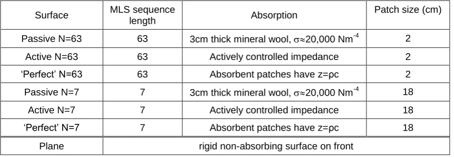
The prediction study used 5 periods of a hybrid absorber-diffuser, with each period being 1.26m wide. Various models were examined as summarized in Table 1. Passive and active diffusers with the same patch configuration are compared. Also considered are diffusers where the absorbent patches offer complete absorption to identify what could be the best dispersion generated by this surface configuration. Two different lengths of MLS sequence were used, primarily to show the effects of patch size on the scattering produced.
low frequency impedance (<1200Hz) was calculated assuming the impedance was zero at the rear of the absorbent (as the pressure had been controlled to zero in this frequency range). Above 1200Hz, the impedance was calculated by assuming the control surface was stationary and presented a rigid termination. This assumption is probably satisfactory, because as the frequency increases, the backing condition becomes less important to the surface impedance and whether controlled or not, the absorbent patches offer a high amount of absorption. The scattering was predicted in the far field and will be displayed as 1/3 octave scattered level polar responses.
6.1 Simulation results
For the surfaces with the narrow patch size (surfaces A and B) the amount of dispersion generated at low-mid frequencies was small. This is shown in Figure 13 where the scattering from the „perfect‟ hybrid device, where the patches are completely absorbing, is shown at two frequencies. At high frequency, the dispersion is reasonable, although the reflection in the specular reflection direction is only attenuated by ≈6dB as is expected for the these flat surfaces with ≈50% open area. At low-mid frequency, the surface only generates absorption, with no additional dispersion. The problem is that when the patch size becomes very much smaller than wavelength, then there is insufficient path length difference between adjacent patches, and consequently the complex array of patches behaves roughly as though it is a single patch with some average absorption. In the case shown in Figure 13A the patches are λ/34 in size, where λ is the wavelength. The solution to this is to increase the patch size.
In Figure 14 the scattering from an active absorber-diffuser is compared to a passive absorber-diffuser and a plane surface. The diffusers have patches that are 18cm across. Below 800 Hz, the active device provides additional absorption when compared to the passive device because of the active controller. At 250Hz, Figure 14a, this causes a general reduction in the energy scattered from the surface. At 500Hz, Figure 14b, the addition of grating lobes generates sideways obliquely propagating sound and so dispersion is being generated. This demonstrated that to generate dispersion from these devices, grating lobes need to be present. This implies a long repeat distance for a periodic device, with the repeat distance being equal to or greater than the wavelength of interest. Above 800Hz, the scattering from the passive and active diffuser are fairly similar as would be expected.
The scattering at the highest frequency tested is shown in Figure 15. This figure shows the effect of patch size on the scattering performance. It would be anticipated that the N=7 device, which has the wider patches, would be worse at high frequency dispersion than the N=63 device which has narrow patches. This is borne out by the results shown in Figure 15.
6.2 Discussion
The performance of hybrid absorber-diffusers designed to work at low frequencies has not been examined in great detail before. The BEM study gives us some incite into how they might be expected to scatter sound, but a more thorough measurement investigation is needed. To achieve dispersion at bass frequencies, patches sizes comparable to a wavelength (or maybe a half wavelength) are needed. Even then the scattering performance is relatively poor. The flat areas of the diffuser create a distinct specular lobe that can only be attenuated by ≈6dB. To improve the scattering performance further, it is necessary to shape the surface (say by bending) to generate additional spatial dispersion. The large patch sizes compromise the high frequency performance somewhat, but this problem can be overcome by adopting a construction inspired by fractals as has been done for Schroeder diffusers25. The surface consists of nested, scaled self-affine diffusers, each of which covers a specific frequency range and offers wide area coverage. Figure 3h shows a suggest form, which has two layers of treatment. The bottom layer is large and so causes wavefront dispersion at low frequencies, the top layer is too small to perturb the large wavelengths. At high frequency, the front layer combines with the rear layer to cause high frequency dispersion. Small reflective elements are placed on the large absorbent patches and thin absorbent patches are placed on the large reflective areas. This structure remains to be tested.
7 Conclusions
Predictions using Boundary Element Methods have examined the broadband, far field performance of these surfaces. While this has demonstrated that the active controllers are working as intended, further work is needed to generate greater dispersion at bass frequencies to better justify the cost and additional complexity inherent in using active designs.
8 Acknowledgements
Table 1. Models tested in BEM study. All were 6.3m wide, 5cm deep, with the sides and rear modelled as being absorbent.
Surface MLS sequence
length Absorption
Patch size (cm)
Passive N=63 63 3cm thick mineral wool, 20,000 Nm-4 2 Active N=63 63 Actively controlled impedance 2 „Perfect‟ N=63 63 Absorbent patches have z=ρc 2 Passive N=7 7 3cm thick mineral wool, 20,000 Nm-4 18
Active N=7 7 Actively controlled impedance 18 „Perfect‟ N=7 7 Absorbent patches have z=ρc 18
Figure Captions
Figure 1 Artist‟s Impression of an active diffuser based on a Schroeder diffuser.
Figure 2. (A) The passive Schroeder diffuser. (B) The active Schroeder diffuser
Figure 3. Possible hybrid absorber-diffusers. (a) A passive device based on an N=7 maximum length sequence. (b) Device measured for this paper using single active controller without absorption in the control well. (c) Device measured for this paper using single active controller with absorption in the control well. h) Various end designs with multiple controlled elements in a period (to be tested), (d-e) using superposition, (f-h) using resistive material.
Figure 4. The controller used for the active impedance wells.
Figure 5. Example of target impedance desired and
achieved for simulating a virtually longer well.
Figure 6. Measured pressure behind resistive material for hybrid absorber-diffuser: controller off, and
controller on.
Figure 7. Measured scattered polar responses for the diffusers shown in Figure 2. (A) 500Hz, (B) 1000Hz.
Passive Schroeder diffuser Active Schroeder diffuser Plane surface
Figure 8.
Desired and
achieved control surface impedance for superposition absorption.
Figure 9. Measured polar response for a hybrid absorber-diffuser using interference in an active well. (A) 500Hz, (B) 1000Hz.
Passive surface Active surface Plane surface
Figure 10. Measured polar response for a hybrid absorber-diffuser using resistive material in an active well. (A) 500Hz, (B) 1000Hz.
Passive surface Active surface Plane surface
Figure 11. The hybrid absorber-diffuser used to test the accuracy of the BEM modelling (dimensions in cm). The shaded sections are constructed of MDF and the unshaded sections of mineral wool.
Figure 12. Comparison of: measured and predicted
scattered pressure level from a hybrid absorber-diffuser. Figure 13 Comparison of predicted scattering from:
„perfect‟ N=63 hybrid absorber-diffuser, and a plane surface.
Figure 14 Comparison of predicted scattering from: Active N=7 hybrid absorber-diffuser, Passive N=7 hybrid absorber-diffuser, and a plane surface.
(A) 250Hz, and (B) 500Hz.
Figures
Figure 2. (A) The passive Schroeder diffuser. (B) The active Schroeder diffuser A
Figure 3. Possible hybrid absorber-diffusers. (a) A passive device based on an N=7 maximum length sequence. (b) Device measured for this paper using single active controller without absorption in the control well. (c) Device measured for this paper using single active controller with absorption in the control well. h) Various end designs with multiple controlled elements in a period (to be tested), (d-e) using superposition, (f-h) using resistive material.
Mineral wool Solid termination
a
b
c
e
f d
g
Figure 7. Measured scattered polar responses for the diffusers shown in Figure 2. (A) 500Hz, (B) 1000Hz.
[image:20.595.70.314.71.349.2]Figure 9. Measured polar response for a hybrid absorber-diffuser using interference in an active well. (A) 500Hz, (B) 1000Hz.
Figure 10. Measured polar response for a hybrid absorber-diffuser using resistive material in an active well. (A) 500Hz, (B) 1000Hz.
Figure 12. Comparison of: measured and predicted
Figure 13 Comparison of predicted scattering from:
„perfect‟ N=63 hybrid absorber-diffuser, and a plane surface.
Figure 14 Comparison of predicted scattering from: Active N=7 hybrid absorber-diffuser, Passive N=7 hybrid absorber-diffuser,and a plane surface.
REFERENCES
1 P.D‟Antonio & T.J.Cox, “Diffusor application in rooms,” Applied Acoustics. 60. 113-142. (2000). 2 M. R. Schroeder, “Binaural dissimilarity and optimum ceilings for concert halls: more lateral sound
diffusion,” J.Acoust.Soc.Am. 65, 958-963 (1979).
3 P. D‟Antonio and T. J. Cox, “Two decades of sound diffusor design and development. part1:
applications and design,” J.Audio.Eng.Soc. 46(11) 955-976. (1998).
4 H. F. Olson & E. G. May, “Electronic sound absorber,”J.Acoust.Soc.Am.25 1130-1136, (1953). 5 P. A. Nelson and S. J. Elliot, ”Active control of sound,” Academic Press, Cambridge, (1995).
6 D. Guiking, K. Karcher, and M. Rollwage, “Coherent active methods for applications in room
acoustics,” J.Acoust.Soc.Am.78 1426-1434, (1985).
7 G. C. Nicholson, “The active control of impedance,” PhD Thesis, University of Salford, (1995). 8 F. Orduna-Bustamante, and P. A. Nelson, “An adaptive controller for the active absorption of sound,”
J.Acoust.Soc.Am. 91 2740-2747, (1992).
9 J. Y. Chung and D. A. Blaser, “Transfer function method of measuring in-duct acousic properties,”
J.Acoust.Soc.Am. 68 907-921, (1980).
10 M. Furstoss, D. Thenail and M. A. Galland, “Surface impedance control for sound absorption: direct
and hybrid passive/active strategies,” J.Sound.Vib. 203(2) 219-236, (1997).
11 T. J. Cox and P. D‟Antonio, “Acoustic Absorbers and Diffusers: Theory, Design and Application,”
Spon Press, (2004).
12
T.J.Cox and P. D'Antonio, “Absorption by surface diffusers,” Proc. I.o.A(UK). Auditorium 2002. London, (2002)
13
J. A. S. Angus, “Sound diffusers using reactive absorption grating,” proc. 98th convention Audio Eng.Soc., preprint 3953, (1995).
14 P. Fan and M. Darnell, “Sequence design for communications applications,” John Wiley and Sons,
49, (1996).
15 T J Cox and P D‟Antonio „Optimized planar and curved diffsorbors‟, 107th Convention of the Audio
Engineering Society, Preprint 5062, Paper D-6, New York (September 1999).
16 J. P. Smith, B. D. Johnson, and R. A. Burdisso, “A broadband passive–active sound absorption
system,” J.Acoust.Soc.Am., 106(5), 2646-2652, (1999).
17 B. Widrow & S.D. Stearns, “Adaptive signal processing,” Prentice Hall, (1985).
18 G. C. Nicholson and P. Darlington, “Smart surfaces for building acoustics,” Proc. IOA 13(8) 155-164,
(1991).
19
G. C. Nicholson and P. Darlington, “Active control of acoustic absorption, reflection and transmission,” Proc.IOA 15(3) 403-409, (1993).
20 T. J. Cox and Y. W. Lam, “Prediction and evaluation of the scattering from quadratic residue
diffusors,” J.Acoust.Soc.Am., 95(1), 297-305, (1994).
21 AES-4id-2001 “AES information document for room acoustics and sound reinforcement systems -
Characterisation and measurement of surface scattering uniformity”. J.Audio.Eng.Soc. 49(3) 149-165. (2001).
22
T J Cox, J A S Angus, P D'Antonio, “The performance of Schroeder Diffusers: a wide band BEM investigation,” Surface Acoustics Symposium, proc. IoA(UK), 25(5) (2003).
23
Predicting the Scattering from Reflectors and Diffusers using 2D Boundary Element Methods. J.Acoust.Soc.Am. 96(2). 874-878. (1994).
24 M. E. Delany and E. N. Bazley, “Acoustical properties of fibrous absorbent materials,” Applied
Acoustics, 3, 105-116, (1970).
25 P. D‟Antonio and J. Konnert, “The QRD diffractal: a new one- or two-dimensional fractal sound