International Journal of Emerging Technology and Advanced Engineering
Website: www.ijetae.com (ISSN 2250-2459,ISO 9001:2008 Certified Journal, Volume 4, Issue 8, August 2014)
15
Free Vibration and Seismic Responses of Power
Transmission Tower Using ANSYS and SAP2000
Huang, Li-Jeng
1, Lin, Yi-Jun
21Associate Professor, Department of Civil Engineering, National Kaohsiung University of Applied Science, 80701, Taiwan,
R.O.C.
2Master Student, Institute of Civil Engineering, National Kaohsiung University of Applied Science, 80701, Taiwan, R.O.C.
Abstract—Power transmission tower is a structure with light weight, high flexibility and low natural frequencies and is sensitive to horizontal loadings, especially the wind and seismic loads. These two kinds of horizontal loads might lead to long-term fatigue or sudden failure and finally cause abnormal condition of power supply. This paper presents dynamic analysis of self-supporting power transmission tower using ANSYS. Based on the finite element method (FEM), we employ Beam-4 element to build the numerical model of the tower. Then typical numerical example is considered and the first leading six fundamental frequencies and periods of the tower crane obtained by ANSYS are obtained and checked by the use of SAP2000. The associated mode shapes obtained from these two softwares are also presented and compared. Furthermore, the time histories of transmission tower frame subjected to 1940 El Centro and 1995 Kobe earthquake are conducted, respectively. Maximal displacements, velocities and accelerations are reported.
Keywords—ANSYS, SAP2000, Power Transmission Tower, Free Vibration, Seismic Responses
I. INTRODUCTION
Electric power transmission towers are important apparatus in modern cities and towns related to energy supply, industrial manufacture and economic development. There are many design types of electric power transmission tower conveying 110 to 750 kV, e.g. self-gravity supported and cable-stayed; among the self-gravity supported types there are a lot of types of shapes. A typical electric power transmission tower employed by Taiwan Electric Company are designed with the following data: 345 KV, Type-B tower with height 36.2 m and base width 11.8m, built with structural members: JIS GB 101 SS55 H, JIS G3101 SS41 H, gusset plate of JIS G3101 5S41, and bolts of ASTM A394,O 11/16 ∮,O 13/16 ∮.
The features of electric power transmission towers are light weight, flexible, low natural frequencies and damping ratios and therefore sensitive to horizontal loads, e.g. wind and earthquake excitations.
Understanding the dynamic characteristics of electric power transmission towers is very important task for the structural engineers when design a power supply system. Basically power transmission towers are designed in a form of space truss structures or space frame structures if members are connected with gusset plates. The total structure is a highly statically in-determinated construction which is stable under self-weight and in general, using L-shape structural steel members and connected by the use of high tension bolts can leads to a strong horizontal drift resisting structure when subjected to wind or earthquake loads. However, a wind loads with Beaufort Number greater than 8 (wind speed ranges 17.2~20.7 m/sec) or seismic excitation with magnitude over 6 might induce instantaneous collapse or long-term fatigue failure.
ASCE Committee (1982, 1991) had reported manual for loadings for electrical transmission structures [1, 2]. Freitas and Ribeiro (1992) conducted elasto-plastic analysis of space truss [3] while Yan et al. (1996) considered geometric nonlinearity [4]. Albermani (2003) studied structural behavior of transmission towers [5]. Li et al. (2004) investigated effect of lines on tower system [6] while Lei and Chien (2005) conducted seismic analysis of transmission towers considering both geometric and material nonlinearities [7], Shi et al. (2006) conducted shaking table tests of Coupled System of Transmission Lines and Tower [8].
International Journal of Emerging Technology and Advanced Engineering
Website: www.ijetae.com (ISSN 2250-2459,ISO 9001:2008 Certified Journal, Volume 4, Issue 8, August 2014)
16
In the study of power transmission towers with large cross-over spans, Li et al. (1990) proposed a simplified calculation of aseismic design of tower-cable coupling system [12]; Li and Wang (1997) studied the dynamic characteristics [13]; Chang et al. (2008) reported the stability and dynamic characteristics of power transmission towers with large span [14]; while Deng et al. (2011) conducted the seismic response of tower-cable system of power transmission towers [15]; Ji et al. (2012) Research on Dynamic Characteristics of the Large Span Transmission Tower-line System [16].However, practical engineers and designers need more information on the dynamic characteristics of the power transmission tower system including static and dynamic behaviours. This paper presents numerical modeling and structural dynamic analysis of a typical tower crane employed in construction engineering. ANSYS and SAP2000 software was employed, respectively, and finite element method is adopted. A typical numerical example of 345KV self-supporting transmission tower was considered, totally 1179 three-dimensional beam elements (BEAM-4 element) along with 495 nodes are employed for modelling the transmission tower structure. Modal analysis was conducted, natural frequencies and vibration modes were studied in detail. In addition, the time histories of transmission tower frame subjected to 1940 El Centro and 1995 Kobe earthquake are conducted, respectively. Maximal displacements, velocities and accelerations are reported and discussed.
II. DYNAMICS MODEL OF A TOWER CRANE FRAME
A. Problem Description
A typical 345 KV self-supporting transmission tower structure is shown in Fig. 1 along with Cartesian coordinate system (x is positive in the right hand direction, y is positive upwards, and z is positive pointed out of plane). The vertical tower frame is with 50 m height and rectangular base with width 10.2 m. For convenience of analysis we isolated the tower structure from the connected power conveying cables.
B. Basic Assumptions
For the structural analysis of the transmission tower frame we employed the following hypotheses:
1.all the members are considered to be three-dimensional thin beams and only flexural and stretching behaviors are included, Euler-Bernoulli assumptions are employed;
2.shear deformation and rotary inertia of members are neglected;
3. damping of system is neglected;
4. all the members are perfectly connected; 5. effect of power conveying cables if isolated;
6. stress-strain relationship of structural members is linearly elastic;
7. tower frame is rigidly connected on the ground.
C. Finite Element Models
In this research we employ ANSYS to build up the finite element model of the transmission tower structure using BEAM-4 element and the results are compared with those obtained from SAP2000.
The displacements in a typical BEAM4 element can be expressed in element local coordinates:
e t q x w N e t x
u( , )} [ ( )]{ ()}
{ (1)
Where t T
x w t w t x w t w e t
q()} { 1(), 1(), 2(), 2()} {
is the
degrees of freedom of each element; and the shape function can be referred to [17].
We can deduce the element inertia matrix, element stiffness matrix and element loading vector, respectively, as
dx w N T w N L e
M e [ ] [ ]
0 ) ( ]
[ (2a)
dx B T B L EI e
K e [ ] [ ]
0 ) ( ]
[ (2b)
dx T w N q L e
f e [ ]
0 ] ) ( }
{ (2c)
Where [B](d2/dx2)[Nw(x)].
D. Dynamic Equations of Transmission Tower System
After assemblage of the element mass and stiffness matrices and loading vectors, we obtain the global systematic matrices and vectors and then enforce the prescribed boundary conditions (e.g. the fixed ends at the bottom of the vertical supporting frames) we can express the equations of motion of the finite element model of the transmission tower as
[M]{x(t)}[K]{x(t)}{f(t)} (3) Where [M] and [K] denotes the global inertia and
International Journal of Emerging Technology and Advanced Engineering
Website: www.ijetae.com (ISSN 2250-2459,ISO 9001:2008 Certified Journal, Volume 4, Issue 8, August 2014)
17
When free vibration is considered, {f(t)}{0}, andunder the assumption of sinusoidal motion, we can obtain the eigen-value system:
(2[M][K]){X}{0} (4)
And the natural frequencies nand vibration modes
n X}
{ , n1,2,N can be obtained. If ANSYS is employed, we can choose sub-space iteration scheme to perform modal analysis to complete the solution.
When seismic responses of transmission tower frame are concerned, the equations of motion can be expressed in matrix form as
)} ( ]{ [ )} ( ]{ [ )} ( ]{
[M xt K xt M ag t (5)
In which ag(t)denotes the ground acceleration.
III. NUMERICAL EXAMPLE AND RESULTS
A. Case Description
We consider a typical transmission tower frame with totally height 50 m and base width 10.2 m, made of the Q345 L-shape structural steel members with the sizes
m m
m 0.127 0.0127 127
.
0 and properties:
. 3 / 7850 , 206 , 4 6 10 703 . 4 , 4 6 10 703 . 4 , 2 0031 . 0 m kg s GPa s E m y I m x I m s A
Totally 1184 BEAM4 elements with 495 degrees of freedom (each member has 6 degrees of freedom) are employed in the ANSYS modelling of transmission tower frame. Overall space frame is fixed onto rigid ground.
B. Free Vibration Analysis
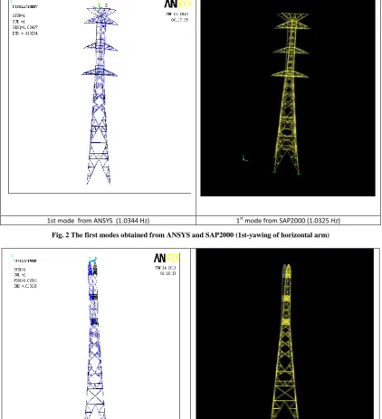
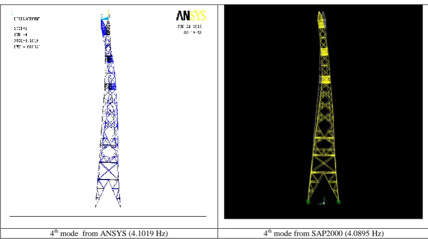
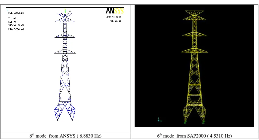
The natural frequencies and corresponding vibration modes of the finite element model of typical tower crane can be obtained using ANSYS and verified by the use of SAP2000. The first leading 6 natural frequencies (f = ω/2π) and natural periods (T=1/f) are summarized in Table 1. The leading 6 natural frequencies range from 1 Hz to 7 Hz.
The corresponding first leading 6 various vibration modes obtained from ANSYS and compared with those obtained from SAP2000 are shown in Fig. 2 to Fig. 7. There appear a lot of interesting different vibration mode shapes considering of pitching, rotation and yawing of overall space frame as well as some combined modes.
Defining the rotation with respect to X-axis, Y-axis and Z-axis to be pitching, rotation and yawing, respectively, we can summarize the leading 6 natural modes of a typical transmission tower frame to be as follows:
(1) 1st-yawing of total tower; (2) 1st-pitching of total tower; (3) 1st-rotating of total tower; (4) 2nd-pitching of total tower; (5) 2nd-rotating of total tower; (6) Symmetrical leg-stretching;
C. Seismic Response Analyses
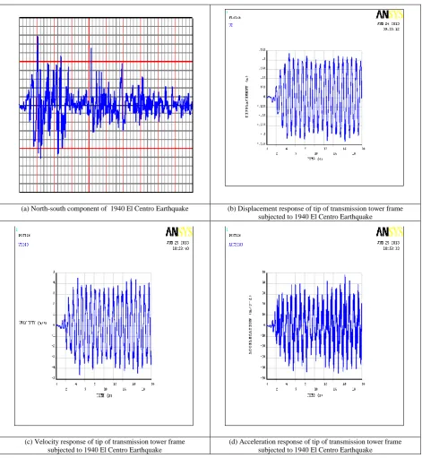
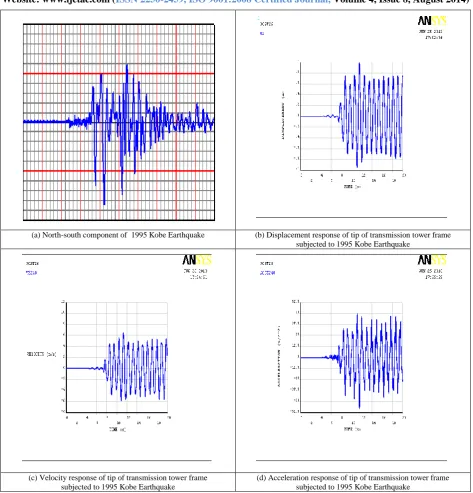
The maximal dynamic responses (displacement, velocity and acceleration) at the tip point (Nodal number No. 240) of transmission tower frame induced by the 1940 El Centro and 1995 Kobe ground accelerations [18] conducted by ANSYS are list in Table II. The time histories of dynamic responses are also shown in the Fig. 8 and Fig. 9, respectively. The results are reasonable.
IV. CONCLUSION
The structural analysis software ANSYS has been successfully applied to analyze the free vibration of a typical power transmission tower frame structure. Three-dimensional BEAM-4 elements are employed in ANSYS. Numerical results show that the leading 6 natural frequencies of this typical transmission tower system range from 1 Hz to 7 Hz. Various vibration modal shapes can be observed and compared with those obtained by SAP2000. Time histories of transmission tower frame subjected to 1940 El Centro and 1995 Kobe earthquake are conducted, respectively. Maximal displacements, velocities and accelerations are also reported.
REFERENCES
[1] ASCE Committee on Electrical Transmission Structures, 1982. Loadings for Electrical Transmission Structures, ASCE, J. Struct. Div., 108(5), 1088-1105.
[2] ASCE, 1991. Guidelines for Electrical Transmission Line Structural Loading, ASCE, Manuals and Reports on Engng Practice, No. 74. [3] J. A. T. De Freitas, and A.C.B.S. Ribeiro, 1992. Large Displacement
Elasto-plastic Analysis of Space Trusses, Int. J. Computers and Structures, 5, 1007-1016.
[4] H. Yan, Y. J. Liu, and D. S. Zhao, 1996. Geometric Nonlinear Analysis of Transmission Tower with Continous Legs, J. Advances in Steel Struct., 5, 339-344.
[5] F. G. Albermani, A, Kitipornchai and S.Numerical, 2003. Simulation of Structural Behavior of Transmission Towers, J. Thin-Walled Struct. 41, 167-177.
International Journal of Emerging Technology and Advanced Engineering
Website: www.ijetae.com (ISSN 2250-2459,ISO 9001:2008 Certified Journal, Volume 4, Issue 8, August 2014)
18
[7] Y. H. Lei and Y. L. Chien, 2005. Seismic Analysis of TransmissionTowers Considering Both Geometric and Material Nonlinearities, Tamkang J. of Sci. and Engng., 8(1), 29-42.
[8] W. L. Shi, H. N. Li, and L. G. Jia, 2006. Shaking Table Test of Coupled System of Transmission Lines and Tower, J. Engng Mech., 23(5), 89-93.
[9] D. S. Chao and S. A. Kin, 2004. Effection of Finite Element Models for Dynamic Characteristics Analysis of Transmission Tower Structure, J. Spec. Struct., 21(3).
[10] B. L. Zhu, W. T. Hu, and C. X. Li, 2006. Estimating seismic responses of transmission towers by finite element method, J. Earth. Engng. and Engng. Vib, 26(5).
[11] L. Luo, B. Y. Liu, and Z. H. Niu, 2010. Research on the Dynamic Properties of Drum-Type Transmission Tower, J. Indus. Archi., S1. [12] H. N. Li, M. Lu and Q. X. Wang, 1990. Simplified Aseismic
Calculation for Large-Span Self-Supporting Transmission Tower System, J. Earth. Engng and Engng Vib, 10(2), 81-89.
[13] H. N. Li and Q. X. Wang, 1997. Dynamic Character of Large-Span Transmission Tower System, J. China Civil Engng, 30(5), 28-36. [14] H. Chang, L. Li, and P. Yin, 2008. Study on Large Span
Transmission Tower Elastic Dynamic Stability under Earthquake, Elect. Power Const., 29(11), 6-11.
[15] H. Z. Deng, R. J. Si, and L. J. Deng, 2011. Seismic Responses of Large Crossing Transmission Tower-line System, J. Vib.. Shock, 30(7), 173-177.
[16] D. M. Ji, D. L. Zhao, X. P. Yao, and G. Q. Bao, 2012. Research on Dynamic Characteristics of the Large Span Transmission Tower-line System, J. Shanghai Univ. Elect. Power, 28(6), 501-504.
[17] E. Hinton and D. R. J. Owen, 1979. An Introduction to Finite Element Computations, Pineridge Press, U.K.
[18] G.. C. Hart and K. Wong, 2000. Structural Dynamics for Structural Engineers, John-Wiley & Sons, Inc.
TABLE I
NATURAL FREQUENCIES AND PERIODS FOR A TYPICAL TRANSMISSION TOWER FRAME
Frequencies (Hz) ANSYS
Frequencies(Hz) SAP2000
Periods (sec)
ANSYS
Periods (sec) SAP2000
Discrepancies (%) ( ( SAP-ANSYS)/ANSYS *100% Mode 1 1.0344 1.0325 0.9667 0.9685 -0.1837
Mode 2 1.0651 1.0655 0.9389 0.9385 0.0376 Mode 3 3.7009 3.6757 0.2702 0.2721 -0.6809 Mode 4 4.1019 4.0894 0.2438 0.2445 -0.3047 Mode 5 5.0381 4.5310 0.1985 0.2207 -10.0653 Mode 6 6.8830 4.8578 0.1453 0.2059 -29.4232
TABLE II
MAXIMAL DYNAMIC RESPONSES OF TRANSMISSION TOWER DUE TO EL CENTRO AND KOBE GROUND ACCELERATION
Ground Acceleration umax
m u
m smax
2
max m s u
International Journal of Emerging Technology and Advanced Engineering
Website: www.ijetae.com (ISSN 2250-2459,ISO 9001:2008 Certified Journal, Volume 4, Issue 8, August 2014)
19
Fig. 1 Schematic of a typical power transmission tower frame using ANSYS and SAP2000 6.38 m
10.4 m
6.88 m
7.45 m
10.2 m
8 m
8 m
4.45
m
26 m
8 m
x
y
z
International Journal of Emerging Technology and Advanced Engineering
Website: www.ijetae.com (ISSN 2250-2459,ISO 9001:2008 Certified Journal, Volume 4, Issue 8, August 2014)
20
[image:6.612.95.518.161.625.2]1st mode from ANSYS (1.0344 Hz) 1st mode from SAP2000 (1.0325 Hz)
Fig. 2 The first modes obtained from ANSYS and SAP2000 (1st-yawing of horizontal arm)
[image:6.612.96.515.423.669.2]2nd mode from ANSYS (1.0651 Hz) 2nd mode from SAP2000 (1.0655 Hz)
International Journal of Emerging Technology and Advanced Engineering
Website: www.ijetae.com (ISSN 2250-2459,ISO 9001:2008 Certified Journal, Volume 4, Issue 8, August 2014)
21
[image:7.612.92.522.154.407.2]3rd mode from ANSYS (3.7009 Hz) 3rd mode from SAP2000 (3.6757 Hz)
Fig. 4 The 3rd modes obtained from ANSYS and SAP2000 (1st-rotating of total tower)
4th mode from ANSYS (4.1019 Hz) 4th mode from SAP2000 (4.0895 Hz)
[image:7.612.94.516.419.654.2]International Journal of Emerging Technology and Advanced Engineering
Website: www.ijetae.com (ISSN 2250-2459,ISO 9001:2008 Certified Journal, Volume 4, Issue 8, August 2014)
22
[image:8.612.92.521.148.419.2]5th mode from ANSYS (5.0381 Hz) 5th mode from SAP2000 ( 4.8578 Hz)
Fig. 6 The 5th modes obtained from ANSYS and SAP2000 (2nd rotating of total tower)
6th mode from ANSYS ( 6.8830 Hz) 6th mode from SAP2000 ( 4.5310 Hz)
[image:8.612.94.519.390.619.2]International Journal of Emerging Technology and Advanced Engineering
Website: www.ijetae.com (ISSN 2250-2459,ISO 9001:2008 Certified Journal, Volume 4, Issue 8, August 2014)
23
(a) North-south component of 1940 El Centro Earthquake (b) Displacement response of tip of transmission tower frame subjected to 1940 El Centro Earthquake
(c) Velocity response of tip of transmission tower frame subjected to 1940 El Centro Earthquake
[image:9.612.71.543.146.658.2](d) Acceleration response of tip of transmission tower frame subjected to 1940 El Centro Earthquake
International Journal of Emerging Technology and Advanced Engineering
Website: www.ijetae.com (ISSN 2250-2459,ISO 9001:2008 Certified Journal, Volume 4, Issue 8, August 2014)
24
(a) North-south component of 1995 Kobe Earthquake (b) Displacement response of tip of transmission tower frame subjected to 1995 Kobe Earthquake
(c) Velocity response of tip of transmission tower frame subjected to 1995 Kobe Earthquake
[image:10.612.70.544.132.626.2](d) Acceleration response of tip of transmission tower frame subjected to 1995 Kobe Earthquake