Technology (IJRASET)
Sliding Mode Control Techique For DC-DC Buck
Converter With Improved Performance
P. Deepak Reddy1 , Dr. Basavaraja Banakar2 1
Research Scholar, Department of EEE GITAM University, Hyderabad Campus, India. 2
Professor & Chairman, E & E Department
University BDT College of Engineering (Constituent college of VTU), Davanagere, Karnataka.
Abstract— This paper presents Sliding Mode controlled, continuous conduction mode buck converter is modelled and a practical sliding mode voltage controller for buck converter operating in continuous conduction mode has been implemented in hardware. Analysis of the sliding mode control for buck converter is explicated. This control technique provides good overall performances and good robustness against load and input voltage variations. Simulation and experimental results are presented.
Keywords— DC-DC converter; sliding mode control; Continuous conduction mode.
I. INTRODUCTION
Electronic power converters are employed as an actuator for electromechanical systems. The buck type DC-DC converters are used in applications where the required output voltage is lower than the source voltage. Different control algorithms are employed to regulate DC-DC converters to achieve a robust output voltage. As DC-DC converters are nonlinear and time variant systems, the application of linear control techniques for the restraint of these converters are not desirable. In order to design a linear control system using classical linear control techniques, the small signal model is derived by linearization around a precise operating point from the state space average model [1]. The controllers based on these techniques are simple to implement, however, it is difficult to account the variation of system parameters, because of the dependence of small signal model parameters on the converter operating point [2]. Variations of system parameters and large signal transients such as those produced at the start up or against changes in the load, cannot be dealt with these techniques. Multiloop control techniques, such as current mode control, have greatly improved the dynamic behavior, but the control design remains difficult especially for higher order converter topologies [3]. A control technique suitable for DC-DC converters must cope with their intrinsic nonlinearity and wide input voltage and load variations, ensuring stability in any operating condition while providing fast transient response. Since switching converters constitute a case of variable structure systems, the sliding mode control technique can be a possible option to control this kind of circuits [4]. The use of sliding mode control enables to improve and even overcome the deficiency of the control method based on small signal models. In particular, sliding mode control improves the dynamic behavior of the system, and becomes very useful when the system is required to operate in the presence of significant unknown disturbances and plant uncertainties [5]. In order to obtain the desired response, the sliding mode technique changes the structure of the controller in response to the changing state of the system. This is realized by the use of a high speed switching control, forcing the trajectory of the system to move to and stay on a predetermined surface which is called sliding surface. The regime of a control system in the sliding surface is called Sliding Mode. In sliding mode a system’s response remains insensitive to parameter variations and disturbances [6]. Unlike other robust schemes, which are computationally intensive linear methods, analogue implementations or digital computation of sliding mode is simple.
II. MODELINGOFBUCKCONVERTER
A. Mathematical Modeling
Technology (IJRASET)
Fig.1 Buck converter.
Therefore, the dynamic equation for the converter designed with the R Load for the circuit topology in is, For continuous conduction mode, The output of the circuit for ON period is,
Fig.2 Buck converter for ON period.
V = L + V (1)
L = − (2)
i = i + i (3)
C + −i = 0 (4)
= + (5)
The output of the circuit for OFF period is: Fig.3 Buck converter for OFF period. L + V = 0 (6)
= (7)
−c − + i = 0 (8)
= − (9)
Technology (IJRASET)
L = uV −V (10)
C = i −i (11)
= 0iftheswitchisatposition0
1iftheswitchisatposition1 (12)
Where iL is the inductor current, Vo or Vcis the output capacitor voltage, VSis the constant external input voltage source, L is the
inductance, C is the capacitance of the output filter and R is the output load resistance. u is the control input taking discrete values of 0 and 1 which represents the switch position. It is assumed here that the inductor current will have a nonzero value due to load variations which is known as the continuous conduction mode (CCM).
Rewriting Equations (10) and (11) in the form of state equations by taking the inductor current and the output capacitor voltage as the states of the system, the following state equations are obtained.
= u− (13)
= − (14)
Where i = (15)
The block diagram of the buck converter using state Equations (12) and (13) is shown in Fig. 4.
Fig.4 Modelling of Buck converter.
B. State Space Modeling
The state space averaging is an approximation technique, which helps in continuous time signal frequency analysis apart from the switching frequency analysis for higher switching frequencies. Though the original system is linear, the resulting system will be non-linear therefore, this averaging technique gives an ease in representation of transfer functions. Thus, from the dynamic equations, the state space equation for the entire switching cycle T is given below, For Continuous mode, In state space form
= 0 Vi +
0 V (16)
V = [0 1] Vi (17)
Technology (IJRASET)
= 0 Vi + 0
0 V (18)
= [0 1] (19)
III. SMC CONTROLTECHNIQUEFORDC-DCBUCKCONVERTER
A control technique suitable for DC-DC converter must match with their nonlinearity and input voltage and load variations, ensuring stability in any operating condition. There are various control techniques such as fuzzy logic, controller, artificial neural network (ANN) controller, sliding mode controller (SMC), PI controller, PID controller, P controller. In this paper sliding mode control method proposed for DC-DC buck converter.
A. System Modeling
Fig.5 Basic structure of an SMVC buck converter.
The voltage error, X1, is
x = V − βV (20)
Where Vref is the constant reference voltage and β = ( ) is the sensing ratio of the output voltage. The rate of change of voltage
error, X2, is
x = ẋ =−β =−β (21)
Where IC = C (dVo/dt) is the capacitor current, and C is the capacitance. Since IC = IL− IR, where IL and IR represent the inductor and
load currents respectively, differentiation of the above equation with respect to time gives
ẋ = ( ) (22)
Using IR = Vo/RL where RL is the load resistance, and the averaged equation of a CCM inductor current.
i =∫ dt (23)
Technology (IJRASET)
˙ ẋ = +
=− + − −u (24)
Finally, from (3.6) and (3.9), a state space model describing the system is derived as
ẋ
ẋ =
0 1
− −
x x +
0
− u +
0
(25)
B. Design Of Sliding Mode Control
In sliding mode control, this control employs a sliding surface to decide its input states, u, to the system. For sliding mode voltage control, the switching states, u, which corresponds the turning on and off of the power converter’s switch, is decided by the sliding line
S =αx + x = Jx = 0 (26)
Where αis a positive quantity (stability condition); J = [α, 1]; and x= [x1 , x2] . It has been derived from that
α= (27)
Graphically, this is simply a straight line on a X1 −X2 phase plane with gradient α However, the implication of α is more than a
‘decision maker’. It actually determines the dynamic response of the system in SM with a first order time constant: τ= . To ensure
that a system follows its sliding surface, a control law must be imposed. In our system, the control law is defined as
Fig.6 Sliding line on X1 – X2 phase-plane.
= 1 = ℎ >
0 = ℎ <− (28)
Equation in accordance with the hitting condition (28), that the system trajectories eventually reach the sliding line. The reason for choosing S > κ and S < −κ as the switching boundary is to introduce an hysteresis band which determines the switching frequency of the converter. If the parameters of the state variables are such that S > κ, switch SW of buck converter shown in Fig. 1 will turn on. Conversely, it will turn off when S < −κ. In the region −κ ≤ S ≤ κ, SW remains in its previous state. Thus, this prevents the SM controller from operating at a frequency that is too high for the power switch to respond. Indirectly, it also alleviates the effect of chattering which could induce extremely high frequency switching. The switching conditions are graphically represented in Fig.6. Next, to ensure that SM control is realizable in this system, an existing condition (26) must be obeyed:
Technology (IJRASET)
Where K1 = and K2 =From the equation, the terms (Vref – βVO) and Ic are the
S = (αx1) + (αx2) = Qx (30)
Where Q = [ α, ]; and X = [X1, X2]T (31)
From (30), S = ( RL) (Vref - βVO) – iC (32)
Equation (32) is known as a sliding surface.
C. Experimental Setup
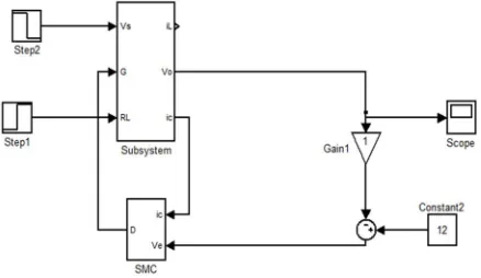
The experimental control setup is described by Fig. 7 and is implemented using the MATLAB/SIMULINK software.
IV. SIMULATION RESULTS
The parameters of the simulated Buck converter were as follows: Vin = 45V to 48V, Vout = 12V, L = 0.1mH, C = 0.002uF. Fig.9
shows the response of a Buck converter undergoing the input voltage step change from 45V to 48V, load resistance step change 3 ohm to 6 ohm, was simulated. Fig. 12 shows the output voltage ripple waveform of the buck converter operating at load when the input voltage varied from 48 V to 45V at variable high frequency. This was performed to test the robustness of the converter to a slowly varying input voltage. In Fig.12 it is found that the ripple content in output voltage is 0.1% and in Fig.13 the ripple content in load current is 3.3%. Fig.9 to Fig.11 prove the robustness of the sliding mode control against changes in the load and variations in the input voltage. In Fig.15 Practical hardware model is developed in closed loop for buck converter. The parameters of the experimental Buck converter were as follows: Vin = 13V, Vout = 7.2V.
[image:7.612.192.411.441.568.2]Technology (IJRASET)
Fig. 9 Step change of input voltage and load resistance and the waveform of output voltage.
Fig.10 The output voltage and load current waveforms for Step change of input voltage and load resistance.
Technology (IJRASET)
[image:9.612.198.406.91.273.2]Fig.12 Ripple content in output voltage.
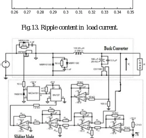
Fig.13. Ripple content in load current.
Fig. 14 Full schematic diagram of the SMVC buck converter prototype.
0.039 0.0395 0.04 0.0405 0.041 0.0415
11.995 12 12.005 12.01
0.26 0.27 0.28 0.29 0.3 0.31 0.32 0.33 0.34 0.35
[image:9.612.194.429.466.688.2]Technology (IJRASET)
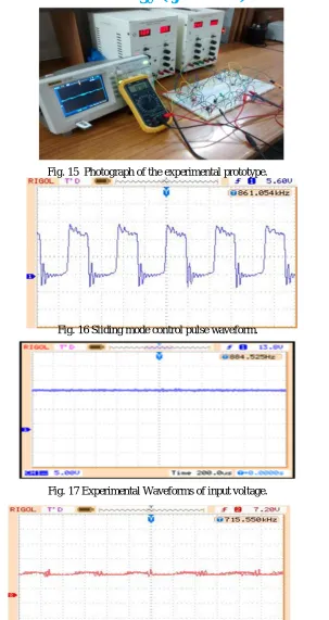
Fig. 15 Photograph of the experimental prototype.
Fig. 16 Sliding mode control pulse waveform.
Fig. 17 Experimental Waveforms of input voltage.
Fig. 18 Experimental Waveforms of output voltage.
V. CONCLUSION
Technology (IJRASET)
converter has been implemented in hardware. Simulation and experimental results are provided, which will verify the theoretical analysis. This paper provides a way to better understand the SM control technique, and is helpful for the application of DC-DC converters operating in CCM.
REFERENCES
[1] A. J. Forsyth, “Modeling and Control of DC-DC Converters,” Power Engineering Journal, Vol. 12, No. 5, 1998, pp. 229-236.doi:10.1049/pe:19980507
[2] P. Mattavelli, L. Rosetto and G. Spiazzi, “Small-Signal Analysis of Dc-Dc Converters with Sliding Mode Control,” IEEE Transactions on Power Electronics,
Vol. 12, No. 1, 1997, pp. 96-102. doi:10.1109/63.554174
[3] J. Matas, L. G. Vicuna, O. Lopez, M. Lopez and M. Castilla, “Sliding-LQR Based Control of Dc-Dc Converters,” European Power Electronics Conference
(EPE’99), Lausanne, 7-9 September 1999.
[4] G. Spiazzi and P. Mattavelli, “Sliding Mode Control of Switched-Mode Power Supplies,” CRC Press LLC, Boca Raton, 2002.
[5] O. Kaynak and F. Harashima, “Disturbance Rejection by Means of Sliding Mode,” IEEE Transactions on Industrial Applications, Vol. 32, No. 1, 1985, pp.
85-87.
[6] Y. He and F. L. Luo, “Sliding-Mode Control for Dc-Dc Converters with Constant Switching Frequency,” Control Theory and Applications, Vol. 153, No. 16,
2006, pp. 37- 45.
[7] Z. H. Akpolat and H. Guldemir, “Trajectory Following Sliding Mode Control of Induction Motors,” Electrical Engineering, Vol. 85, No. 4, 2003, pp. 205-209.
doi:10.1007/s00202-003-0166-6
[8] H. Guldemir, “Sliding Mode Speed Control for Dc Drive Systems,” Mathematical and Computational Applications, Vol. 8, 2003, pp. 337-384.
[9] H. Guldemir, “Sliding Mode Control of Dc-Dc Boost Converter,” Journal of Applied Sciences, Vol. 5, No. 3, 2005, pp. 588- 592.
[10] J. J. Slotine and T. S. Liu, “Applied Nonlinear Control,” Prentice Hall, Englewood Cliffs, 1991.
[11] J. Y. Hung, W. Gao and J. C. Hung, “Variable Structure Control: A Survey,” IEEE Transactions on Industrial Electronics, Vol. 40, No. 1, 1993, pp. 2-21.
doi:10.1109/41.184817.
[12] V. Utkin, J. Guldner and J. Shi, “Sliding Mode Control in Electromechanical Systems,” Taylor and Francis, London, 1999.
[13] V. Utkin, “Sliding Mode Control Design Principles and Applications to Electric Drives,” IEEE Transactions on Industrial Applications, Vol. 40, 1993, pp.
23-36.
[14] J. H. Su, J. J. Chen and D. S. Wu, “Learning Feedback. Controller Design of Switching Converters via Matlab/ Simulink,” IEEE Transactions on Education,
Vol. 45, 2002, pp. 307-315. doi:10.1109/TE.2002.803403.
[15] H. Sira-Ramirez, “On the Generalized PI Sliding Mode Control of DC to DC Power Converters: A Tutorial,” International Journal of Control, Vol. 76, No. 9,