6
I
January 2018
A Three-Dimensional Fea Model of a Catalytic Plug
for Alternative Fuels
Mr.V.Karthikeyan1, Mr. Akhil K Nair2, Mr. B.Vignesh3, Mr. S. Arun Raj4, Mr. M.Karthi5 1
Assistant Professor, 2, 3, 4, 5 Final year Department of Mechanical Engineering,
Abstract: Aquanol which is a blend of 70% ethanol and 30% water is used as fuel in our testing. This fuel reduces the NOx emissions from the engine. Existing spark plugs cannot produce spark intensity high enough to ignite the aquanol fuel. The plug’s core is an alumina rod over which platinum wire of 0.45mm diameter is wound. When electrical connection is provided to
the wire, it turns red hot reaching a temperature of around 850o Celsius. When the aquanol and air mixture comes in contact
with the red hot wire, the fuel mixture gets ignited. Also the catalytic core material dimensions were optimized by using ANSYS Coupled-Field analysis and the Catalytic Plug has fabricated according to the results obtained. The Catalytic Plug was tested by varying the variables like input power, wire diameter and fluid velocity, the corresponding temperature distribution was obtained. Thus, this catalytic plug can be boon to the future of alternate fuels.
Keywords: aquanol, alternate fuel, coupled-field, catalytic plug
I. INTRODUCTION
Recent studies have conveyed that by the year 2020, all conventional fuels (fossil fuels) will get depleted. So, there is an ever growing need to develop alternate fuels to cater to the needs of the thirsty industries. The ultimate aim of the research is use the Aquanol as an alternative fuel for diesel engines. Existing research results shows that “ethanol” is the best alternate fuel. Self-ignition temperature for ethanol and Aquanol is greater than that of petrol and diesel. So, we need a high intensity igniter plug made of catalytic material for ignite the fuel and for the better performance. This is achieved by the “Catalytic plug”.
A. Alcohols
As said earlier alcohols are the most abundant and promising substitute for fossil fuels. Methanol or methyl alcohol can be made from coal, a relatively abundant fossil fuel. Ethanol or ethyl alcohol can be produced by fermentation of carbohydrates which occur naturally and abundantly in some plants like sugarcane, potatoes, corn etc. hence these fuels can be made from highly reliable and long lasting raw material sources.
It has been known since the invention of the internal combustion engines that alcohols could be used as motor fuel. Since World War II the user of alcohol as a motor fuel has been reduced to less than one tenth of the pre World War II levels except for countries like Brazil, Venezuela, and Cuba… where there is large supply of sugarcane.
Since ethanol and methanol have higher self ignition temperature compared to the existing conventional fuels, we need to develop a high intensity spark to ignite these fuels. The existing spark plugs to develop necessary temperature to ignite the fuel the central electrode can be coated with Platinum by using plasma spray coating.
B. Problems With Alcohol Fuels
The major problem encountered with alcohol fuels in diesel engines is its poor cold start ability together with the unstable combustion levels under low loads. Forced ignition techniques such as glow plugs and spark plugs have been used to overcome these problems. The major disadvantages with use of these glow plugs are their high power requirements and limited life time. This low lifetime can be overcome by catalytically igniting alcohols with the use of platinum and platinum/rhodium coated glow plugs. . Previous research on catalytic igniters and aqueous fueled engines showed potential for lowering emissions and increasing engine efficiency over conventional engine configurations. Catalysts do not only increase the rate at which chemical reactions ( combustions, in this case) take place but also decrease the minimum temperatures required (when compared to steel alloy glow plugs) thus increasing the life time of glow plugs as well as reducing their energy requirements for proper operation.
trees (bio mass) has indicated a potential for favorable net yields of energy use of renewable bio mass as feedstock’s for ethanol production can decrease the carbon mono oxide emissions
With ethanol, compared to diesel engines at the same compression ratio, engine thermal efficiency increases by 4%, peak nitrogen oxide emissions decreased 50%, unburned fuel and carbon mono oxide emissions were decreased, and aldehyde emissions increased. As the compression ratio increases aldehyde emissions increase due to the fact that high compression ratios may result from reduced exhaust temperatures. As exhaust temperatures decreases, oxidation of aldehydes in the exhaust system decreases.
Table: 1 Fuel Properties
PROPERTY DIESEL GASOLINE ETHANOL
Boiling point [K] 461-616 300-498 351
Auto ignition temperature [K] 589 530 696
Stochiometric air/fuel ratio [wt. /wt.] 14.6 14.5 9
Rich flammability limit [vol.
Percent] 7.6 6 19
Lean flammability limit [vol.
percent] 1.4 1 4.3
Lower heating value [MJ/KG] 43.2 44 26.9
Aquanol is environmentally friendly and cost-effective than current alternate fuels. “Wet” alcohol fuels have much lower combustion temperatures than pure alcohol fuels or gasoline. This is the primary reason that aqueous fuels have such low NOx emissions. The reduced temperatures also ensure that the catalytic materials do not degraded during the combustion process. This is important for extended life of catalytic igniters. Lowered combustion temperatures do not adversely affect the engine efficiency. Aquanol is environmentally friendly in another important way. Accidental spills biodegrade rapidly in comparison to petroleum-derived fuels and expensive remediation of spill sites is avoided. For this reason, aquanol is likely to become a preferred fuel for watercraft.
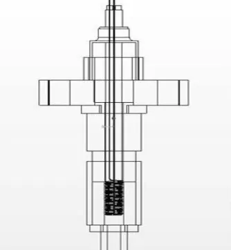
C. Fabrication Of The Catalytic Plug
Fuel injector was bought and the necessary modifications were done. Central tapered hole is made as 8.5 mm dia through hole, which is the diameter of the alumina rod (Al2 O3). Platinum-rhodium (Rh-13%) alloy wire of length 500 mm and 0.45mm dia is wound around the alumina rod up to a height of 20 mm. This rod-wire setup is placed inside the central hole of the injector.
[image:3.612.225.392.536.717.2]The central core (Alumina rod Pt-Rh wire) is aligned to the center position of the injector body and sealed. Sealing is done by mixture of sodium silicate liquid and bonding cement. This mixture is heat resistant, non conductor of electricity and also acts as a gas seal. After applying this paste, the plug is allowed to set, and then by 24 hours of setting, the plug is heated in a gas flame. The arrangement is shown in the figure.1.
The catalytic plug is a self contained ignition system that may be retro-fitted to existing spark-ignition and compression–ignition engines. The catalytic plug consists of a ceramic rod, over that the platinum and rhodium catalyst wire has wound up to two centimeter length. Because of the platinum is having high melting point up to 1769°C, acting as a good conductor and also produces high temperature up to 950°C while supplying 12V supply. The Rhodium is added with the platinum to increase the ductility, so as to wound the wire easily on the rod. The various properties of the Nobel metals used for this purpose are shown in the Table.2. Cold starting requires up to 25 watts/igniter from an external power source (12 volt), which is no longer necessary after a few minutes of operation at idle.
[image:4.612.34.579.274.386.2]The catalytic core is enclosed in a gun metal shell that forms a part of the pre-chamber adjacent to the combustion chamber. Adjusting the location of the catalyst section on the ceramic rod controls ignition timing. To affect the ignition advance, the catalyst probe must be moved closer to the nozzles. Use of catalytic plug technology allows the combustion of very lean fuel/air mixtures in the presence of water vapor. The outer body of the igniter must be machined to match the combustion chamber opening. At present, the process of fabricating the internal parts of the igniter is labor intensive. Platinum wire must be precision wound onto the ceramic rod and several miniature electrical connections must be made.
Table 2 Properties Of Nobel Metals
Material And Diameter Resistance Of The Wire For Length(20Cm)
Voltage Obtained
Time For Red Hot Condition
Temperature At Red Hot Condition
Nichrome 0.3 mm
dia(40%Ni) 6.5Ω 7mV 4 seconds 150°C
Nichrome 0.45 mm
dia(60%Ni) 3 Ω 17mV 5 seconds 352°C
Silver 0.3mm dia 7.3 Ω 5mV 2 seconds 114°C
Silver 0.45mm dia 5 Ω 10mV 3 seconds 204°C
D. Testing Of Platinum wire
The platinum wire wound around the alumina rod is given 12V supply through the battery. The wire became red hot. Time taken to become red hot is 3 seconds. The temperature is measured using the iron constant thermocouple. The output is obtained in millivolts by a multimeter. The temperature corresponding to these millivolts is interpreted from the voltage-temperature graph. Over this red hot platinum wire ethanol fuel is sprayed. The fuel got burnt and flames were observed. The electrical resistance of platinum varies as R = Ro [1 + α (T -To) ] where R is the electrical resistance at temperature T, Ro is the electrical resistance at temperature To, and
α is the coefficient of resistance for Pt, a property of the metal. With the Pt wire connected to a variable power supply and with voltage monitored separately, power to the wire was slowly increased as a propane-air mixture was passed over it. When surface reactions began, the temperature of the wire increased abruptly as indicated by a sudden change in voltage. The corresponding change in resistance was calculated and the average wire temperature found from the equation above. The average temperature obtained at the power level where surface reactions began was used for comparison with the flow finite element (FEA) model results. Platinum is one of the best conductors of heat and electricity. It also resists chemical corrosion and electrical erosion much better than steel alloys, making it an ideal material for the spark plug electrode(s). Some plugs have a solid platinum center electrode while others have a small.
Table 3 Wires And Temperatures
MATERIAL PROPERTY PLATINUM PALLADIUM RHODIUM STAINLESS STEEL
Hardness 250BHN 109BHN 390BHN 185BHN
Melting point °C 1769 1554 1966 1370
availability Moderate abundant rare Abundant
draw ability Good Very good poor Good
machinability Fair fair less Fair
cost Costly costly Very costly cheap
[image:4.612.33.580.608.707.2]The main reason for using platinum electrodes is to minimize electrode wear. Every time a plug fires, a tiny amount of metal is vaporized and lost from the surface of both electrodes. The center electrode typically suffers the most wear because it runs hotter than the side electrode.
Using platinum almost eliminates electrode wear. Platinum is expensive, but it can double or even triple a spark plug's normal service life - from 30,000 to 45,000 miles for a standard plug up to 60,000 to 100,000 miles or more with platinum
E. Analysis
The temperature over a platinum wire surface was calculated using thermocouple. Experimental results were compared with predictions from a steady-flow finite element (FEA) model. The average catalyst wire temperatures obtained from three-dimensional FEA models over predicted the experimentally obtained temperatures by 6 percent. Modeling assumptions (prescribed end temperatures of the wire and negligible thermal radiation) and uncertainty in the convective heat transfer coefficient contributed to the differences between model and data.
The FEA analysis indicated that axial conduction dominated heat losses from the Pt catalyst in comparison with radial convection. This finding suggested that thermal breaks and/or substrates with lower thermal conductivity will reduce heat losses from catalytic igniters.
[image:5.612.170.444.315.467.2]FEA Analysis was done by using the ANSYS coupled field analysis. This analysis is carried out by varying the wire diameter and the power input, the results are recorded. The temperature over the surface of the coil has found for various values of power input and wire diameter. The meshed model used for the analysis is shown in the Figure.2.
Figure 2 Meshed model (Platinum wire wound over the Ceramic rod)
F. Findings And Conclusion
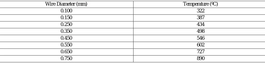
Studies were conducted to investigate the changes in the average wire temperature with corresponding changes in the wire diameter (Table 4). The results indicate that higher average catalyst temperatures were obtained for thicker wires and the catalyst temperature decreases as we used thinner wires. This is due to the fact that axial conduction dominates radial convection.
Table 4 Effect Of Change In Wire Diameter On Average Catalyst Temperature
Wire Diameter (mm) Temperature (ºC)
0.100 322
0.150 387
0.250 434
0.350 498
0.450 546
0.550 602
0.650 727
0.750 890
[image:5.612.37.572.574.701.2]Table 5 Effect Of Power Input On Average Catalyst Temperature
Power Input(W) Temperature (ºC)
0.75 280
0.79 344
0.83 402
0.88 486
0.96 557
1.06 642
1.20 731
1.28 825
The results show an increase in average catalyst temperature with the changes in the power supply. As the heat input to the system increases, the average catalyst temperature increases. In the laboratory experiments we observed a similar trend. The average temperature obtained at the power level where surface reactions began using this three-dimensional analysis is 825 ºC that is 8 percent higher than the experimental average temperature.
Differences between experiment and model may be due to modeling assumptions (the end temperature of the wire is prescribed and thermal radiation is neglected) and uncertainty in the convective heat transfer coefficient. It indicates that physical assumptions such as a prescribed top surface temperature and negligible thermal radiation, and uncertainties in the convective heat transfer coefficient are critical for matching experimental conditions.
II. FUTURE WORK
Future work will determine the threshold-heating rate of the Pt wire at which the ignition of aqueous ethanol fuel-air mixtures occurs. This work is expected to support design improvements for catalytic igniters to help alleviate cold starting problems.
The FEA modeling indicates that thermal breaks and/or substrates with lower thermal conductivity will reduce heat losses from catalytic igniters, a concern during cold start. Our new ability to model detailed combustion kinetics permits us to determine the optimal ignition and combustion conditions needed to reduce the formation of toxins and environmental contaminants from renewable transportation fuels.
In this analysis, the heat dissipated to the surroundings through radiation is not counted. If it will count, then the error percentage can be minimized.
REFERENCES
[1] Cordon, D., E. Clarke, S. Beyerlein, J. Steciak, and M. Cherry, “Catalytic igniter to support combustion of ethanol-water/air mixtures in internal combustion engines,”
[2] Gottschalk, Mark A., “Catalytic ignition replaces spark plugs.”
[3] Jehlik, F., M. M. Jones, P. Shepherd, J. Norbeck, K. Johnson, and M. McClanahan, “Development of a low-emission, dedicated ethanol-fuel vehicle with cold-start distillation system.”
[4] Karim, H., L. D. Pfefferle, P. Markatou and M.Smooke, “Modeling heterogeneous/ homogeneous reactions and transport coupling of catalytic combustion of methyl chloride over a Mn-based catalyst.
[5] Mitchell, W. L., T. A. Litzinger, and W.Lee, “Effects of in-cylinder catalysts on combustion and emissions of a D.I. diesel engine fueled on methanol.” [6] Borisov, A. A., V. M. Zamanskii, A. A., Konnov, V. V., Lisyanskii, S. A., Rusakov, and G. G. I. Skachkov, “A mechanism of high-temperature ethanol
ignition.
[7] Cherry, M. A., “Catalytic-compression timed ignition.” [8] Cherry, M., “Catalytic-Compression Timed Ignition.”