www.ijsrp.org
Comparative analysis of rectangular and triangular
cylindrical microstrip patch antenna
Esha Johari
1, Hardesh Kumar Singh
2, Sovan Mohanthy
3, Dr. Pradyot Kala
41,2,3
Department of ECE, SRMSCET Bareilly U.P. ,4Department of ECE, PDM College of Engineering Haryana
1
[email protected],[email protected],[email protected]
4
Abstract- The objective of this paper is to develop a comparative analysis of rectangular and triangular cylindrical microstrip patch antenna. In this study we would like to take into account the problems of resonance and radiation of cylindrical rectangular and triangular microstrip patch antenna. Design procedure involves parameters related to cylindrical microstrip elements to realize the desired resonant frequency, input impedance, radiation patterns etc. Transmission line model is used to calculate the input impedance of the patch, while cavity model is used to calculate its radiation pattern. For a cylindrical-rectangular microstrip antenna, it is observed that the beam-width, resonant frequency, and resonant resistance decrease with cylinder radius. The bandwidth is not sensitive to curvature but it decreases as substrate permittivity increases. Triangular microstrip antennas are a good substitute for rectangular microstrip antennas, especially in microstrip array designs, due to their similar radiation properties and because the triangular patch is physically smaller than the rectangular patch
Index Terms- Cylindrical-rectangular patch, cavity model, conformal antenna, conformal mapping
I. INTRODUCTION
s microstrip antennas are low profile antenna, one of the major advantages of microstrip antennas is that they can be made conformal to the surfaces on which they are mounted. A conformable antenna on a regular surface viz. cylindrical surface is easily achievable by conforming microstrip patch antenna on the surface. However the majority of the studies proposed in this area have been concentrated on rectangular and circular microstrip antennas. Mainly the triangular patch antenna has radiation properties similar to that of the rectangular antenna, with the advantage of being physically smaller. Rectangular and triangular type of radiating microstrip patch antenna mounted, as considered in this paper, on a cylindrical surface is chosen because major real world shapes can be approximated by cylindrical surface or cylindrical sector and uniformity in a plane provide ease of analysis.
This structure was first proposed by Krowne[1]. Using a cavity model, he observed that resonant frequency changes with surface curvature. Wu et al [2], calculated the radiation patterns using cavity model in conjunction with the method of images, but this method is not applicable when the ground plane is not flat. Fonseca and Giarola [3], the radiation from the wraparound cylindrical microstrip element was computed from a magnetic wall cavity model. Luk et al. [4], considered the case when the substrate thickness is much smaller than the wavelength and the
radius of curvature.Based on the cavity model, they found that the resonant frequencies and electric field under the patch were not affected by curvature. Kin-Lu Wong and Shan-Cheng Pan in 1997 again found the complex resonant frequencies of the cylindrical triangular microstrip patch are obtained. The real and imaginary parts of the complex resonant frequency give the resonant frequency and radiation loss of the structure. Mainly full wave analysis is applied to cylindrical microstrip patch antenna [6]-[7].At that time, method of moments (MoM), transmission line model is frequently used to analyze the patch fabricated on cylindrical substrate.
A comparative study of rectangular and triangular patch antenna may lead to new dimensions and types of conformal antenna. Due to their smaller size and high bandwidth, a triangular patch antenna (TPA) is already in demand in planar antenna structure. The purpose of this paper is to make a comparative study of two types of non planar antenna in order to show the advantages of triangular patch antenna on curved surfaces.
II THEORETICAL FORMULATION
A. CYLINDRICAL RECTANGULAR PATCH ANTENNA
The basic design of cylindrical rectangular patch antenna is as shown in figure 1. The dimension of the straight edge is 2b and for curved edge is 2(a + h) θ1, where a, radius of cylindrical ground plane and 2θ1 the angle subtended by the curved edge. The fundamental mode TM01 (to the ρ direction) is considered, the patch is excited in the direction along with the cylinder axis. The conducting patch and ground cylinder is treated as electric and magnetic field of cavity, determined by dropping perpendiculars from the patch edges to the cylindrical conducting surface.
www.ijsrp.org
A.1 Resonant frequency: Krowne in 1983[1], theoretically
calculated and make a comparative analysis between planar resonant and cylindrical resonant frequency (frR and frC). The results demonstrate that assumption (h<<a) is good and that it is excellent when considering excitation of the antenna with no spatial field variation normal to the surface Using cylindrical coordinates, the electric field satisfies the wave equation:
ρ
(ρ ) ρ ρ
ρ
ρ
ρ ρ
Where k2= ω2με
Using approximation h<<a, assuming ρ = a + h, the eigen functions of Eρ and eigen values of k is given by:
Eρ= ψmn = [
]
k2 = k2mn = (
) (
)
The expression for kmn and ψmn represent the field distribution and wave number of TMmn excitation. The equivalent magnetic
currents along the edges of the curved patch are obtained from M = Eρ (ρ x n)
Far field of these magnetic currents for TM10 and TM01 modes is given by following equations:
TM10 mode
:
(
)
θ
θ
θ
∑ ερρ θ θ [ ( )]
Eθ ≈ 0
TM01 mode:
Eθ
( ) ( √ )
∑ [ ( )]
E ≈ 0
Both TM01 and TM10 modes are highly sensitive to curvature effects of cylinder and thus the resonant frequency.
The expression for the resonant frequencies is
fmn = √ [( ) ( ) ]
It concludes that if dimensions 2 (a+h) θ1 and 2b of the patch are fixed, then the resonant frequency of TM10 modes are not affected by curvature.
A. 2Input impedance: Curved patch is excited by a coax feed at
z =- z’, = ’. The feed is modeled by a current ribbon of effective arc of length, w. The input impedance is obtained by evaluating the integral:
∫
The result thus obtained is given by:
∑ ∑ ε
θ [
]
[ θ ]
( θ ) ( ) ( )
Where,
={
, {
eff is the effective loss tangent.
B. CYLINDRICAL TRIANGULAR PATCH ANTENNA
www.ijsrp.org Fig.2 The geometry of a cylindrical triangular microstrip patch antenna
The relation between d1 and d2 is given by:
=√( ) (9)
Where dh is the distance from the tip to bottom of the triangle. For analysis of triangular patch antenna only one expansion basis function for the unknown surface patch antenna is assumed, given by:
[ ]
[ ]
Where2dh is the distance from the tip to bottom side (length 2b o) of the triangle.
B.1Resonant Frequency: By using full-wave analysis,
homogenous matrix equation is obtained [8], given by:
[
] [ ] (12)
Where, elements of z matrix can be found by evaluating eq (11).By solving |z|, resonant frequency and radiation loss of cylindrical triangular microstrip patch is obtained.
III RESULTS ANALYSIS
Since the input impedance of both type of antenna is affected by the curvature of patch antenna, the 50 Ω input impedance is maintained and the impedance matching to 50 Ω coax is maintained [5].A rectangular patch is fabricated on a flexible substrate (RO3003) with εr=2.98 and h=0.762 mm. Figure 3 shows the input impedance variation with frequency having
coaxial feed point at (90o, 0.93cm).From the reactance curve, resonant frequency at 1435 MHz is obtained.
Fig.3 Input impedance calculated versus frequency for various cylinder radii. Radiation pattern in (y-z) and (x-y) planes are plotted defining the E-plane and H-plane respectively. In Fig 4(a) E-plane pattern shows superstrate loading causes decrement in 3-dB bandwidth with increasing superstrate thickness and cylinder radius.
(a)
www.ijsrp.org (b)
Fig. 4 Radiation pattern calculated at resonance for rectangular patch (a) E-plane, (b) H-plane
A triangular patch is fabricated on a flexible substrate with εr=3.0 and h = 0.762 mm. The geometry of patch includes d1=d2=7.18cm.The other design parameters are as discussed below:
Parameter Value
2L 6 cm
2b o 4 cm
( p, zp) (90o,0.93 cm)
a 8 cm
The input impedance variation is as shown in Fig 5.Resonant frequency thus obtained from the curve be 1905MHz. Fig shows that resonant frequency increases with decreasing cylinder radius.
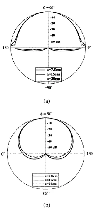
Fig. 5 Input impedance measured at TM01 mode versus frequency The results plotted for radiation pattern, Fig 6 indicates that with decreasing cylinder radius, both E-plane and H-plane are slightly broadened and radiation is increased in backward direction.
(a)
[image:4.612.45.293.55.223.2](b)
Fig. 6 Radiation pattern calculated at resonance for triangular patch (a) E-plane, (b) H-plane
IV CONCLUSION
From the comparative analysis of rectangular and triangular microstrip patch antenna it can be conclude that TPA can be a good substitute for rectangular patch, due to its physical smaller size. As the most outstanding drawback of conformal antenna is its increased complexity and cost of designing. TPA can be used to overcome this drawback. Radiation patterns are obtained at resonant frequency of TM10 mode for different values of a [9].TPA mounted on a cylindrical body of smaller radius has better linear polarization characteristics. Controlling polarization properties of microstrip antenna is another area of development due to need of making greater use of polarization properties of waves in radars. As the TPA shows good linear polarization characteristics, it can be advantageous for avionics application in future. Array configurations of conformal antennas would be the next step for the general conformal antenna study [13].
[image:4.612.55.278.440.580.2]www.ijsrp.org spherical and toroidal structures [14]. A toroidal microstrip
antenna is analyzed as a quasi-omnidirectional conformal antenna.
REFERENCES
[1] C. M. Krowne, "Cylindrical-rectangular microstrip antenna," IEEE Trans. Antennas Propagat., vol. Ap-31, pp. 194-199, January 1983
[2] K. Y. Wu and J. F. Kaufman, "Radiation pattern computations for "Cylindrical-rectangular microstrip antenna," IEEE Antennas Propagat. Soc. Int. Symp.Dig., pp. 39-42, 1983
[3] S. B. Fonseca and A. J. Giarola, "Analysis of microstrip wraparound antennas using dyadic Green's functions," IEEE Trans. Antennas Propagat., vol. Ap-31, pp. 248-253, 1983
[4] K. M. Luk, K. F. Lee, and J. S. Dahele, "Analysis of cylindrical-rectangular microstrip patch antenna," IEEE Trans. Antennas Propagat., vol. Ap-38, pp. 143-147, February 1989
[5] Shan-Cheng Pan and Kin-Lu Wong, “Mutual coupling between triangular microstrip antennas on a cylindrical body,” ELECTRONICS LETTERS 5th June 1997 Vol. 33 No. 12
[6] T. M. Habashy, S. M. Ali, and J. A. Kong, "Input impedance and radiation pattern of cylindrical rectangular and wraparound microstrip antennas," IEEE Trans. Antennas Propagat., vol. Ap-38, pp.722-731, May1990. [7] F. C. Silva, A. J. Giarola, S. B. D. A. Fonseca, and A. J. M. Soares,
"Effect of dielectric cover in a Microstripline on a circular cylindrical substrate", IEEE Antennas Propagat. Soc. Int. Symp. Dig., pp.508-511, 1990
[8] Kin-Lu Wong and Shan-Cheng Pan, “Resonance and radiation of cylindrical triangular microstrip antennas”, IEEE vol.0-7803-4178-3/97-1997
[9] Shyh-Tirng, Fang,Shan-Cheng Pan and Kin-Lu Wong, “Cross polarisation characteristics of cylindrical triangular microstrip antennas”,
ELECTRONIC LETTERS,Vol-34,1998
[10] S.Y. Ke and K. L. Wong, "Input impedance of a probe-fed superstrate loaded cylindrical-rectangular microstrip antenna," Microwave Optical Technol. Lett., 7, pp. 232-236, 1994.
[11] R. Garg and S. A. Long, “An improved formula for the resonant frequency of the triangular microstrip patch antenna,” IEEE Trans.Antennas Propagat., vol. AP-36, p. 570, 1988.
[12] M. V. T. Heckler, “Circularly Polarized Microstrip Antenna Arrays Conformed on Cylindrical Surfaces”, MSc. Thesis, Instituto Tecnológico de Aeronáutica, Brazil, 2003. (in Portuguese)
[13] Kin Lu Wong, Design of non-planar microstrip antennas and transmission lines, John Wiley & sons, 1999.
[14] Nika Burum, Zvonimir Sipus, “Radiation Properties of Spherical and Cylindrical Rectangular Microstrip Patch Antennas” ISSN 0005−1144 [15] K.-M. Luk and W.-Y. Tam, “Patch Antennas on a Spherical Body”, IEEE