Creating Virtual Hierarchy in Peer-to-Peer PKI to Simplify
Certificate Path Discovery
ABSTRACT
Peer-to-Peer Public Key Infrastructure (also called Mesh PKI) architecture is one of the most popular PKI trust models that is widely used in Mobile Ad-hoc networks(MANETs), but certificate path verification is very complex since there are multiple paths between users and the certification path is bidirectional. Unlike a Hierarchical PKI, in Mesh PKI, building a certificate path from a user‟s certificate to a trust point is nondeterministic. Certificate Path verification in Hierarchical PKI is simple and straightforward. In this paper, a novel method to establish a virtual hierarchy in Mesh PKI to simplify the certificate path discovery is proposed.
General Terms
Public Key Infrastructure, Virtual Hierarchy, Mesh PKI, Certificate Path.
Key Words
Hierarchical PKI, MANET, Certification Authority (CA), Web of Trust, Certificate graph.
1.
INTRODUCTION
Different business corporations deploy different types of PKIs such as Single CA, Hierarchical, Bridge, Hybrid, and Mesh PKI [1] [2] [3]. The Mesh architecture is most widely used in applications such as MANET [4][5], but certificate path development is more complex than in a hierarchy. Unlike a hierarchy, building a certificate path from a user‟s certificate to a trust point is nondeterministic.
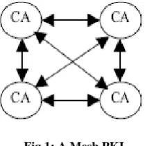
A Mesh PKI is constructed with peer-to-peer CA relationships[6]. It is also called a “web of trust”[7]. In a mesh style PKI, as depicted in Fig1, each subscriber trusts the CA that issued that subscriber's certificate(s). The CAs in this
[image:1.595.393.498.464.570.2]environment have no superior/ subordinate relationship. In a mesh, CAs in the PKI cross certify, that is, each CA issues a certificate to and is issued a certificate by peer CAs in the PKI. The Fig 1 depicts a mesh PKI that is fully cross-certified, however it is possible to construct and deploy a mesh PKI with a mixture of unidirectional and cross-certifications[4]. Compromise of a single CA cannot bring down the entire PKI. Also, Mesh PKIs can easily incorporate a community of users. Since there is a possibility of existence of multiple pathsbetween a relying party‟s trust anchor and the certificate to be verified,certification path construction in a mesh PKI is more complex than in a hierarchical PKI. One more problem is the formation of loops and cycles while constructing the certification path.
Fig 1: A Mesh PKI
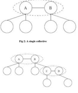
A virtual hierarchy [8] is a logical hierarchy formed in a peer-to-peer network. Like a standard hierarchy, a virtual hierarchy can be modeled as a tree with nodes and directed edges. Leaves can represent bottom-level users. The remaining nodes are virtual CAs. Although each such node is a logical entity in the virtual hierarchy, it represents the collective action of a set of conventional CAs. The term „collective‟ is used for this and is shown in Fig 2.
Balachandra Muniyal
Dept. of Information and Communication Technology,
Manipal Institute of Technology,
Manipal University, Manipal, India.
Prema K.V
Dept. of ComputerScience
andEngineering, ModiInstitute of Technological Sciences,
Jaipur, India,
Sushma Nayak
Dept. of Computer Science and ngineering,Moodlakatte
Fig 2: A single collective
Fig 3: A hierarchy is emerging
In Fig 3, there are two collectives, linked by the member CAs B and C. C is a member of the second collective in collaboration with D in cryptographic computations. From the highest level, the virtual hierarchy (i.e. the logical hierarchy in the peer-to-peer network) is constructed by an algorithm that allows peer CAs to establish a secure connection and negotiate a secret which each of their communities may use as an end-point in their trust chain[8]. Pieces of the trust root (negotiated secret) are then stored among the peers who negotiate it.
2.
A METHOD TO CONSTRUCT
VIRTUAL HIERARCHY IN
PEER-TO-PEER PKI
The proposed algorithm establishes a virtual hierarchy in a peer-to-peer PKI, based on the trustworthiness of the participating neighbor nodes. The upward approach is used to build the hierarchical structure i.e. from the leaves to the root. This approach is easy for the certification path discovery[9] and can be adapted to users with the limited capacities. The main importance is given for multi-rooted approach in case of building a hierarchy i.e. only when such possibility arises. The entire algorithm works in two phases so as to understand the better working of the method.
Gather and order the entities: In this phase, the neighboring entities of the requesting neighbor are collected and arranged them from less trustworthy to the most trustworthy.
Constructing the hierarchy: In this phase, ordered Peer-to-Peer entities are used to establish a
hierarchy may be a single rooted hierarchy or a multi-rooted hierarchy.
2.1
Gather and order the entities with
respect to Trustworthiness
Let us consider the following parameters for the procedure:
PLMAX : Maximum path length allowed
ENTi : Entity i
LEi : Number of certificates from the leaves to entity i. Initially it is set to 0 for all the entities.
LEi,j : This notation is used if the number of certificates from the leaves to entities i and j are same.
INi : Number of entities which ENTi trusts (received certificates).
INi,j: This notation is used if the number of entities that are trusted by ENTi and ENTj are same.
OUTi :Number of entities that trust ENTi (issued certificates)
OUTi,j: This notation is used if the number of entities that trust ENTi and ENTj are same.
ENT0 : Current entity
PN0 : Number of participant neighbors of ENT0
ORDER[PN0+1]: Array that contains ENT0 and its participant neighbors ordered from the less trustworthy.
POS: Position of ENT0 inside the ORDER array.
trustworthy, i.e. by using the IN0 and OUT0 values of ENT0. Based on its processing and storage capacity, ENT0 proposes a max certification path length (PLMAX). log2n is the most appropriate choice for choosing the maximum certificate path length. With this value, the entity ENT0 sends a request message to its neighbors to participate in the protocol. Any of the neighbors can accept or reject to collaborate in establishment of virtual hierarchy, where in acceptance or rejection messages are sent to requesting entity. Once the entity ENT0 receives the responses from all its neighbors, it determines the number of entities that want to be part of the hierarchy that issued certificate to ENT0 i.e. (IN0), and the number of entities that want to participate in the hierarchy that received a certificate from ENT0 i.e. (OUT0). Afterwards, ENT0 and its collaborating neighbors exchange their INi and OUTi values. Later, ENT0 compares OUT0 with the received OUTi values and puts them in order from the lowest to the highest. The entity with the lowest OUTi is the less trustworthy. This is the neighbor that the other participants trust less. If there are two or more entities with the same OUTi, then their INi values are used to order them. After ordering in this manner, if the most trustworthy neighbors have OUTi and INi same, then they both form a trusted anchor(Root nodes), where multi-rooted hierarchy comes into picture. Hence the neighboring entities of the requesting entity(i.e. ENT0) are ordered from the less trustworthy to the most trustworthy.
2.2
Constructing the hierarchy
In the second phase, the construction of the virtual hierarchy is done as follows:
The procedure starts from the less trustworthy entity in the neighborhood. The other entities simply wait for the intervention of their less trustworthy neighbors. A superior CA is chosen by each entity from the participant neighbors that issued it a certificate (trusted neighbors). Thus, when an entity ENT0 acts, it looks for the most trustworthy entity of its trusted neighbors, based on the trustworthiness order established at the first phase of the protocol, and chooses this neighbor as the superior CA. If LE0 is higher than LEi of the superior CA and (LE0 + 1) is less than or equal to (PLMAX - 1), LEi of superior CA takes the value of (LE0 +1). In case that (LE0 +1) is higher than (PLMAX -1), the chosen superior CA is not appropriate and ENT0 must choose the next trusted neighbor as its superior CA provided that this neighbor is more trustworthy than ENT0. ENT0 checks again if LE0 is higher than LEi of the new superior CA. This procedure will continue until ENT0 finds a suitable superior CA. Nevertheless, it can be possible that none of the trusted neighbors that are more trustworthy than ENT0 can be used as its superior CA. When ENT0 concludes this procedure, it sends an association message to its neighbors.
3.
A PRACTICAL EXAMPLE
Fig 4 shows a peer-to-peer PKI with eight nodes that establishes trust relationship among them. Each node receives or sends a signed message among each other which is represented by a directed arrow.
3.1
Ordering the entities with respect to
trustworthiness
If node 1 wants to be a part of hierarchy it sends request message to its neighbors (node 2, node 3, node 5 and node 8), and also it proposes a maximum path length of PLMAX = 3. If node 2 wants to collaborate with node 1 then, it sends an acceptance message to node 1 and a request message to its other neighbors (nodes 1 and node 4), with a value of PLMAX.
Let us consider the ideal condition that all nodes want to be a part of the hierarchy. Hence, node 3 receives request message from node 1 and node 4, so it sends acceptance message to node 1 and node 4 and then sends a request message to its other neighbors (node 2 and node 4), and then node 4 sends request to its neighbor(nodes 3,5,7 and 8) and then at the same time receives request message from (nodes 2,3 and 5) while node 5 has received request message from node 1, node 4, node 6 and node 8, hence returns acceptance message to them, and sends request message to its neighbors (node 4, 6 and 8). Node 6 receives request message from node 1, node 4 , node 5 and node 7 hence returns it with an acceptance message and then sends request message to node 1, node 5 and node 7. The Node 7 receives request message from node 4, node 6 and node 8 and then sends acceptance message to them and then sends request message to node 1, node 5 and node 7. Node 8 receives request message from node 1, node 4, node 5 and node 7, hence it returns an acceptance message to them and afterwards sends them some request message to its other neighbors (node1, node 5 and node 7). Now all the entities will determine their INi and OUTi values and send them in an information message to their neighboring CAs. Fig 4 shows the shared data. Once all nodes obtain the data from all its participant neighbors, put them in order from less trustworthy to the most trustworthy. Hence the nodes know which order they need to act in the second phase of the protocol. For example: from the Fig 4 shown above, node 1 wants to compare its OUT1 parameters with each of its neighboring (participant neighbor's) parameters and orders it, say 1,2,3,5 and 8. In this example OUT1> OUT2 , so OUT1 is more trustworthy than OUT2. In some conditions if OUTi = OUTj then it should check for its INi and INj , based on this, the order of entities are set, i.e. if INi >= INj then node i is considered as most trustworthy entity. If any two nodes are having highest OUTi and OUTj compared to all other participant neighbors(OUTi = OUTj) and both have same INi and INj(INi = INj) , then both are chosen as most trustworthy nodes, i.e. in this example OUT5 = OUT8 = 4 and IN5 = IN8 = 3 and it is having highest OUT(i,j)(OUTi = OUTj) as well as IN(i,j)(INi = INj) then both the entities should be considered as most trustworthy nodes.
Hence, the order of trustworthiness of different nodes is as follows:
node 1 is : 2, 3, 1, 5, 8.
node 2 : 2,3,1,4 ;
node 3: 2,3,1,4;
node 4: 2, 3, 7, 4, 5, 8;
node 5 : 6, 4, 3, 5, 8 ;
node 6 :6, 7, 5;
node 7: 6, 4, 7, 8 ;
node 8 : 4, 1, 7 ,5 ,8.
By comparing all 8 nodes and arranging according to the order of trustworthiness, the order seems to be :
first, later node 2 will act, then node 3 and node 1 will act, then node 7 and node 4 will act finally node 5 and node 8 will act which are the most trustworthy nodes. As Comparing the above said condition with the most trustworthy node and its second most trustworthy node if both OUTi and OUTj and INi and INj are equal then both the nodes are considered as most trustworthy nodes. In this way the multi-rooted hierarchy plays a very vital role where both the CA's with similar weights are given the same priority and placed as root CA.
3.2 Constructing the hierarchy
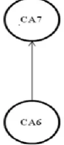
According to the order considered, 6 is the least trustworthy node that forms a leaf node and 5, 8 are the most trustworthy nodes and PLMAX is set to 3 (assuming), PL6 =0. So as to form a hierarchy, node 6 is at the last tier and has to search for its superior node, hence it searches for its trusted neighbors, if it is a root node then it should have a node 5 and node 7 are the neighbors. Whatever node has the highest OUTi it has to be chosen as the superior node. But according to the order of the trustworthiness OUT5 is the most trustworthy node hence the next neighbor is chosen as the superior of node 6 i.e. node 7 is the superior of node 6. LE7 = LE6 + 1 where LE6 = 0 hence LE7 = 1. Hence hierarchy can be shown as Fig 5.
[image:4.595.390.454.393.538.2]Next position has to be considered is node 2, here LE2 = 0 and node 2's neighbors are node 1, node 3 and node 4. OUT1 = 2 , OUT3 = 2 and OUT4 = 3. OUT4> OUT1, OUT3, hence node 1 is considered as the superior CA of node 2. Hence LE4 = LE2 + 1, where LE2 = 0 hence LE4 = 1. This is shown in Fig 6.
Fig 5: Constructing the hierarchy where node 6 chooses node 7 as a superior node
Next Node 3 is to be considered, with LE3 = 0 and the node 3's neighbors are node1, node 2 and node 4. Considering OUT1 = 2, OUT2 = 2 and OUT4 = 3, so node 4 is considered as superior CA of node 3. Thus LE3 = 0, and LE4 = LE3 +1= 1. This is shown in Fig 7.
Fig 7: Constructing the hierarchy where node 3 chooses node 4 as the superior node
[image:5.595.127.201.154.340.2]Next, node 1 is considered, LE1 = 0 and the neighbors are node 2 , node 3, node 5 and node 8. Since node 5 and node 8 have the same OUTi values, they have no other nodes which can be superior to them, so node 5 and node 8 are considered as node 1‟s superior CAs, i.e. LE5,8 = LE1 + 1, where LE1 = 0 hence LE5, 8 = 1. This is shown in Fig 8.
Fig 8: Constructing the hierarchy where node 1 chooses node 5 and node 8 as its superior node
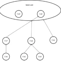
Finally, node 7 and node 4 should act, both have LE7 = 1 and LE4 = 1 and their neighbors are: for node 7: node 4, node 6 and node 8 and for node 4: node 2, node 3, node 7, node 5 and node 8. In case of node 7 , node 8 has the highest OUTi hence considered as Superior CA to node 7, since LE7 = 1, LE8 = LE7 + 1 = 2 which is PLMAX - 1 = 2. Therefore node 8 is confirmed as the Root CA. Similarly, in case of node 4, node 5 and node 8 have the highest OUTi, hence considered as Superior CA to node 4, since LE4 = 1, LE5,8 = LE4 + 1 = 2 which is PLMAX - 1 = 2 . Since node 5 and node 8 are considered as trusted roots, this forms a Multi-rooted hierarchical structure. The final virtual Hierarchy is shown Fig 9.
[image:5.595.168.422.466.724.2]4.
CONCLUSION
In Hierarchical PKI, certificate path is unidirectional, so certificate path development and validation is simple and straight forward. In a mesh or Peer-to-Peer PKI, certificate path verification is a complex task since there exist multiple paths between CAs. In this paper, an efficient method to simplify the Certification Path Discovery in Peer-to-Peer PKI by establishing a Virtual hierarchy is proposed. The resultant hierarchy may be a single rooted or a multi-rooted one. This eliminates the complexity of path verification in Mesh PKI because the path verification in Hierarchical PKI is simple and straightforward.
5. REFERENCES
[1] A. Arsenault and S. Turner, Internet X.509 public key infrastructure: Roadmap, internet draft, PKIX Working Group, IETF, 2002. [Online]. Available: http://ieft.org/internet-drafts/drafts-ieft-pkix-roadmap-08.txt
[2] R. Housley,W. Ford,W. Polk, and D. Solo, Internet X.509 public key infrastructure certificate and CRL profile, IEFT RFC standard 2459, 1999.[Online]. Available: http:www.ieft.org/rfc/rfc2459.txt
[3] Information Technology—Open Systems Interconnection—The Directory:Authentication
Framework, CCITT Rec. X.509/ISO/IEC Standard 9594-8, 1994.
[4] Cristina Satizbal, Juan Hernndez-Serranoa,JordiForna, and JosepPeguerolesa, Building a virtual hierarchy to simplify certification path discovery in mobile ad-hoc networks, Computer Communications, Volume 30, Issue 7, 26 May 2007, Pages 1498-1512.
[5] JordiForne, Jose L. Munoz et.al, Certificate Status Validation in Mobile Ad Hoc Networks, Technical University of Catalonia and University of the Balearic Islands, 2009.
[6] Cristina Satizbal, Rafael Pez, JordiForn, Building a Virtual Hierarchy for Man- aging Trust Relationships in a Hybrid Architecture, Journal of Computers, VOL. 1, NO. 7, October/November 2006.
[7] AshutoshSaxena, Public Key Infrastructure Concepts, Design and Deployment, TMH, 2004.
[8] J. Marchesini and S. Smith, Virtual hierarchies - an architecture for building and maintaining efficient and resilient trust chains, in In NORD-SEC2002 - 7th Nordic Workshop on Secure IT Systems, 2002.