Simulation of Co-channel Interference Ratio (CCIR) for
Directional Antenna in Mobile Computing
Santosh Kumar Rohit pal Mukesh Azad
Department of CSE M.Tech(IT) Student M.Tech(CSE) Student
Graphic Era University Graphic Era University Uttrakhand Technical University
ABSTRACT
Due to the insufficiency of available bandwidth and the continuously growing demand for cellular communication services, there are many cells using same frequency band. All the cell using the same channel are physically located apart by at least reused distance, even though the power level is controlled carefully so that such “co-channels” do not create a problem for each other, there is still some degree of interference due to non-zero signal strength of such cells. This paper concludes Reuse distance (D) with respect to the co-channel interference ratio (CCIR) for mobile station at the various distances from base station (BS).
Keywords
CCIR, Reuse distance, Non-zero signal strength, Mobile Station (MS), Base Station (BS)
1.
INTRODUCTION
Antenna: An antenna is a transducer that converts guided
electro-magnetic energy in a transmission line to radiated
electro-magnetic energy in free space. Electrical energy is fed to the antenna via a transmission line, a conductor which passes electrical energy from one point to another. Antennas may also be viewed as an impedance transformer, coupling between an input or line impedance, and the impedance of free space [7].
Omni-Directional Antenna: An Omni directional antenna is
an antenna which radiates electromagnetic energy uniformly in all directions in one plane, with the radiated power decreasing with elevation angle above or below the plane, dropping to zero on the antenna's axis [2].
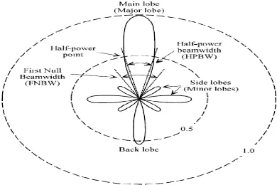
[image:1.595.111.502.408.668.2]Directional Antenna: Directional Antennas concentrate energy into a narrower solid angle than an omni-directional antenna. Directional antennas are used in some base station applications where coverage over a sector by separate antennas is desired. Point to point links also take advantage from directional antennas. A unidirectional pattern such as found on Yagi and quad beams and certain other antennas. The main lobe is the direction of maximum radiation or reception. In addition to the main loop, there are also side lobe and back lobe. [7]
Figure 1 Unidirectional Pattern [2]
On the basis of Figure 1 we can define the various lobes of unidirectional antenna as following-
Main Lobe: The lobe of Directional Antenna that has larger
2.
DISCRIPTION OF FREE SPACE
PROPAGATION MODEL
The free space power received by a receiver antenna which is a distance of d from the transmitter antenna is given by Friis free space equation[9].
𝑃𝑟= 𝑃𝑡𝐺𝑡𝐺𝑟 4𝜋𝑑λ 2
(1.0) Where, Pt is the transmitted power, Gt is the transmitting
antenna gain, Gr is the receiving antenna gain, and d is the
separation distance between antennas and λ is the signal
wavelength [9],[10].
The path loss which represents the signal attenuation as a positive quantity is defined as the difference between the effective transmitted power and the received power and may or may not include the effects of the antenna gains. The path loss for the free space model when the antennas are assumed to have unity gain is provided by the following equation [11],[12].
Pt
Pr= (
4πd λ )2
Pt
Pr = (
4πdf c )
2 (2.0)
Where f is the signal frequency. c is equal to the speed of light (3*108 meters per second)
Free-space path loss in decibels
𝐹𝑆𝑃𝐿 𝑑𝑏 = 10log(𝑃𝑡 𝑃𝑟)
= 10log(4𝜋𝑑𝑓 𝑐 )2 = 20log(4𝜋𝑑𝑓
𝑐 )
= 20 log 4𝜋 + 20 log 𝑑 + 20 log 𝑓 − 20log(3 ∗ 108)
= 21.98 + 20 log 𝑑 + 20 log 𝑓 − 169.54 = −147.56 + 20 log 𝑑 + 20log(𝑓) Therefore,
𝐹𝑆𝑃𝐿 𝑑𝑏 = −147.56 + 20 log 𝑑 + 20 log 𝑓 (3.0)
where, d is in meters, f is in Hz.
3.
CO-CHANNEL INTERFERENCE
RATIO(CCIR)
[image:2.595.177.384.341.532.2]The co-channel interference ratio (CCIR) can be calculated using directional antenna, in worst case for three sector directional antenna is shown Figure.2
Figure 2 The worst case forward channel interference in three sectors (directional antenna) [4]
Where D is Reuse distance, R is Radius of each cell,
D = 9 2∗ R
2
+ 3 2 ∗ R
2
D = 21 R (4.0) D ≅ 4.58R
And
CI= q−γ +(q+0.7)1 −γ (4.2)
Where C is carrier, I is interference and γ is the propagation path loss slope
4.
ANALYSIS OF CCIRON THE BASIS
FREE
SPACE
PROPOGATION
Figure 3 CCIR for different values of path loss constant (λ)
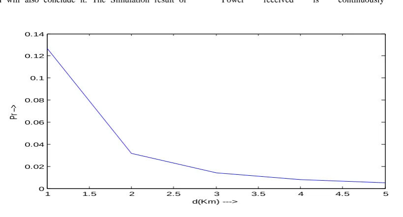
Simulation of CCIR for different values of path loss constant (λ) from 2 to 5, It is observe that 4 is optimum value as simulation will also conclude it. The Simulation result of
[image:3.595.90.500.324.545.2]equation (2.0) of Free Space Propagation Model concludes Figure 4 That shows that as Mobile Station move from Source Power received is continuously decreasing.
Figure 4 Receiver Power (Pr) with respect to distance
5.
PROPOSED
SCENARIO
FOR
REUSED DISTANCE
Figure 5 shows the simulated radiation patterns of the micro strip patch antenna on the finite ground with slots and without
slots. It shows that the backward radiation from the micro strip patch antenna with
Slotted ground choke can be dramatically reduced about 45dB more than without slots.[8]
2 2.5 3 3.5 4 4.5 5
0 5 10
15x 10
4
propagation path loss slpoe
CC
IR
1 1.5 2 2.5 3 3.5 4 4.5 5
0 0.02 0.04 0.06 0.08 0.1 0.12 0.14
d(Km) --->
Pr
Figure 5 The simulated radiation patterns of micro strip patch antenna on the finite ground plane with/without slots [8]
From Figure 5 it can be derived that main lobe and back lobe are prime factor affecting the CCIR. From CCIR analysis and simulation of radiation patterns of micro strip patch antenna
[image:4.595.63.534.320.480.2]Reuse distance (D) can be computed from equation 4.0 for Main Lobe. For back lobe it will constant due to its dependency upon internal structure and design of antenna.
Figure 6 Reused distance for directional antenna of beam-width 65 degree
Figure 6 shows radiation pattern of Directional Antenna both main lobe as well as back lobe. If Mobile Station on Main lobe i.e. is between angle with respect to north 322.5° and
32.5°, then Reuse distance D=√21R. In case of side lobe i.e.
angle 32.5° to 142.5°and 212.5° to 322.5°it is zero. But in
case of back lobe just 180° from main lobe i.e. angle 142.5°to 212.5° it is constant c. On observation maximum value of c is
[image:4.595.70.527.568.695.2]300 m.
Table 1. Frequency reuse distance (D)
S. No. Direction(θ) Reused distance(D) Radiation pattern
1. 322.5<θ<32.5 √21R Main lobe
Future work will be, with more practical real life data set which can be design for a Planning tool that will be capable of automatic frequency planning for getting minimum interference of the co-channel and could be go further for adjacent channel.
7.
REFERENCES
[1] Santosh Kumar, Sandip Vijay, S. C. Sharma, Shahnawaz Husain ,Simulation of Co-channel Interference Ratio (CCIR) for Omni-Directional Antenna in Mobile Computing, 2009 IEEE International Advance Computing Conference (IACC 2009)Patiala, India, 6– 7March 2009
[2] Joseph J. Carr ,Joe Carr's Radio Tech-Notes Directional or Omnidirectional Antenna? , Universal Radio Research 6830 Americana Parkway
[3] Luís M. Correia,Mobile Broadband Multimedia Networks: Techniques, Models and Tools for 4G
[4] Dharma Prakash Agrawal and Qing- An Zeng,” Introduction to Wireless and Mobile System” University of Cincinnati.
[5] J. Proakis, Digital Communications. McGraw-Hill, 4ed., 2000 3GPP, Digital Cellular Telecommunications System (Phase 2+). Technical specification TS 05.01-05,http://www.3gpp.org
[6] J. Proakis, Digital Communications. McGraw-Hill, 4ed., 2000.
[7] H. Schantz, “A Brief History of UWB Antennas”IEEE UWBST 2003.
[8] Won-Gyu Lim et All, New Method for Back Lobe Suppression of Microstrip Patch Antenna for GPS, Proceedings of the 40th European Microwave Conference
[9] R. G. Kouyoumjian and P. H. Pathak, “A uniform geometrical theory of diffraction for an edge in a perfectly conducting surface,” Proceedings of the IEEE, vol. 62, no. 11, pp. 1448–1461, 1974
[10] J. B. Andersen, “UTD multiple-edge transition zone diffraction,” IEEE Transactions on Antennas and Propagation, vol. 45, pp. 1093–1097,1997.
[11] S. V. Savov and M. H. A. J. Herben, “Modal transmission-line modeling of propagation of plane radiowaves through multilayer periodic
building structures,” IEEE Transactions on antennas and propagation, vol. 51, no. 9, pp. 2244–2251, 2003. [12] Pratt, T. & Bostian, C. W. 1996, Satellite
![Figure 2 The worst case forward channel interference in three sectors (directional antenna) [4]](https://thumb-us.123doks.com/thumbv2/123dok_us/8115940.792503/2.595.177.384.341.532/figure-worst-forward-channel-interference-sectors-directional-antenna.webp)
![Figure 5 The simulated radiation patterns of micro strip patch antenna on the finite ground plane with/without slots [8] Reuse distance (D) can be computed from equation 4.0 for Main Lobe](https://thumb-us.123doks.com/thumbv2/123dok_us/8115940.792503/4.595.113.480.76.254/figure-simulated-radiation-patterns-antenna-distance-computed-equation.webp)
