Enhanced Handover Mechanism in Long Term
Evolution (LTE) Networks
Mohsin Khan
1, Majid Ashraf
1, Haseeb Zafar
1and Tufail Ahmad
21University of Engineering & Technology, Peshawar, Pakistan 2
CECOS University of Information Technology and Emerging Sciences, Peshawar, Pakistan [email protected], [majid, haseeb] @uetpeshawar.edu.pk, [email protected]
Abstract: Femtocell is a low power base station, wireless access
point designed especially for homes and small organizations. It is promising technology for operators to improve their capacity and for users to give indoor coverage. As mobile users are increasing day by day so the legacy system is unable to provide such a high data rates to all these users. In this case femtocells play a key role to offload the data traffic from macro base station. The implementation of femtocell has posed so many challenges like interference, localization, access control and mobility management. The aim of this paper is to present an enhanced algorithm for handover in Hand-In scenario. In already existing algorithms handover is decided on the basis of a single parameter but here we have simulated an algorithm that considers multiple parameters instead of a single parameter for handover. Through this algorithm, the most suitable femtocell will be selected for handover, hence number of handovers will be decreased. Simulation results show that the system performance has been improved.
Keywords: Femtocell, Handover, Interference, Macro-cell, Hand-In,
Mobility Management.
1.
Introduction
Nowadays, one can observe that the capacity demand for mobile wireless communication has increased up to a larger extent and the mobile operators are trying to bring innovative and low cost solution to meet the requirements of users. According to a survey by International Telecommunication Union, data capacity is used 5% more by the smartphone users comparatively to standard phone users. The annual penetration of smartphones is 30% while demand for capacity is 70-200% per year. Current legacy network cannot compete with this data explosion as these are already saturated and having capacity crises. Due to limited availability of resources the existing technology cannot utilize the advance applications in an efficient way and there are issues that need to be solved.
This prominent increase in the data traffic has got the attention of researchers to this area to bring about new ideas and such network topologies that efficiently fulfill the demands of the users [1]. A study on wireless usage indicate that 2/3 of the voice and 90% of data traffic is indoor so researchers suggested to offload the data traffic from macro-cells which will be a great relief for operators and as well as subscribers.
Too much attention was given to the transmitting signals in order to find their better formats and also to the improvement of transmitter and receiver technology. Other approach for solving the problem of capacity and coverage is to bring the transmitter and receiver into close vicinity of each other. Operators lost their interest in this approach as this was not
economically viable due to the deployment of Base Stations (BS). Hence, network operators opted for small cells known as femtocells as a solution for the improvement of network coverage that specifically address the indoor mobile users. For the service providers, this integration of femtocells in macro-cell not only offloads the traffic but also brings reduction in the investment capital, operational costs and maintenance cost [2]. Moreover, it also makes the cellular network reliable. Advantage to the indoor user is high data rate while they are surfing internet in their homes and offices in an urban area.
These small cell base stations are also termed as Femto Access Points (FAPs), and are short range and low power i.e. 10-30m and 10-100mW respectively [3]. It has got the benefit of Plug-and-Play device so that users can easily operate these devices. Femtocells work in the licensed spectrum owned by the operator and are connected to the core network through DSL, cable or optical fiber. It is installation is quite different from macro-cells, as these are Plug and Play devices so a user can easily install and maintain it in an unplanned manner. This uncoordinated nature of femtocells has created problem of Radio Resource Management and handover. For the integration of femtocells in the LTE-A existing network it is necessary that there should be efficient procedures for the handovers [4].
The integration on femtocells into macro-cell results in a two-tier network and the handovers algorithms that are used in rationally in macro cell cannot satisfy the mobility of user in such a two-tier network. In the literature, there are various handover schemes that are based on different parameters as decision parameters but they are not sufficient for tow-tier network. We have presented an algorithm that considers more than one parameter for the handover decision.
2.
Background
technologies. The main features of LTE-A, are Carrier Aggregation (CA), enhanced Multi Input Multi Output e-MIMO, Coordinated Multipoint (CoMP) Transmission and Reception, support for Heterogeneous Networks (Het-Nets) and Relaying.
LTE-A has improved throughput due to CA, which is the fragmentation of the bandwidth into small components for the transmission between mobile and base station [6]. There must be five fragments but the whole transmission must not exceed 100 MHz [7]. Increased data rate, system level performance and improved coverage is obtained through e-MIMO in which antennas are extended up to 8×8 for DL and 4×4 for UL [8]. In order to improve the cell edge through put an advanced form of MIMO was introduced in LTE-A, called CoMP [9]. In earlier wireless communication technologies single carrier modulation techniques were used which created the problem of multi-path fading and Inter Symbol Interference (ISI) but LTE-A eliminated all these issues by multiple modulation carrier i.e. OFDMA for Dl while SC-FDMA for UL. Besides all these technologies in LTE-A, there is support for heterogeneous networks for the improvement of coverage and capacity.
The aim of LTE-Advanced is not only to improve the throughput for external users but also has given preference to the indoor users i.e. to improve the coverage and capacity. This whole idea revolves around the deployment of heterogeneous (Het-Nets) networks. With such deployment, indoor users can smoothly use the advance application of LTE-Advanced and thus the revenue of operators can be increased. The macro-cell serve the large area with low rate services while on the other hand these small base stations serve small coverage area with high speed services. Het-Net is a mixture of few low power nodes like macro-, Femto-, pico-, and Remote Radio Heads (RRH). These are categorized on the basis of Transmission Power, Access, Deployment Methods and Backhaul Connectivity [10]. For the improvement of spectral efficiency, throughput, coverage and capacity different techniques were used like enhanced antennas and different small base stations like pico-cells and even Nano-cells but all these technologies have their limitations. For instance, Relays, cannot improve the indoor coverage and the cost of micro and Nano-cells is quite high for operators to afford.
So, for the improvement of system capacity and performance 3GPP for the first time in release 8 introduced the usage of home base stations in the existing networks and in the upcoming generations [11]. Femtocells are called Home NodeB (HNB) in LTE while in LTE-Advanced these are termed as Home enhanced NodeB (HeNB).
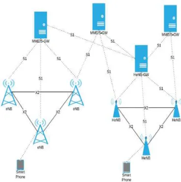
The architecture of 3GPP LTE-Advanced has three main components: UE, eNodeB and the Evolved Packet Core (EPC) network so femtocells were included in the existing network to function and interact with the network as other components do. The eNodeBs are connected to each other and as well as to the Mobility Management Entity (MME), for inter-eNodeB handover there is X2 interface between eNodeBs. For LTE access network MME plays a key role of control node and whose function is to process the signals between UE and Core Network while S-GW controls the data
traffic.
The femtocell network is composed of HeNB and HeNB Gateway. This new element is present between HeNB and the Core Network. At this position, it acts as a sort of dual role, like for Core Network it’s a sort of “virtual” macro eNB while for HeNB act as “virtual” Core Network. Too many HeNBs are connected to HeNB-GW through S1 interface. These S1 and X1 are nothing but just logical interfaces for the transfer of signals through logical layer. All these components are given in Figure 1.
Figure 1. Integration of Femtocell in LTE network i.e. Two tier network.
In femtocells, the access of users can be control in three ways [12]. First one is Closed Access mode in which users are registered in a group called Closed Subscriber Group (CSG), so that only registered users can access the femtocell. Second one is Open Access mode in which any user can access the femtocell and can avail its services but it’s not secure. Hybrid mode is a mixture of open and closed type in which preference is given to those users which are registered. The deployment of femtocells in the existing network has improved the system capacity and also the coverage but on the other hand this deployment has posed so many challenges for the operators. The main technical challenges are Interference, Mobility and Handover, Backhaul, Restricted access, Synchronization and localization.
3.
Handover Scenarios
The mobile user moves randomly so according to its movement there are three types of handover scenarios. Hand-In is a type of scenario when a user moves from a macro-cell to a femtocell [13]. From the handover perspective, it is a complex scenario as there are so many femtocells so it is hard for the mobile user to decide which one is more suitable for handover. Hand-Out is a scenario when a user leaves femtocell and enters in to macro-cell area. This one is rather simple as there is not much scanning for the cells as the target cell is just one macro-cell. The last one is Inter-Femtocell handover which is between femtocells to femtocell. It is also very challenging as there will be so many target femtocells. For such scenario, there is need of efficient handover techniques.
The handover enables the movement of user from one cell to another cell while using the services uninterrupted. So is the case with femtocell, whenever a user moves from or into femtocell it will need a handover to use the services seamlessly. We have discussed different scenarios that whenever a user moves from a macro-cell to a femtocell or from one femtocell to another femtocell it will need a handover and such handover scenarios are complex. As the femtocells are densely deployed and the coverage area is small so whenever a user moves it undergoes frequent and unnecessary handovers which effects the QoS a lot. So, we need such a handover algorithm that decrease the number of handovers and improves the QoS and also the coverage. Handover Management is one of the key driver for the seamless service to the user in the deployment of femtocell in already exiting LTE-Advanced network [12]. A typical handover technique is composed of few steps that are listed below.
1. Measurement Report. 2. Handover Decision. 3. Handover Execution.
In literature, there are already different handover algorithms which are going to discuss in the next section.
3.1 Received Signal Strength Based Handover
Algorithm
This class of handover algorithm is based on Received Signal Strength [14]. In order to minimize the probability of HO along with ping pong effect this sort of algorithm consider a threshold called HO Hysteresis Margin for the comparison of signal strength between serving and target cell.
This algorithm considered the asymmetrical transmission powers of macro-cell and femtocell but did not consider other parameters like BW, UE speed and access technique in this single Macro-Femto model.
3.2 Received Signal Strength and Path Loss
Model HO Algorithm
In this technique, they have considered two parameters for Hand-in scenario i.e. RSS and Path loss. They have selected a minimum threshold and handover would be possible if RSRP is greater than threshold plus HHM. Third parameter is path loss [15].
This algorithm is enough good as this has taken path loss between UE and FAP as a decision parameter but this there is often variation in path loss which has impact on the HO failure, one thing more is that the scenario consists of single macro and single femtocell which is not realistic approach.
3.3 Neighbor Cell List Optimization Algorithm
The focus is on the NCL problem in quite dense network. They implemented this algorithm on inter-Femtocell scenario. In this algorithm, they have decreased the number of femtocells in NCL based on the user movement and location information of neighbor FAP. They have minimized NCL but have not set any parameter for suitable FAP for handover [16].
4.
Proposed Algorithm
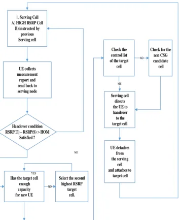
This algorithm has improved the performance of femtocell in terms of decreased number of handover and improved QoS. The flow chart of proposed algo is given in Figure 2. The scenario is composed of a single macro-cell and multiple femtocells. As we have discussed that the three kinds of scenario regarding handover and we have opted for Hand-In scenario, in which a user is going to enter from a macro-cell to a femtocell area. The problem arises in this scenario when a user enters from a macro-cell to a femtocell area like residential building or an organization so for a user there are so many femtocells. As femtocell, has limited coverage and are deployed with in close vicinity of each other. In such a scenario, the UE suffers from frequent and unnecessary handovers that effects the QoS. UE is unable to select a best suitable FAP for handover.
A multi-step handover algorithm is presented in this paper that will decrease the number of unnecessary handovers and select the best suitable FAP for the incoming UE. Here the cell to which UE is already connected is termed as Serving Cell and the other cell to which handover is expected is called as Target Cell. Our algorithm consists of three phases of filtering which will decrease the number of FAP in Neighbor Cell List (NCL) and will filter out the best FAP for handover.
The first phase of filtration is that UE will measure the power of the femtocells. As we know that the UE is constantly sending the measurement report to the
serving
cell that contains signal power, SINR and so on. UE will compare the power of femtocells with Handover Margin (HOM). HOM is a variable that specify a threshold for the comparison between the Reference Signal Received Power of macro cell and target femtocell. Another variable is Time to Trigger (TTT) that is duration for which the handover condition is checked.RSRP(T) -RSRP(S) >HOM (I)
Here RSRP(T) and RSRP(S) are the signal powers of Serving
Cell and target Cell received by the UE.
1. Serving Cell
A) HIGH RSRP Cell B) instructed by
previous Serving cell
UE collects measurement
report and send back to serving node
Handover condition RSRP(T) –RSRP(S) > HOM
Satisfied ?
NO
Has the target cell enough capacity for new UE
Select the second highest RSRP target cell. NO Check the control list of the target
cell
YES
Serving cell directs the UE to handover to the target cell
YES
Check for the non CSG candidate cell NO UE detaches from the serving cell and attaches to
target cell
Figure 2. Flow chart of Proposed Algorithm
Now there may be one or more FAP whose RSRP is greater than that of serving cell so its again complicated for the UE to which will it handover. If UE handover to a cell but it does not have enough bandwidth to support an extra UE so the handover will be failed and UE will again start searching for another FAP. This problem will increase the signal overhead, more usage of battery and also disturbs the QoS.
To mitigate this issue, we have presented another phase of filtration that will further filter out the femtocells which cannot support a new UE and hence unnecessary handover number will be decreased. After measuring the signal power of the femtocells, the available bandwidth of these FAP is measured. So, if the RSRP of a target cell is greater than the RSRP of serving cell and it has the capacity to support a new UE then UE will be handover to that FAP. In this way, a suitable FAP will be selected for seamless switching from serving cell to target cell.
The last step is to determine whether the UE is registered in the Closed Subscriber Group or not. If it is registered in the CSG then handover will be triggered otherwise not so this FAP will also be discarded and a non-CSG cell be searched for handover from the NCL. If all these steps are not satisfied in the specified TTT then the handover will be reset and UE will again start searching and will be connected to the Serving cell.
By following the three steps of filtration discussed in this algorithm a number of FAP are excluded from the NCL to which handover was expected and other advantage is that a suitable FAP will be selected for handover. In this way, the number of unnecessary handovers will be decreased and will provide better services for the user during handover from macro-cell to a femtocell.
After the handover triggering criteria is fulfilled, handover execution is performed by sending the HO request to the
Mobility Management Entity (MME). After acknowledgment from MME Ho command is send to the UE and it is detached from the serving cell to the target cell and thus handover is completed.
5.
Modeling of Femtocell in LTE-SIM
In order to simulate the proposed algorithm, we used LTE-Sim as a simulator. LTE-LTE-Sim is an event driven environment, written in C++ language using object-oriented platform [15]. This simulator has four main modules which are: 1) the Simulator, 2) the Network Manager, 3) the Flows Manager and 4) the Frame Manager. In this simulator, there are different classes through which each node of LTE network can be implemented. These classes are eNB class, UE class, and much more. There is another class in this simulator called protocolStac class whose function is to provide different LTE functionalities like e-UTRAN models and EPC, mobility, handover techniques and frequency reuse. The whole LTE protocol stack consists of three network nodes which are UE, eNB and MME.
Moreover, LTE-Sim also supports well known scheduling algorithms like Proportional Fair (PF), MLWDF, ExPF, Log rules and AMC schemes [17]. CQI feedback is also supported by this simulator and this is done by the conversion of channel quality estimation report from mobile to CQI feedbacks and is reported to eNB. Four traffic generators have been developed in this simulator i.e. trace-based, on-off, infinite buffer, and constant bit rate. In LTE-Sim, Channel module covers the models for packet transmission and propagation loss. This is done by four different phenomena the path loss, the penetration loss, the shadowing and fast fading. When a macro user is inside a building in such a case this simulator considers additional factor of attenuation due to the presence of external walls and also considers WinnerII channel model for residential HeNB users. We have mentioned so many features of LTE-Sim which makes it flexible to use a complete system to simulate a femtocell scenario. Following are the steps for creating a femtocell scenario in LTE-Sim:
• Creation of Femtocell Scenario
• Creation of Femtocell User
5.1 Creation of Femtocell Scenario
This step means that we will have to construct FAPs inside buildings. Unique IDs are used for the identification of FAPs and eNBs while Cartesian coordinate system can be used to define their positions [17]. All the information about UE like CQI feedbacks, uplink channel quality and uplink scheduling requests are managed by ID and position tracking. In LTE-Sim there is a header file “SingleCellWithFemto.h” which is used for creating scenario by giving information about the number of buildings, location of building with FAP, type of building and location of FUE etc.
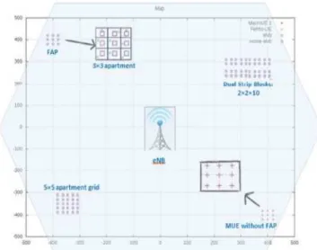
10 apartments. The later one is a grid of 5 × 5 which has total of 25 apartments. According to the traffic environment this grid can also be modified. Different building types in
LTE-SIM are shown in Figure 3.
Figure 3. Different building types in LTE-SIM
In this paper, we have considered a 3 × 3 grid and 5 × 5 as well. These are shown in shown in Fig. 3. In our scenario, the length and width of an apartment has been kept 10 meters which makes the area to be 100m2. In such a building type, each apartment with a single femtocell is considered. This will give us a total of 9 femtocells for a 3 × 3 grid and 25 femtocells per apartment for 5 × 5 grid. All these settings for grid of apartments inside a building can be done by the configuration of grid settings in the header file “SingleCellWithfemto.h”. NetworkManager.cpp forms the building walls while the building is built by the function. NetworkManager:CreateBuildingForFemtocells() which gets the building ID form the main header file.
For the location of femtocell there is another header file i.e. IndoorScenario.h through which a femtocell can be placed at the center of an apartment. In that scenario, there is an array of x_offset and y_offset which denotes the coordinates of each and every FAP in an apartment.
5.2 Creation of Femtocell User(FUE)
In LTE-Sim there are also shell scripts rather than header files and these scripts are used for setting up the number of FUE. At the beginning of the simulation these scripts generate loops for the creation of coordinates for each FUE. In this paper, the coordinates of the UE are the same as the FAP.
6.
Simulation Results
In this section, simulation results of our proposed algorithms are discussed which is related to the decrease in number of unnecessary handovers and improvement in the throughput of UE. The simulation results showed the improved performance of the proposed algorithm with the deployment of 3 × 3 & 5 × 5 femtocells grid using different scheduling algorithms i.e. PF and MLWDF. The simulation parameters are given in the Table 1.
In this paper a scenario is investigated in which a macro UE
enters in to a building having multiple FAP. An algorithm is presented so that a UE can select the best possible FAP for handover to decrease the number of unnecessary handovers and also improve the throughput of the user. In macro-cell an eNB is considered that operates in 20MHz bandwidth with an omni-directional antenna and located at (0, 0) position.
Table 1. Parameters & their values used in Proposed
Algorithm.
A. Parameter B. Value
C. Bandwidth D. 20MHz
E. Frame Structure F. FDD
G. eNB Power Transmission H. 43dBm
I. FAP Power Transmission J. 20dBm
K. CQI L. Full bandwidth and
Periodic Reporting Scheme
M. Apartment size N. 100m2
O. Building P. 1
Q. Users R. 5 per Femtocell
S. Traffic T. VoIP
Main object of the study is:
• A two-tier network having Macro-cell and femtocell is considered where conventional power based handover algorithm is considered as reference.
• The same scenario is considered but with multi-filtering algorithm is used for handover from macro-cell to femtomacro-cell.
The number of users was fixed and mobile, each user is getting real-time downlink (VOIP) flow from a source having infinite buffer.
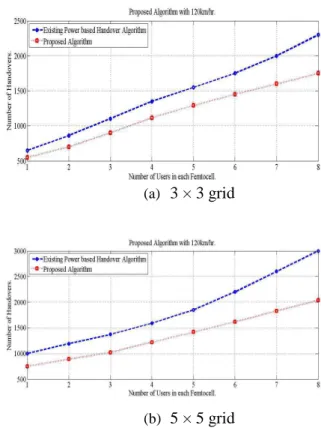
Figure 4 is the comparison of conventional power based handover algorithm and our proposed algorithm where the mobility of user is kept as pedestrian. This shows that the number of unnecessary handovers decreased up to a greater extent with the proposed algorithm.
The same proposed algorithm is applied on the scenario while the users are moving with the speeds of 5, 15, 30 and 120km/hr.
From Figure 5, Figure 6 and Figure 7, we can conclude that as the speed of user has increased above 15km/hr. the number of handovers increases because the user does not remain connected with the femtocell and switches between femtocells. One other point is that for the same speed of the user the number of handover has increased for 5 × 5 comparatively to 3 × 3, it is due to the reason that the number of femtocell has increased.
(a)
3 × 3 grid
(b)
5 × 5 grid
Figure 4. Number of handovers with proposed algorithm while user is pedestrian for both type of grids.
(a)
3 × 3 grid
(b)
5 × 5 grid
Figure 5. Number of handovers with proposed algorithm while user is moving with 15km/hr. for both type of grids.
(a)
3 × 3 grid
(b)
5 × 5 grid
Figure 6. Number of handovers with proposed algorithm while user is moving with 30km/hr. for both type of grids.
(a)
3 × 3 grid
(b)
5 × 5 grid
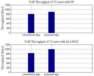
From the resulting graph as shown in Figure 8 and Figure 9, it is quite evident that the average throughput of the network has improved with the proposed handover algorithm. Throughput with M-LWDF scheduler is higher than PF because this channel aware scheduler also considers QoS requirements during scheduling while PF is unable to consider QoS requirements thus making it unsuitable for real-time applications.
Figure 8. Comparison of throughput between power based and proposed algorithm for 3 × 3 grid.
Figure 9. Comparison of throughput between power based and proposed algorithm for 5 × 5 grid.
7.
Conclusion
In this paper, the focused is on the mobility management of femtocells in two-tier network. The main aim of the integration of femtocell into LTE-A architecture is to offload
the data traffic from macro-cell to femtocell because the number of mobile user is increasing day by day which makes the network congested and lower the system performance. The integration of femtocells in Macro-cells also introduced the problem of mobility management and especially the handover between different networks. As frequent handovers occur due to the movement of users from Macro-cells to femtocells which effects the system performance and QoS. In this regard, the algorithm is proposed that considers Hand-In handover scenario in which a user moves from a macro-cell in to a femtocells cluster. In such a scenario handover to a femtocell depends upon various parameters. We have taken RSRP, capacity of the femtocell and CSG as the criteria for handover. The simulation results showed that the proposed algorithm has far better performance than already existing algorithms.
References
[1] Jeffrey G. Andrews, Holger Claussen, Mischa Dohler, Sundeep Rangan, Mark C. Reed, “Femtocells: Past, Present, and Future.” IEEE Journal on Selected Areas in communications, Vol-30, No-3, 2012.
[2] Mostafa Zaman Chowdhury, Yeong Min Jang, ZJ Haas, “Network evolution and QoS provisioning for integrated femtocell macrocell networks,” International Journal of Wireless & Mobile Networks (IJWMN) Vol.2, No.3, 2010. [3] Zahir, K. Arshad, A. Nakata, K. Moessner, “Interference Management in Femtocells” IEEE Communications Surveys & Tutorials, Vol. 15, pp. 293-311, 2013.
[4] Chowdhury, M.Z. & Jang, Y.M. J, “Handover management in high dense femtocellular networks”, Journal in wireless communications and Networking. 2013.
[5] Technical Report, “3rd Generation Partnership Project; Technical Specification Group Radio Access Network; Evolved Universal Terrestrial Radio Access (E-UTRA); Further advancements for EUTRA physical layer aspects” (Release 9) 3GPP TR 36.814 V9.0.0 2010.
[6] Technical Report, “3rd Generation Partnership Project; Technical Specification Group Radio Access Network; Feasibility study for Further Advancements for E-UTRA (LTE-Advanced)” (Release 11). 3GPP TR 36.912 V11.0.0 2012.
[7] Ekta Gujral and Jitendra Singh Jadon, “LTE Evolution towards Carrier Aggregation (LTE-advanced),” Journal of Telecommunications System & Management, Vol 5, Issue 1, 2016.
[8] R. Bendlin, V. Chandrasekhar, C. Runhua, A. Ekpenyong, and E. Onggosanusi, "From homogeneous to heterogeneous networks: A 3GPP Long Term Evolution rel. 8/9 case study,” 45th Annual Conference, Information, Science and System. (CISS), Baltimore, MD, pp. 1-5, 2011.
[9] Md. Shipon Ali, “On the Evolution of Coordinated Multi-Point (CoMP) Transmission in LTE-Advanced” International Journal of Future Generation Communication and Networking. Vol.7, No.4, pp.91-102, 2014.
[10] Stephan Parkvall, Anders Furuskar, Erik Dahlman, “Evolution of LTE toward IMT-Advanced,” IEEE Communications Magazine, Vol. 49 Issue 2, 2011.
[11] Jeanette Wannstrom, “LTE-Advanced, for 3GPP,” 2012. [12] Ian F. Akyildiz, David M. Gutierrez-Estevez, Elias Chavarria Reyes, “The Evolution to 4G cellular systems: LTE-Advanced,” Elsevier Journal, Physical Communication, Vol. 3, Issue 4, pp.217-244, 2010.
Handover Strategy in Femtocell Network” Journal of Communications Vol. 8, No. 11, 2013.
[14] J.-H Moon, D.-H Cho, “Efficient handoff algorithm for inbound mobility in hierarchical macro/femto- cell networks,” IEEE Communication. Mag. Letters, vol.13, no.10, pp.755-757, 2009.
[15] Peng Xu, Xuming Fang, Rong He, Zheng Xiang “An efficient handoff algorithm based on received signal strength and wireless transmission loss in hierarchical cell networks” Telecommunication Systems. J., Elsevier, Vol.52, Issue 1, pp. 317-325. 2013.
[16] Faisal A. Al-Shahin, “Femtocell-to-Femtocell Handoff Management in Dense Femtocellular Networks” International Journal of Computer and Communication Engineering, Vol. 4, Issue No. 5,2015.
[17] G piro, L Grieco, G Boggia, F Capozzi, P Camarda “Simulating LTE cellular systems: an open-source framework” IEEE Transactions on Vehicular Technology, vol.60, Issue no. 2, pp.498-513, 2011.