Design Method and Feasibility Study
of Fully Actively Controlled Frames
A. Joghataie
and M.M. Asbmarz
1In this paper, results of a preliminary study on the feasibility of using an Active Tendon Control (ATC) mechanism for frame structures subject to earthquakes is presented. So far, the ATC mechanism has mainly been considered as a means for installation on structures to mitigate their response under severe loading. In this study, it is desired to evaluate the possibility of using the ATC mechanism to serve as the main means for the stability of frames against earthquakes. Hence, a methodology is presented for the integrated design of frames with ATC mechanisms, which is tested numerically. A number of ve-, ten-, fteen- and twenty-story steel frames are used for this purpose. To this end, rst, each of the frames is designed in accordance with the Uniform Building Code of Practice (UBC). Then, the same structure is re-designed for its dead load only, but equipped with a number of ATC mechanisms that help the structure withstand earthquake loading, so that its overall behavior is similar to the UBC frame. This results in a reduction of the cross-sectional dimensions and weight of the columns at the expense of providing the required hydraulic actuator(s), the sensory system, the controller chip(s) and the prestressed tendons. The ATC frame so designed is, then, considered to be equivalent or comparable to the UBC frame. Furthermore, the behavior of the ATC and UBC designs are compared.
INTRODUCTION
The attention of researchers in the area of active control of structures, has been attracted mainly to-wards proposing new structural control algorithms and mechanisms, including their assessment through numerical simulation. The interested reader may refer to Leipholz 1] and Soong 2] for more details about classical and optimal control and, also, Joghataie and Ghaboussi 3], Ribakov et al. 4], Joghataie and Vahidi 5], Bani-Hani and Ghaboussi 6] and the pro-ceedings of the Third World Conference on Structural Control (3WCSC 2002) 7], for a few examples of the more recently proposed active control methods and mechanisms. Some researchers have tried to provide a more realistic understanding of the idea of active struc-tural control through experimenting with reduced scale models of frame structures 2,8-10]. Some attempts have been made by a number of companies in Japan to install some sorts of hybrid and active mass dampers on the top of several buildings there, as reported
*. Corresponding Author, Department of Civil Engineering, Sharif University of Technology, Tehran, I.R. Iran.
1. Department of Civil Engineering, Sharif University of Technology, Tehran, I.R. Iran.
in Spencer and Sain 11]. However, little attention has been paid to the methodology of engineering design, technology and the required hardware for the implementation of active control mechanisms to real structural systems and its related economics. Although it may seem too early to comment on these issues, as we are still far from routinely constructing actively con-trolled structures, the provision of information in this regard is essential in bringing the idea closer to reality by opening new discussions and viewpoints about how to try to make these ideas more practical. This study is hoped to serve as another step towards this goal. To this end, through numerical simulations, a number of frames of dierent heights were designed according to the Uniform Building Code (UBC, 1997) 12]. Then, the same frames were designed for their dead loads only. However, they were equipped with one or several active tendon control (ATC) mechanisms to withstand earthquake. The methodology for designing ATC frames is detailed in the paper.
The instantaneous optimal control algorithm pro-posed by Yang et al. 13], was used for the derivation of control rules. Reduction in the weight of the material used, on the one hand, versus the required actuator(s) capacity(s) + tendon length, on the other hand, is reported as the criteria for assessing the
benet and cost of the active control strategy used here.
In the following sections, rstly, a brief about the instantaneous optimal control algorithm is presented. Secondly, the methodology of integrated design of ATC frames is provided. Results of the UBC and ATC designs of a number of ve-, ten-, fteen- and twenty{story frame structures are reported in detail and, nally, some preliminary conclusions are drawn on the economics of the active tendon control strategy, compared to the conventional code-based design of the frames.
INSTANTANEOUS OPTIMAL CONTROL
METHOD
Amongst the many proposed control methods, the closed-loop instantaneous optimal control is one of the simplest, whilst one of the most suitable, for studies such as this. A thorough explanation of the method can be obtained from Yang et al. 13] and Soong 2]. The procedure for obtaining the control rule is explained as follows. The equation of motion of a structure is:
Mx
00( t) +Cx
0(
t) +
Kx
(t) =Du
(t) +Ex
00 g(t) (1) where t is time, ()
0 is derivative of () with respect to time,
M
C
K
andD
are the mass, damping, stiness and control location matrices,E
is the earthquake location vector andx
(t)x
00 g(
t) and
u
(t) are the relative displacement vectors of the structure, with respect to the ground, the ground acceleration and the control force, respectively. Next, an objective cost function is dened as:J(t) =
z
T(t)
Qz
(t) +u
T(t)
Ru
(t) (2) where J(t) andz
(t) are the cost function and state vectors, respectively, andQ
andR
are some weighting matrices, which are positive semi-denite and denite, respectively. The state equation of the system can be expressed as:z
0(t) =
Az
(t) +Bu
(t) +Hx
00 g(t) (3)
where
A
D
andH
are found fromM
C
K
andD
as follows:A
=0
I
;
M
;1K
;
M
;1C
B
=0
M
;1D
H
=0
M
;1E
(4)
where
I
represents the unit matrix. By the optimiza-tion ofJ(t), the control rule is obtained as:u
(t) =;(t=2)R
;1
B
TQz
(t) (5)
where
tis the sampling period, i.e. the time interval used for the updating of the control force. In this study, bothQ
andR
matrices are considered diagonal as:Q
= Unit matrix =I
]R
=rI
] (6) where r is the only parameter representing the cost-benet relation of the control job. Also, t = 0:02 seconds has been used in this research.Feed-Back, Delay and
Structure-Actuator-Tendons Interaction
As a rst study on the subject of the integrated design of ATC frames, it was decided to assume the most optimistic conditions for the ATC system. This is mainly because it was desired to see the probable ad-vantages of the ATC design of frames as compared with the conventional designs. Considering eects such as output feedback, time delay and lag and degradations, due to structure-actuator-tendon interaction, could make the results and, hence, the judgment about the potential of the integrated design, more complicated at this stage. On the other hand, it is expected that in the near future, with more advancement in sensor and actuator manufacturing technology, the above issues will be of much less signicance.
Hence, full state feedback was assumed available to be used in the control algorithm where the state could be obtained by integrating the acceleration mea-surements by accelerometers.
No time delay or lag was considered in the control loop and, also, structure-actuator-tendon interaction was not considered of signicance. It was assumed that the actuators were capable of applying the force, dictated by the controller, on the structure, with great precision.
UBC DESIGN OF A FIVE-STORY FRAME
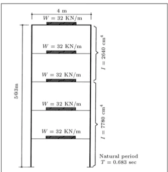
The ve-story steel frame, shown in Figure 1, was designed in accordance with the UBC, where the dead loads on the oors of the frame, the properties of its columns, the second moment of inertia (denoted by
I
as determined to take the base shear according to the UBC) and the natural period of the frame (T = 0:683 sec.) are also reported in the gure. A small modal damping ratio of 2% was considered for all of the modes. Considering both economics and construction constraints, it was assumed desirable to use the same cross-section for the columns of the rst three stories while changing them for the fourth and fth oors, as shown in the gure. After its designing, the frame was subjected to the El Centro (1940, S00E) earthquake, with a Peak Ground Acceleration of (PGA) = 0.348 g, where g = the gravitational acceleration. The peakFigure1. The ve-story frame designed based on UBC. inter-story drift and stress in this case have been found to be 4.23 cm and 674 MPA, respectively. This peak stress is obviously larger than the normal allowable stress of steel, which is about 144 MPA. This is because, in the UBC design, use is made of material non-linearity. Since, in this study, it was desired to design an ATC frame equivalent to the UBC design,
it was assumed that when both of the frames had the same response under the assumption of material linearity, they could be considered equivalent. Again, this seemed a suitable assumption for the present study where a linear control algorithm was used to design the ATC frames. It is possible to use non-linear controllers, such as neuro or fuzzy controllers, which are able to handle non-linear control problems well (Joghataie and Ghaboussi 3], Bani-Hani and Ghaboussi 6]). However, the literature on the subject is still limited and such controllers have been designed only for small frames of up to 3 stories. The subject of non-linear control of larger frames is an issue that could not be considered in this paper.
Hence, the above peak inter-story drift and stress values (4.23 cm, 674 MPA) were, then, also used for the design of an ATC system for the frame.
ATC DESIGN OF THE FIVE-STORY
FRAME
It was decided to control the frame by using only one actuator, which could apply a control force on one of the oors, through prestressed tendons. The frame in Figure 2a, called here the uncontrolled frame, is dierent from that shown in Figure 1, which was designed according to the UBC, since it has now been designed for its dead load only. Hence, the columns are lighter and have smaller lateral stiness
Figure2. The ve-story frame designed for its dead load only (a) Without ATC (b) With ATC where the actuator is on
the ground and connected to the rst oor (c) With ATC, where the actuator is on the ground and connected to the top oor (d) With ATC where actuator is on the fourth oor and connected to the top oor.
in this case, as represented in Figure 2a. Also, the natural vibration period of this frame is T = 0:9228 sec., which is larger than that of the UBC designed frame, which is T = 0:683 sec. Figures 2b to 2d represent 3 dierent alternatives for the placement of the actuator and tendons on the uncontrolled frame.
The methodology and criteria used for the design of an ATC frame, with an equivalent performance to its UBC designed counterpart, is explained here.
Methodology of Integrated ATC Design of
Frames
The El Centro earthquake was assumed appropriate as the design earthquake for the ATC frames of this study. However, in general, design earthquakes should be selected depending on the seismicity of the region, soil properties, etc. For each of the 3 alternatives shown in Figures 2b to 2d, the actuator capacity was selected so that the ATC frames could satisfy the following safe design criteria.
Safe Design Criteria: Using the El Centro 1940 S00E earthquake as the design earthquake, neither the peak inter-story drift nor the peak internal stress in an ATC designed frame should exceed the peak inter-story drift and the peak internal stress in its UBQ designed counterpart, as the allowable maximum drift and stress, respectively.
In all of the cases of Figures 2b to 2d, as well as in the rest of the study, shear frame models were used and the eect of the vertical component of the control force was considered in the determination of the column stresses.
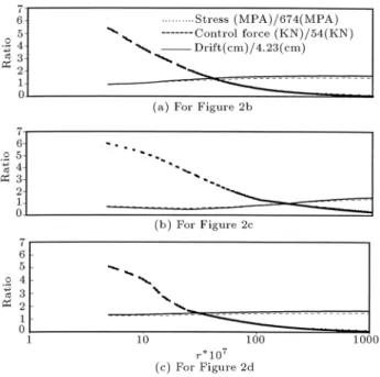
In case (b) of Figure 2, the actuator is installed on the ground and the tendons are connected to the rst oor. For case (c), the actuator is again on the ground but connected to the top of the frame and, nally, for case (d), the actuator is on the fourth oor and is connected to the top of the frame. Figure 3 is a graphical representation of the eect of r, the only instantaneous optimal control parameter, as explained before, on the peak inter-story drift and peak stress and required actuator capacity, which were obtained for each of the cases in Figures 2b to 2d, scaled by dividing to 4.23 cm, 674 MPA and 54 KN, respectively. Hence, the safe design criteria is satised only when the inter-story drift and stress ratios for a given rare less than, or equal to, 1. For each of these cases, anr value was found so that the criteria of a good control, as stated above, was satised with the minimum possible actuator capacity. This resulted in r = 1:67v10
;6 and r = 1:81v10
;5 for cases (b) and (c) of Figure 2, respectively, while, as can be concluded from Figure 3c, an appropriatervalue could not be found for the case of Figure 2d. In cases (b) and (c) of Figure 2, the peak
Figure 3. Eect ofron the maximum drift, stress and
actuator capacity for each of the frames of Figures 2b to 2d when subjected to the El Centro earthquake.
inter-story drift is equal to 4.23 cm, which is equal to the peak obtained in the dynamic analysis of the UBC designed frame subjected to the El Centro earthquake. With this drift, which controlled the design of the ATC system, the peak stress was found to be 613 MPA in both cases, which is less than 674 MPA stress found for the UBC design. The appropriate actuator capacity for each of the cases is: F = 240 KN for case (b) and F = 53 KN for case (c) of Figure 2. As expected, case (c) of Figure 2 is the optimum among the 3 alternatives for the placement of the actuator. Hence, it was selected as the basis for the rest of the study.
Testing the UBC and ATC Frames for Other
Earthquakes
To provide a better understanding of the performance of the UBC and the ATC designed frames, their response to dierent test earthquakes was monitored. Since the El Centro earthquake, with PGA = 0.348 g, was used as the design earthquake, other earthquakes with dierent spectral displacements but with, ap-proximately, the same PGA, were used in testing. To this end, the Parkeld earthquake (1966, S25E) with PGA = 0.347 g and (0.348/1.170) times the Pacoima Dam earthquake (1971, S16E) with PGA = (0.348/1.170)1.170 g = 0.348 g were selected. Also, the response of the frames to a number of sinusoidal ground accelerations of dierent periods in the range of 0.2{2.0 seconds, all with an amplitude of 0.348 g, were studied. Finally, to examine the reserved capacity of the frames, they were subjected to the severe
earthquake of the unreduced Pacoima Dam with PGA = 1.170 g. Results are explained here.
Response to the Parkeld and (0.348/1.170)
Pacoima Dam Earthquakes
Figure 4 represents the time history of the response of the frames to the Parkeld earthquake, which is approximately of the same intensity as that of the El Centro earthquake, but with a signicantly dierent spectral displacement. The dotted, the dashed and the solid lines in Figure 4 represent the peak inter-story drift and stress of the UBC designed frame, the uncontrolled frame designed for its dead load only and the ATC designed frame, respectively. As can be seen, the active controller has been capable of reducing the response of the uncontrolled structure considerably, bringing it closer to that of the UBC. The peak inter-story drift and stress were 1.11 cm and 238 MPA for the UBC frame and 2.15 cm and 380 MPA for the ATC frame, all well below the maximum allowable drift and stress, according to the safe design criteria stated before. For this earthquake, the uncontrolled frame has also performed satisfactorily, according to the safe design criteria for the allowable drift and stress, though marginally. It can be seen that for the ATC designed frame, the peak drift and stress are reduced to about 60% of those of the uncontrolled frame.
The response to (0.347/1.170) the Pacoima Dam
Figure4. Test and comparison between the uncontrolled,
UBC designed and ATC designed ve-story frames when subjected to the Parkeld earthquake.
earthquake is (1.63 cm, 311 MPA) and (2.42 cm, 412 MPA) for the UBC and ATC designed frames, respectively, all well below the allowable values of (4.23 cm, 674 MPA). Again, as in the case of the Parkeld earthquake, the UBC designed frame has performed slightly better from a safety viewpoint. However, the peak acceleration is 1593 cm/s2 for the UBC and 642 cm/s2for the ATC frames, which means that considerably more serviceability is associated with the ATC frame under this earthquake.
Response to the Unreduced Pacoima Dam
Earthquake
Response to the Pacoima Dam earthquake, which is about 3 times that of the El Centro earthquake, is in favor of the UBC designed frame. In this case, the response is (5.49 cm, 780 MPA) for the UBC and (8.36 cm, 1076 MPA) for the ATC frames. Regarding the allowable drift and stress (4.23 cm, 674 MPA), both frames have violated the safety criteria, however, the UBC frame has performed better.
Response to Sinusoidal Ground Accelerations
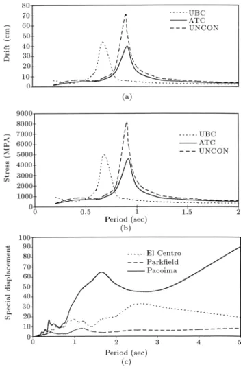
Both frames were subjected to sinusoidal ground accel-erations of dierent vibration periods, between 0.1{2.0 seconds, with 0.348 g amplitude, which is the same as the PGA of the El Centro earthquake. Results shown in Figures 5a and 5b are the peak inter-story drift and acceleration, which, in both cases are plotted against the period of vibration of the ground. As can be seen, both frames suer from resonance in the vicinity of their natural vibration periods, which are 0.683 seconds for the UBC frame and 0.9225 seconds for the ATC frame. The shape and peak of the curves for both frames are considerably similar, though shifted with respect to each other. As expected, it is the spectral displacement of an earthquake that has determined the response of the frames. Figure 5c shows the spectral displacement of the Pacoima Dam, El Centro and Parkeld earthquakes. Focusing on the Pacoima Dam earthquake, it is obvious that the ATC frame is much more susceptible to this earthquake than the UBC frame, due to the larger spectral displacement at its natural vibration period. Also, in Figures 5a and 5b, the response of the uncontrolled frame is represented to show how successful the ATC mechanism has been in its duty, reducing the response of the uncontrolled frame to about 60% at the resonance.
Benet and Cost of Using the ATC Mechanism
The benet of using the ATC over the UBC design has been in the saving of about 6.65 KN of steel used for the columns, at the expense of providing an actuator
Figure5. (a) Maximum drift of the uncontrolled, the
UBC designed and the ATC designed ve-story frames subjected to sinusoidal noises of dierent periods but with the same intensity of 0.347 g (b) Same as (a) but for Maximum Stress (c) Spectral displacement of the El Centro, Parkeld and Pacoima Dam earthquakes.
of 53 KN capacity, plus a cable of approximately 35 m, plus the required sensory system, including the sensors and the transducers, plus the information processing system, which could be a simple chip. Obviously, for the time being, the cost associated with the ATC design is much larger than its benet.
UBC AND ATC DESIGNS OF TEN-,
FIFTEEN- AND TWENTY{STORY
FRAMES
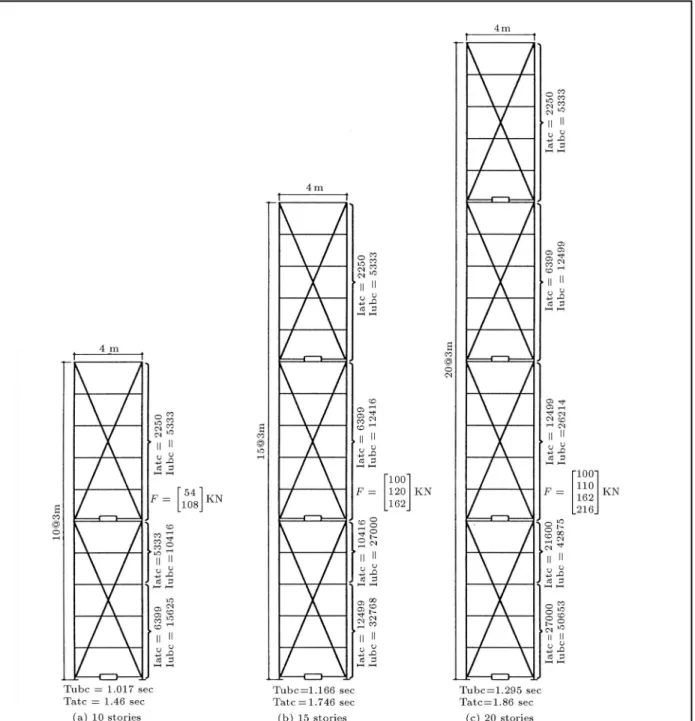
It was desired to study the relationship between the frame height and the actuator capacity for ATC de-signed frames. Hence, rstly, 3 frames of moderate heights of ten, fteen and twenty stories were designed, according to the UBC. Figure 6 contains information about the UBC designed frames, where the stiness of the columns and the natural period of vibration of each frame are also included in this gure. For the
sake of construction ease, it was decided to change the cross-section of the columns at the third, fth oor and every ve oors consecutively. For example, the column sections were changed at the levels of 3, 5, 10 and 15 oors for the twenty{story frame. This resulted in 3, 4 and 5 dierent cross-sections for the columns of the ten-, fteen- and twenty{story frames, respectively. The response in these cases, including the values of the peak inter-story drift and peak stress were (4.45 cm, 665 MPA), (2.81 cm, 476 MPA) and (2.66 cm, 455 MPA) for the ten-, fteen- and twenty{story frames, respectively.
Then, the same frames were redesigned as ATC frames. Again, as for the ve-story frame of the previ-ous section, the columns of each frame were designed to carry its dead load only. Then, ATC mechanisms were added to the frame for its strengthening against earthquakes. The safe design criteria for the peak, inter-story drift and stress in ATC frames, which was explained in the previous sections, was used here also. Again, the El Centro 1940 earthquake was taken as the design earthquake.
It was decided that the actuators should be installed every ve oors, i.e. on the ground, the 5th oor, the 10th oor and so on. This resulted in 2, 3 and 4 actuators for the ten-, fteen- and twenty{ story frames, respectively. This decision was based on personal judgement, which seemed satisfactory at this stage of the work. The authors plan to work on the problem of optimal placement of control mechanisms in future studies.
It was then assumed that the actuators could apply any required force, specied by the controller, without any upper limit on their capacities and, then, the peak value of the control force, applied by each of the actuators during the design earthquake, was taken as its capacity. However, a minimum capacity was specied for the actuators. This minimum actuator capacity, denoted by ACmin, was taken as:
ACmin= AC5W=W5 (7)
where AC5 is the actuator capacity found for the control of the ve-story frame of the previous section = 54 KN, W5 is the weight of the ATC designed ve-story frame = 5 oors 32 KN/m 4 m = 640 KN and W is the weight (KN) of the frame above the oor where the actuator was located. The reason behind this selection of the minimum capacity was that it was assumed, in an ideal situation, that each actuator would control the oors which were located above it. Although more complicated conditions on the minimum capacity could be set forth, this seemed a simple and logical condition. Figure 6 contains information about the capacities of the actuators also. As can be seen, for a specic frame, a combination of
Figure6. Schematics of the ATC designed frames of dierent heights. actuators of dierent capacities has been found to be
appropriate. For the ten-, fteen- and twenty{story frames, the same as for the ve-story frame, the peak inter-story drift has controlled the design, resulting in the following peak response: (4.45 cm, 545 MPA), (2.81 cm, 435 MPA) and (2.66 cm, 419 MPA) for the 10, 15 and twenty{story frames, respectively, recalling that the peak inter-story drift for the ten-, fteen- and twenty{story UBC frames has been 4.45, 2.81 and 2.66 cm, respectively. Also, it is noteworthy that compared to the values reported above for the UBC designed
frames, the maximum stress in the ATC frames is considerably smaller.
RESPONSE TO OTHER EARTHQUAKES
The ten-, fteen- and twenty{story frames, designed using the UBC and the integrated ATC methods, were then subjected to earthquakes other than the design earthquake. To this end, each of the 6 frames, consisting of 3 UBC and 3 ATC designs, were subjected to the same Parkeld and (0:348=1:170) Pacoima
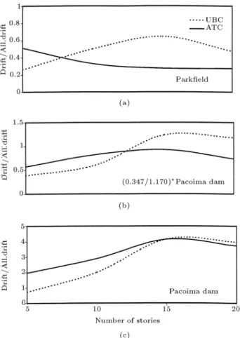
Dam earthquakes. In all of these cases, both the UBC and the ATC designed frames performed pretty similar to each other. The designs were successful. Figures 7a and 7b are for these two earthquakes. In both gures, the horizontal and vertical axes represent the number of oors and the peak inter-story drifts of the ve-ten-, fteen- and twenty{story frames divided by the allowable drift, which is 4.23 cm, respectively. Also, for better representation, the points have been connected by smooth curves. It may roughly be concluded from these gures that the performance of an ATC frame is better than its UBC equivalent when the number of stories is more than 10.
Reserved Capacity of the UBC and ATC
Frames During Severe Earthquakes
Next, for studying UBC and ATC reserved capacities, all their designed frames were subjected to the, severe, unreduced Pacoima Dam earthquake, when all of them violated the safe design criteria.
The peak inter-story drift of the frames, normal-ized to the allowable drift of 4.23 cm, is shown in Figure 7c. Again, the performance of the ATC frame improved, as the number of stories increased.
Figure7. Benet to Cost Ratio (BCR) as a function of
frame height for the ATC designed frames.
ECONOMICS OF ATC AND UBC DESIGNS
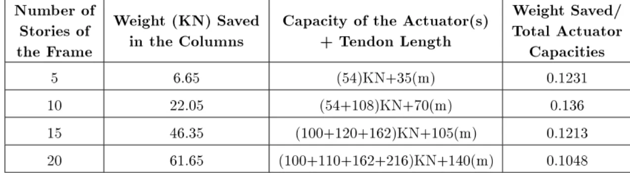
The main goal of this study has been to provide a preliminary qualitative assessment of the cost versus benets associated with the use of the ATC mecha-nism to control frame structures of moderate height, compared with the UBC based designs. Since the technology of the ATC is not yet suciently developed to t the structural needs, it is not possible to provide an exact estimate of the cost required for its use in the control of frames against earthquake loading. However, as one of the results of this study, the reduction in the total column weight of the ATC designed frames, as the main benet of using the ATC mechanism, on the one hand, and the required actuators capacity, plus the approximate tendon length, as a measure of its cost, on the other hand, are reported in Table 1. The rst column represents the number of stories of the frame, while the second and third columns show the benet and cost of using the ATC mechanism. Also, if the value of the saved weight divided by the total capacity of the actuators, as represented in the fourth column, is considered as a logical measure of the Benet to Cost Ratio (BCR) for the ATC design, it can be seen that it is approximately constant for frames of dierent heights of up to 20 oors. Generalization of this result to taller frames requires more study of the subject, noting that wind loading is often more decisive than earthquake loading for tall frames. Figure 8 represents BCR as a function of the number of stories graphically.
SUMMARY AND CONCLUSIONS
The economics associated with a fully active tendon controlled frame (ATC frame) design of up to twenty stories was studied in this paper. As a rst step, a methodology for the design of the ATC frames was presented, so that they could behave similar to their UBC designed counterparts and, hence, could become considered as their equivalent. To this end, rst, a
Figure 8. Comparing the performance of the UBC and
ATC frames of dierent heights based on their response to two test earthquakes of Parkeld and Pacoima Dam, with their maximum drifts observed during the occurrence of the earthquakes normalized by their division to the allowable drift (a) Parkeld, (b) Pacoima Dam.
Table1. Benet and cost of using ATC mechanism in the design of ATC frame equivalent to their UBC designed
counterparts for ve-, ten-, fteen- and twenty{story frames.
Number of
Stories of
the Frame
Weight (KN) Saved
in the Columns
Capacity of the Actuator(s)
+ Tendon Length
Weight Saved/
Total Actuator
Capacities
5 6.65 (54)KN+35(m) 0.1231
10 22.05 (54+108)KN+70(m) 0.136
15 46.35 (100+120+162)KN+105(m) 0.1213
20 61.65 (100+110+162+216)KN+140(m) 0.1048
safe design criterion for ATC frames was proposed. The criterion states that under the eect of a specied design earthquake, for example, the El Centro 1940 S00E earthquake, neither the peak inter-story drift nor the peak stress in an ATC designed frame should exceed the peak inter-story drift and stress in its UBC designed counterpart, respectively.
Then, through numerical studies and using the instantaneous optimal control algorithm, a number of ve, ten-, fteen- and twenty{story ATC frames were designed, according to the safe design criteria. A min-imum actuator capacity was specied as a constraint on the selection of the required actuators.
It was observed that the designed ATC frames exhibited a similar performance to their UBC designed counterparts, not only under the design earthquake (here the El Centro earthquake) but also, for two other test earthquakes of dierent spectral density but of similar peak ground acceleration to that of the design earthquake. These two test earthquakes were the Parkeld (1966) and the reduced Pacoima Dam (1971). Also, to study the reserved capacity of the UBC and ATC frames to withstand severe earthquakes, the unreduced Pacoima Dam earthquake, with a PGA of about 3 times that of the El Centro earthquake, was applied to the frames. Both the UBC and ATC frames violated their allowable drift and stress limits. However, the performance of the ATC design was better for taller frames.
The ratio of benet to cost (BCR) of an ATC design was dened as the ratio of the weight saved in the material divided by the total capacity of the actuators. It was found that BCR was approximately constant for all of the frames in this study, i.e., frames of up to twenty-stories high. Generalization of this result to taller frames requires more research.
Also, although it was found that it is not eco-nomical to consider ATC design of frames as a suitable substitute for the conventional UBC design for the time being, the authors do hope and believe that studies like this could provide more information to look at active control of structures from a practical viewpoint, to try
to nd ways to make its technology cheaper and bring it closer to real world applications.
ACKNOWLEDGMENT
This research has been partially supported by the National Research Council of Iran, Grant number 5064. The rst author would like to acknowledge this support. Furthermore, the cooperation of the Civil Engineering Department of Sharif University of Technology, Tehran, I.R. Iran, during this research, is greatly appreciated.
REFERENCES
1. Leipholz, H.H.E. and Abdel-Rohman, M., Control of Structures, Martinus Nijho Publishers (1986). 2. Soong, T.T., Active Structural Control: Theory and
Practice, Longman Scientic and Technical (1990). 3. Joghataie, A. and Ghaboussi, J. \Neural networks and
fuzzy logic in structural control", Proceedings of the First World Conf. on Struct. Control, 3-5 Aug., LA, CA, USA, pp WP1-21-30 (Aug. 1994).
4. Ribakov, Y. and Gluck, J. \Active control of MDOF structures with supplemental electrorehological uid dampers",Earthquake Engineering and Structural Dy-namics,28, pp 143-156 (1999).
5. Joghataie, A. and Vahidi, A. \Designing a general neurocontroller for water towers", ASCE, J. Engrg. Mech.,126, pp 582-587 (2000).
6. Bani-Hani, K. and Ghaboussi, J. \Nonlinear structural control using neural networks",ASCE, J. Engineering Mechanics,124(3), pp 319-327 (1998).
7. Casciati, F., Ed., Third World Conference on Struc-tural Control (3WCSC), 7-12 April 2002, Como, Italy, by John Wiley and Sons (2002).
8. Bossens, F. and Preumont, A. \Active tendon control of cable-stayed bridges: A large scale demonstration",
Earthquake Engineering and Structural Dynamics,30,
9. Soong, T.T. \Experimental simulation of degrading structures through active control", Earthquake En-gineering and Structural Dynamics, 27, pp 143-154
(1998).
10. Johnson, E.A., Voulgaris, P.G. and Bergman, L.A. \Multiobjective optimal structural control of the Notre Dame building model benchmark",Earthquake Engi-neering and Structural Dynamics, 27, pp 1165-1188
(1998).
11. Spencer, B.F. and Sain, M.K. \Controlling buildings: A new frontier in feedback", IEEE Control Systems, pp19-35 (Dec. 1997).
12. UBC, Uniform Building Code, Structural Engrg. De-sign Provisions,2, Chapter 16, Div. 1 (1997).
13. Yang, J.N., Akbarpour, A. and Ghaemmaghami, P. \New control algorithms for structural control",ASCE J. Engineering Mechanics,113, pp 1369-86 (1987).