Performance Analysis of Per Tone
Equalization in DMT-Based Systems
S.S. Changiz Rezaei 1
and M.R. Pakravan
The Per Tone equalization algorithm is a novel discrete multitone (DMT) equalization method with practical applications in subscriber digital loop systems. Unlike time domain DMT equalizers (TEQ), which equalize all DMT tones in a combined fashion, the Per Tone equalizer equalizes each tone separately. In this paper, the performance and complexity of this technique is investigated and compared with that of other TEQs. Furthermore, the behavior of this technique in dierent simulation conditions, such as over dierent standard CSA loops and in the presence of additive white Gaussian noise with variable power spectral density level and near end crosstalk (NEXT), is studied and compared with that of other TEQs. Simulation results show that Per Tone has a reduced sensitivity to synchronization delay and a much better performance compared to other conventional DMT equalizer design algorithms.
INTRODUCTION
In a DMT transceiver, designing an appropriate equal-izer has a profound eect on maximizing the achievable bit rate. This fact makes the equalization problem in DMT-based systems an important determining fac-tor [1,2]. Besides the achievable bit rate, the computa-tional complexity of an equalization method is another parameter that should be considered in the evaluation of a particular algorithm. So, this paper evaluates dierent DMT equalization methods and a Per Tone equalization through an extensive performance and complexity study and comparison.
DMT equalization methods can be divided into conventional and novel schemes. Conventional DMT equalizer structures consist of a real multi-tap time domain equalizer (TEQ) (before demodulation with FFT) combined with a complex 1-tap frequency do-main equalizer (FEQ) per tone (after demodulation with FFT). Conventional equalization in DMT-based systems can be subdivided into 4 general groups: 1. Minimum Mean Squared Error (MMSE) [3,4], 2. Maximum Shortening SNR (MSSNR) [5,6],
1. Department of Electrical Engineering, Sharif University of Technology, Tehran, I.R. Iran.
*. Corresponding Author, Department of Electrical Engi-neering, Sharif University of Technology, Tehran, I.R. Iran.
3. Maximum Geometric SNR (MGSNR) [7], 4. Maximum Bit Rate (MBR) [7,8,9].
As stated above, in evaluating dierent equalization methods, performance and complexity should be con-sidered together - a fact that is not covered in the literature. The main contribution of this paper is providing a unied insight into the eld of DMT equalization by comparing dierent DMT equalization methods (main time domain equalization algorithms and Per Tone). Comparison is done by evaluating both their performances in dierent simulation conditions (a comprehensive performance evaluation) and their com-putational complexities (both initialization complexity and complexity during data transmission).
This paper is organized as follows. In the follow-ing section, the complexity of Per Tone equalizer and conventional DMT equalizer design algorithms during data transmission and initialization are studied and compared with each other. Then, the performance of Per Tone equalization, such as achievable bit rate, sensitivity to synchronization delay and NEXT, is compared with that of conventional DMT equalizer methods. The last section concludes the paper.
COMPLEXITY ANALYSIS
In this section, the computational complexity of the Per Tone equalizer is compared with that of conventional
DMT equalizers. Notations used in this complexity analysis are dened in Table 1.
Since Per Tone equalization is performed at a down sampled rate, with respect to conventional DMT equalizers, its complexity during data transmission is the same as that of TEQ design algorithms.
The computational complexities during data transmission of a standard TEQ and a modied Per Tone equalizer are calculated in Tables 2 and 3, re-spectively. The last rows of these tables are calculated when the number of used tones areN
u=
N=2 and the symbol duration is N=F
s. It is concluded from these tables that complexities during data transmission are the same and of orderF
s
T [10,11].
On the other hand, as will be shown in the sequel, the computational complexity of Per Tone direct initialization methods is prohibitively high. The computational complexity of dierent Per Tone di-rect initialization methods can be estimated as fol-lows.
Classical MMSE Solution
v
i=E n
(
u
(k ) i ) Hu
(k ) i o 1 E n(
u
(k ) i ) H( X k i) o :Table 1.
Notations and their denitions. NNo. of samples in a DMT symbol and hence the IFFT/FFT size Fs Sampling frequency
T No. of equalizer taps Cyclic prex length
As mentioned before, in this method, Per Tone equal-izer coecients are obtained by the above formula.
u
(k )i is the input vector for the equalizer for the ith tone, consisting ofith FFT output for thekth DMT symbol and T 1 real dierence terms, and X
k i is the
ith desired subsymbol in the kth signaling interval. It is noteworthy that, due to the special structure of Per Tone, calculating a matrix inverse for each tone is not necessary here.
Consider the following formula for each tone,i: (
u
(k )i ) H=
y
y
k i=
F
i(HX
+n
) =G
iX
+N
i ; whereu
(k )i is the input vector for each tone in time k. In the Per Tone equalizer, this vector consists ofT 1 real dierence terms (
y
) and the FFT output for each tone, i. In the above formula, the rst T 1 rows of matrixG
i are denoted by the indexdi. Now, the input autocorrelation matrix can be written as follows:
E n
(
u
(k ) i ) Hu
(k ) i o =D d
id
H i i ; where:D
=E n(
Di
(k ))H(
Di
(k ))o =
G
diR
xxG
H di+ 2
2 N
I
T 1 :
In which, the (T 1)(T 1) real matrix
Di
(k ) is associated withy
part ofu
(k )i ,
d
i is a (T 1)1 column vector and
i is a scalar.
Table 2.
Computational complexity of aT-tap TEQ during data transmission.# Multiplications
# Additions
TEQ
FsT Fs(T 1)FFT
FsO(N:log(N))=(N+) FsO(N:log(N))=(N+)FEQ Polar
Representation
N uF s
=(N+) N
u F
s
=(N+)
TEQ + FEQ
Fs(T+Nu=(N+)) Fs(T 1 +Nu=(N+))Approximation
Fs(T+ 1=2) Fs(T 1=2)Table 3.
Computational complexity of a modiedT-tap Per Tone equalizer during data transmission.# Multiplications
# Additions
TEQ
FFT
Fs
O(N:log(N))=(N+) F s
O(N:log(N))=(N+)
FEQ Cartesian
Representation
NuFs[4 + 2(T 1)]=(N+) = 2FsNu(T+ 1)=(N+)NuFs[2 + 2(T 1)]=(N+) +F
s(
T 1)=(N+) =Fs(2NuT+T 1))=(N+)
Approximation
F s(T+ 1) F
s T+F
s(
Now, the inverse of the input autocorrelation matrix can be written as follows:
E n
(
u
(k ) i ) Hu
(k ) i o 1 =B
ib
ib
ii
:
By considering the fact that each matrix multiplied by its inverse is equal to matrix unity, one has:
P
i=D
1d
i ; i= 1 id
H iP
i ;b
i=P
ii
;
B
i=
D
1
b
i
P
H i:
Now, the computational complexity of this method can be calculated, as in Table 4.
Table 4.
Computational complexity ofT-tap Per Tone initialization, based on the classical MMSE method.Flop Count
D
1O(T 3)
P
iO(8T 2)
i
O(8T)
b
iO(6T)
B
iO(T 2+ 8
T)
Total Flop Count
O(NT 3+ 9NT 2+ 23
NT)
Solving a Least Squares Problem, Based on
Channel and Noise Estimates
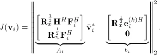
In this method, the following cost function should be minimized [10].
J(
v
i) ="
R
1 2 xH
H
F
H iR
1 2 nF
H i #| {z }
A i
v
i "R
1 2 xe
(k )H i0
#| {z }
bi 2 2 :
As is obvious from the above cost function, rst, the Cholesky factors of matrices (
R
x)3N3N and (R
n)(N+T 1)(N+T 1), i.e
R
1 2x and
R
1 2n, should be calculated. After that, the least squares problem is solved by means of either QR decomposition or SVD computation of matrix
A
i. The total op count (num-ber of additions and multiplications) of this method is calculated in Tables 5 and 6.Table 7 compares the initialization complexity of dierent DMT equalization methods with that of Per Tone direct initialization methods.
By substituting FFT/IFFT, size N = 512, the number of equalizer taps,T = 24 and the cyclic prex length, v = 32, the complexities are calculated as in Table 8. It can be inferred from Tables 7 and 8 that the complexity of Per Tone direct initialization methods
Table 5.
Computational complexity ofT-tap Per Tone initialization based on QR decomposition.Cholesky Factorization
O( (3N) 3 3 + (N+T 1) 3 3 )opsQR Decomposition
O(2(4N+T 1) 2+ (4N 1)N)ops
Total Flop Count
O( (3N)3 3 +
(N+T 1) 3 3 + 2(4
N+T 1) 2+ (4
N 1)N)ops
Table 6.
Computational complexity ofT-tap Per Tone initialization, based on SVD computation.Cholesky Factorization
O( (3N) 3 3 + (N+T 1) 3 3 )opsSVD Computation
O(4(4N+T 1) 2NT 2+ 22
NT 4)ops
Total Flop Count
O( (3N)3 3 +
(N+T 1) 3 3 + 4(4
N+T 1) 2
NT 2+ 22
NT 4)ops
Table 7.
Initialization computational complexity of dierent DMT equalization methods and the Per Tone equalizer (PTEQ).DMT Equalization Design
Flop Count
MMSE, UTC O(
1 3
3+
2+ 2 T+T
2)
MMSE, UEC O(
2+ 2 T+ 2T
2)
MSSNR O(T
3)
Min-ISI O(5NT +T
3)
MGSNR O(T
2+ T 2+ T 2+ 3)
QR-PTEQ O(
(3N) 3 3 +
(N+T 1) 3 3 + 2(4
N+T 1) 2+ (4
N 1)N)
SVD-PTEQ O(
(3N) 3 3 +
(N+T 1) 3 3 + 2(4
N+T 1) 2+ (4
N 1)N)
MMSE-PTEQ O(NT
3+ 9 NT
2+ 23 NT)
is prohibitively high. This is the motivation for proposing appropriate adaptive initialization methods for Per Tone initialization in [12,13]. (Adaptive Per Tone initialization methods have a lower initialization complexity than direct ones.) Here, the complexity cal-culations of adaptive Per Tone initialization algorithms are brought from [12,13], as follows:
1. Normalized LMS: (T 2 +
N
2 (4T+ 7)) F
s N ; (T 1 +
N
2 (4T+ 8)) F
s N : 2. RLS:
(T 1)(3T+ 2)
2 +
N
2 (12T+ 4)
F s N ;
(T 1)(6T+ 8)
2 +N
2 (20T+ 10)
F s N
: 3. RLS-LMS:
(T 1)(3T+ 2)
2 +
N
2 (4T+ 6)
F s N ;
(T 1)(6T+ 8)
2 +
N
2 (4T+ 9)
F s N :
Furthermore, for the purpose of comparison with other DMT equalization methods, the above quantities are calculated, as in Table 8, in terms of op count per update (with the same number of taps and conditions stated above).
SIMULATION RESULTS
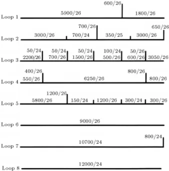
In this section, Per Tone performance is compared with that of conventional DMT equalizers over dierent standard CSA loops. The congurations of 8 standard CSA loops are shown in Figure 1. In the simulation, X
k
i is the transmitted 2-bit constellation in tone iin thekth DMT symbol. Simulations were performed on standard CSA loops, with an additive white Gaussian noise of -140d Bm/Hz. The system cross talk is assumed to be coming from NEXT and is modeled assuming 24 same-binder ADSL disturbers. Optimal synchronization delay is = 0. FFT/IFFT size N, cyclic prex length and sampling frequency are 512, 32
Figure 1.
Conguration of the eight standard CSA loops. Numbers represent length/thickness in feet per gauge. The vertical lines represent bridge taps.Table 8.
Computational complexity of dierent DMT equalization methods and the Per Tone equalizer (PTEQ).DMT Equalization Design
Flop Count
MMSE, UTC O(1:410
4)
MMSE, UEC O(3:710
3)
MSSNR O(1:410
4)
Min-ISI O(1:710
4)
MGSNR O(4:510
4)
QR-PTEQ O(1:310
9)
SVD-PTEQ O(1:310
9)
MMSE-PTEQ O(10
7)
Adaptive Per Tone
Flop Count Per Update
NLMS PTEQ O(5:310
4)
SR-RLS PTEQ O(210
5)
RLS-LMS PTEQ O(5:610
Table 9.
Achievable bit rate for 6 DMT equalizations over 8 standard CSA loops.Equalizer Per Tone UTC UEC MSSNR MBR MIN-ISI
Loop No.
(kbps) (kbps) (kbps) (kbps)
(kbps)(kbps)
CSA#1 11180 7236 9704 10484 10364 10328
CSA#2 11468 9956 9960 11088 11236 11220
CSA#3 11064 9032 9056 10684 10588 10572
CSA#4 11220 7016 9100 10312 10508 10532
CSA#5 11188 8672 8668 10668 10704 10720
CSA#6 11000 9664 9620 9952 10008 10032
CSA#7 10832 9704 9388 9888 9944 9948
CSA#8 10378 9244 9212 9660 9592 9600
and 2.208MHz, respectively. Noise Margin and coding gain are set to 6dB and 3dB, respectively.
Table 9 compares the maximum achievable bit rate of 6 dierent DMT equalizers with 24 taps, each in the presence of additive white Gaussian noise with a level of -140d Bm/Hz and NEXT over 8 standard CSA loops. It can be concluded from this table that the bit rate achieved by means of the Per Tone equalizer is higher than that achieved by means of other DMT equalizers over all types of standard CSA loops. Furthermore, the bit rate achieved by means of MBR is almost the same as the one achieved by means of MIN-ISI and this bit rate is the closest of all to the one achieved by means of the Per Tone equalizer.
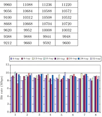
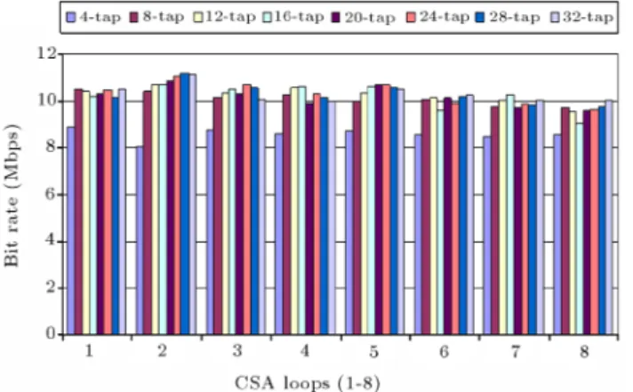
Figures 2 to 7 show the performance of dierent DMT equalizers versus equalizer taps. It can be seen that Per Tone(unlike other DMT equalizer methods) behaves predictably against the number of equalizer taps. The more the number of Per Tone taps, the more the achievable bit rate.
The eect of white Gaussian noise on the per-formance of dierent DMT equalizers (with 24 taps each) is studied over CSA#4 in Figure 8 (There is not any NEXT here). This gure shows that the bit
Figure 2.
Achievable bit rate over 8 standard CSA loops for Per Tone equalization.Figure 3.
Achievable bit rate over 8 standard CSA loops for UTC equalization.Figure 4.
Achievable bit rate over 8 standard CSA loops for UEC equalization.rate achieved by means of Per Tone is higher than the one achieved by means of conventional DMT equal-izers at dierent additive white Gaussian noise PSD levels. Important to note is the fact that in low noise environments, in which ISI/ICI is dominant, Per Tone performance is much better than that of conventional DMT equalizers, while, when noise PSD level is high, Per Tone behaves just like other conventional TEQ
Figure 5.
Achievable bit rate over 8 standard CSA loops for MSSNR equalization.Figure 6.
Achievable bit rate over 8 standard CSA loops for MBR equalization.Figure 7.
Achievable bit rate over 8 standard CSA loops for MIN-ISI equalization.design methods. This highlights Per Tone's strength in combating ISI and ICI.
Figure 9 compares 8 and 32-tap Per Tone equal-izer sensitivity to synchronization delay with that of a 32-tap MMSE-UTC equalizer over CSA#1. It is seen that the bit rate achieved by means of the Per Tone equalizer is signicantly smoother than the one achieved by means of MMSE-UTC. Furthermore, this
Figure 8.
Achievable bit rate versus AWGN PSD level for UTC, UEC, MSSNR, MBR, MIN-ISI, and Per Tone equalizers over CSA#4.Figure 9.
Achievable bit rate versus synchronization delay for Per Tone and UTC equalizers over CSA#1.sensitivity is more reduced by increasing equalizer taps in the Per Tone equalizer. Figures 10 to 12 also show the eect of synchronization delay on the SNR distribution over CSA#1 for an 8 and 32-tap Per Tone and an 8-tap MMSE-UTC equalizer. These gures also represent Per Tone reduced sensitivity to synchronization delay.
Furthermore, these gures show that the SNR distribution in the Per Tone equalizer, unlike TEQ design algorithms, does not suer from undesirable dips. This comes from the fact that, in TEQ design methods, all tones are equalized in a combined fashion, while, in the Per Tone equalization method, a suitable equalizer is designed for each tone separately and control over the frequency response is achieved by performing the equalization entirely in the frequency domain.
Figure 10.
SNR distributions for 8-tap UTC equalization in delay range [0:10:85] over CSA#1.Figure 11.
SNR distributions for 8-tap Per Tone equalization in delay range [0:10:85] over CSA#1.Figure 12.
SNR distributions for 32-tap Per Tone equalization in delay range [0:10:85] over CSA#1.Figure 13.
Rate versus reach for 24-tap Per Tone.Figure 14.
Rate versus reach for 24-tap UTC.Figure 16.
Rate versus reach for 24-tap MSSNR.Figure 17.
Rate versus reach for 24-tap MBR.Figure 18.
Rate versus reach for 24-tap MIN-ISI.the performance of Per Tone with that of dierent DMT equalizer methods. Simulations are done in ADSL downstream over a 26AWG loop with variable length and without a bridge tap. These gures show that, among DMT equalizers, UTC and UEC have the lowest sensitivity to NEXT, while the sensitivity of Per Tone is the highest of all. Figure 13 shows that the achievable bit rate by Per Tone becomes zero in the loop length of 32 kft, while this value reduces to 28 kft by means of UTC and UEC and to 30 kft by means of MSSNR, MBR and MIN-ISI (Figures 14 to 18).
CONCLUSION
The novel Per Tone equalization presented in [10] is based on transferring the TEQ operation into the frequency domain. This leads to gaining control over the frequency response and, consequently, a higher achievable bit rate than conventional TEQ methods.
Another Per Tone advantage over conventional DMT equalizers is its predictable behavior against the number of equalizer taps. As simulation results showed in the previous section, by increasing the number of equalizer taps, Per Tone performance, in terms of maximum achievable bit rate and sensitivity to synchronization delay, improves.
Besides the unique advantages of Per Tone, it suers from some disadvantages, such as high mem-ory requirement and computational complexity during initialization. Furthermore, as shown by the simulation results, Per Tone's sensitivity to crosstalk is high.
To reduce the computational complexity of Per Tone initialization, Acker et al. [12] and Ysebaert et al. [13] have proposed the idea of applying an adaptive ltering algorithm for Per Tone initialization. As Acker et al. [12] state, applying the LMS algorithm for Per Tone equalization is not suitable, since, although this algorithm is the most appropriate one from the com-putational complexity point of view, its convergence rate is the slowest of all. On the other hand, the RLS adaptive ltering algorithm, which is characterized by a high convergence rate, is not computationally ecient. Hence, Ysebaert et al. [13] suggest a combined RLS-LMS adaptive Per Tone equalization and claim that this method combines the desirable features of both the LMS and the RLS adaptive ltering algorithm, i.e., computational eciency and high convergence rate, in a downstream case. However, Per Tone adaptive initialization in ADSL upstream is still an open problem.
Moreover, due to the high sensitivity of Per Tone to crosstalk, combining Per Tone equalization and crosstalk cancellation, as proposed in [14], seems quite helpful. Working on the concept of combined Per Tone equalization and crosstalk cancellation becomes
more important when complexity reduction is taken into account.
It should be noted that the work on DMT equal-ization continues and other new methods are being introduced. As an example, another DMT equalization algorithm, called TEQ-Filter Bank, has been proposed in the literature [15] and appears to achieve a good bit rate performance compared to the algorithms discussed in this paper.
ACKNOWLEDGMENT
This work was supported by the Iran Telecommunica-tion Research Center (ITRC).
REFERENCES
1. Starr, T., Cio, J.M. and Silverman, P., Understand-ing Digital Subscriber Line Technology, Prentice Hall, TR (1999).
2. Bingham, J.A.C.,ADSL, VDSL and Multicarrier Mod-ulation, John Wiley & Sons Inc. (2000).
3. Chow, J. and Cio, J.M. \A cost-eective maximum likelihood receiver systems",International Conference on Communication (ICC1992), Chicago, USA pp 948-952 (1992).
4. Al-Dhahir, N. and Cio, J.M. \Eciently computed reduced-parameter input-aided MMSE for ML de-tection: A unied approach", IEEE Transaction of Information Theory,
42
, pp 903-915 (1996).5. Melsa, P.J.W., Younce, R.C. and Rohrs, C.E. \Impulse response shortening for discrete multitone transceivers", IEEE Transaction on Communication,
44
(12), pp 1662-1672 (1996).6. Yin, C. and Yue, G. \Optimal impulse response short-ening for discrete multi-tone transceivers",Electronics Letters,
3
, pp 1632-1636 (2000).7. Al-Dhahir, N. and Cio, J.M. \Optimum nite-length equalization for multicarrier transceivers",
IEEE Transaction on Communication,
44
, pp 56-64 (1996).8. Arsalan, G., Evans, B.L. and Kiaei, S. \Equalization for discrete multitone transceivers to maximize bit rate",IEEE Transaction on Signal Processing,
49
, pp. 3123-3135 (2000).9. Martin, R.K., Vanbleu, K., Ding, M., Ysebaert, G., Milosevic, M., Evans, B.L., Moonen, M. and Johnson, C.R., Jr., \Unication and evaluation of equalization structures and design algorithms for discrete multitone modulation systems", IEEE Transactions on Signal Processing,
53
, pp 3880-3894 (2005).10. Acker, K.V., Moonen, M., Wiel, O.V. and Pollet, T. \Per Tone equalization for DMT-based systems", IEEE Transaction on Communication,
49
, pp 109-119 (2001).11. Pollet, T. and Peeters, M. \Equalization for DMT-based broadband modems", IEEE Communication Magazine, pp 106-113 (2002).
12. Acker, K.V., Leus, G., Moonen, M. and Pollet, T. \RLS-based initialization for per tone equalizers in DMT-receivers",Proceedings of European Signal Pro-cessing Conference, Tampere, Finland (2000). 13. Ysebaert, G., Vanblue, K., Cuypers, G., Moonen,
M. and Pollet, T. \Combined RLS-LMS initialization for Per Tone equalizers in DMT-receivers", IEEE Transaction on Signal Processing,
51
, pp 1916-1927 (2003).14. Vanbleu, K., Ysebaert, G., Moonen, M. and Vandaele, P. \Combined equalization and alien crosstalk cancel-lation in ADSL receivers",Proceedings of the European Signal Processing Conference (EUSIPCO), Toulouse, France, 3-6 September 20 (2002).
15. Ding, M., Shen, Z. and Evans, B.L. \An achievable performance upper bound for discrete multitone equal-ization", Proceeding of IEEE Global Telecommunica-tion Conference 2004 (GLOBECOM '04),