Sharif University of Technology
Scientia IranicaTransactions B: Mechanical Engineering www.scientiairanica.com
Research Note
Visualization and analysis of nano-manipulation in
liquid environment with atomic force microscopy
S. Esmaeilzadehha
aand M.H. Korayem
b;a. Department of Mechatronics Engineering, Science and Research Branch, Islamic Azad University, Tehran, Iran.
b. Robotic Research Laboratory, Center of Excellence in Experimental Solid Mechanics and Dynamics, School of Mechanical Engineering, Iran University of Science and Technology, Tehran, Iran.
Received 14 February 2013; received in revised form 14 December 2013; accepted 17 June 2014
KEYWORDS Visualization; Nano-manipulation; Atomic force microscopy; Liquid forces.
Abstract. This paper focuses on theoretical analysis of AFM based nano-manipulation in a liquid environment. To achieve this goal, major forces in the liquid environment were reviewed and the manipulation processes were modelled by introducing the eect of intermolecular and hydrodynamic forces. The dynamic behaviour of pushing a gold nano-particle of 50-nm radius on a silicon substrate at a velocity of 100 nm/s was investigated. A virtual reality user interface was also implemented and evaluated in a liquid environment, so users can get a sense of the forces. The results show that, in comparison to air, the required forces and time are increased by 2 and 6.5% for sliding and 2 and 4.3% for rolling in a liquid environment. Furthermore, for various submerged lengths of the cantilever in water, forces and time values are varied at 8 and 10.5%, respectively. Based on simulation results, sliding occurs at nominal values and critical forces and manipulation times in the liquid environment increase over the values. For biological manipulation purposes, the liquid environment is superior in comparison to air and the obtained results are veried by existing experiments.
© 2014 Sharif University of Technology. All rights reserved.
1. Introduction
AFM is an eective tool for studying molecular sub-strates [1]. AFM is a simple nano-manipulator used for nano-particles moving, riding on surfaces, cutting, perceiving, nicking, lifting and displacement. Figure 1 depicts the function of the AFM graphically.
Since a human operator cannot sense the nano-world directly, tele-operation between micro and macro systems in the nano-world [2] could be an alternative solution to forwarding perception to the operator. This operation is implemented in a virtual reality medium. Virtual reality is a medium for imagination, manipu-lation and contact with simulated environments. In
*. Corresponding author. Tel./Fax: +98 21 44865239; E-mail address: [email protected] (M.H. Korayem)
this paper, nano-manipulation in a liquid environment with forces applied on the cantilever tip is shown in a perceptible sense, graphically. These forces include horizontal and vertical cases.
Much research has been carried out on nano/micro manipulation in liquid environments. Savia et al. [3] proposed a numerical method to estimate adhesion forces. Mori showed that the adhesion force between a glass particle and a hydrophilic plate increases with relative humidity due to strong capillary condensation [4]. Theande et al. [5] performed force and friction measurements using atomic force microscopy and the colloidal probe technique in a liquid environment at dierent concentrations of sodium oleate. Drummond and Israelachvili [6] studied the wettability of rock surfaces. They measured the interactions between
Figure 1. Manipulation using an AFM probe as a nano-manipulator.
dierent materials in contact and established their implications on the observed wetting behavior. Noy et al. [7] performed a comparison of measuring forces in ultra-high vacuums, liquids, and ambient air.
Butt [8] described the technique of AFM force measurement and analyzed force curves obtained under dierent conditions. Grierson and Flater [9] discussed nano-scale adhesion determination and friction prop-erties between solids. Putman et al. [10] has shown that standard cantilevers can be used for tapping mode AFM in air, and successfully used a cantilever for the tapping mode AFM in liquid. Goryacheva and Makhovskaya [11] developed an analytical solution to analyze the inuence of the adhesion interaction potential and volume of liquid. Lokar and Ducker [12], on the other hand, used a thermodynamic argument to predict the adhesion between two solid surfaces. Liang et al. [13] briey reviewed the theories of the colloidal forces between particles and surfaces, including van der Waals forces, electrical double layer forces, salvation forces, hydrophobic forces and steric forces.
Luckham [14] gave examples of direct measure-ments of van der Waals, electrical double layer and steric forces, and showed how they can be modied and aect the properties of bulk suspensions. Carine et al. [15] developed a detailed theoretical model of the experimental setup, which accounts for surface forces, hydrodynamic interactions, droplet deformation, and AFM cantilever deection. Jones [16] discussed and compared the interaction between cantilever, substrate and uid, while generating force curves, and theoretical models for squeeze-lm eects and drag on the SPM cantilevers were quantied. Bonaccurso [17] reviewed experimental work on conned Newtonian and non-Newtonian liquids using the AFM. Shen [18] presented a new understanding of adhesion and anti-adhesion of a liquid to a solid surface under dynamic conditions. The eect of disjoining pressure between a rigid spherical probe particle and a liquid interface was studied by Chan [19]. Resch [20] controlled manipulation of individual gold nano-particles in liquid environments
using the tip of a scanning force microscope for the rst time, and Best [21] studied single-molecules, and compared them both, quantitatively and qualitatively, to those derived from conventional protein folding studies.
Seantier focused on AFM high resolution imaging of transmembrane proteins in model and native mem-branes [22]. Neto provided a review of experimental studies regarding the phenomenon of slip of Newtonian liquids at solid interfaces, and dedicated particular attention to eect factors such as surface roughness. Gauthier [23] presented an overview of the micro forces in air and liquid and then introduced a review of the major dierences between dry and submerged micromanipulations. He gives an experimental analysis of the physical phenomena at a microscopic scale in dry and liquid media [24]. At this scale, the molecules of the water are not perceptible, whereas, by moving the probe in the nano-scale molecules, they become observable and can be followed graphically.
This paper is organized as follows. First, the forces in the liquid environment and the manipulation of nano-particles are modelled. Next, the manipulation of the nano-particles in liquid medium is visualized. Then, the results of simulation are analysed and discussed.
2. Nanomanipulation modelling in liquid medium
In this study, nano-particles with a radius of Rp are
modelled. Particles are absorbed in the base plate and moved through the AFM probe under uid conditions. Dierent steps are considered in nano-manipulation of the particle movement. Liquid forces are divided into two groups including intermolecular forces and hydrodynamic forces. Applied forces in the liquid environment have two forms; molecule reaction forces and macro forces. Intermolecular forces include surface tension, electrostatic double layer force, squeeze lm force, solvation force, hydration force, steric force and adhesion force.
When the AFM probe is submerged in liquid, contact between the liquid surface and the cantilever occurs. The cantilever moves to push the particle, and the liquid surface stretches and resists movement. To overcome this eect, dW , which is proportional to the increase in surface area, dA [23], is applied. Introducing the proportional constant, , we have, in Eq. (1):
dw = :dA: (1)
Constant is called surface tension, b is the perimeter of the cantilever and the force can be calculated in Eq. (2):
Since, the water is a high dielectric uid, absorption and defusion of the charge in it is high. Ions and the surfaces with electrical charges make an electrical layer. When an opposite area (charge with both signs) is close to it, then ions will be increased among the layers and make a repulsing force. This force decreases at high distances, strongly [6]. The relation between the potentials and closing time is as follows: ( = x) = 2, ( = 0) = 1. The force rate is also dened
as the following in Eq. (3):
Felcp=2R"" 0
D
h
2 S Te D=D ( S2+ 2T)e 2D=D
i : (3) Once the cantilever nears the surface, relative to its width, squeeze-lm eects between the cantilever and substrate dominate the force response of the can-tilever [16]. Suppose that there is a parallel beam with the surface, as " = W=L 1, and a dimensionless gap, S = H=W << 1, as the height. Then, ow equations will be in stock form under a thin layer, and the obtained force is in Eq. (4):
FS= V L
1 S
3
: (4)
It is applied to the whole of the cantilever. The force of the squeeze lm loses its eect as the distance increases. A uid structure close to the wall has a distinct property in volume shape. Most uids have diered normal densities near the wall, for which the period of this vibration or frequency is equal to the diagonal of the uid molecules. This region develops for several molecule distances and makes a frequent or vibrating force, in a pulse-repulsive state. Molecules settle in dierent layers in this distance. Density uctuations and specic interactions cause an exponentially decay-ing oscillatory force. The period of the oscillations corresponds to the thickness of each layer. Such forces are entitled solvation forces, because they are a consequence of the adsorption of solvent molecules to solid surfaces [8].
Solvation forces are often well described by an exponentially decaying oscillating function of the form of Eq. (5):
f = f cos
2x
e x=: (5)
Hydration is another force in this environment. Un-der the hydration eect of two areas, consiUn-dering a continuous uid environment, there is a force from 1 to 3 nano-Newtonian, as repulsive, in areas where the uid diagonal is less than the uid molecules. In fact, this force is a kind of short range force with a small density of salt less than 0.1 M/Lit and, so, it is negligible compared to the electrostatic force. In
some cases, in smooth areas and low salty densities, this force decreases at high distances exponentially and the repulsive energy rate is estimated as Eq. (6):
U = Ae X=H: (6)
H is decay length, and amplitude A is equal to
0.001-10 J/m3. This force has a higher contribution at high
densities compared to the electrostatic force.
Another force is Steric Force or a force in the mean of the atomic arrangement force in space. This force is usually made by a repulsive form between two covered areas, with polymer, in a suitable solution. Polymer molecules under adhesive power in the area make a repulsive force with increasing entropy as a result of hanging the chains into the area when the molecules are close to each other. Eqs. (7) and (8) formulate this force:
L0= nl5=3 1=3; (7)
f(x) = KBT 3=2
" 2L0
x
9=4 x
2L0
3=4#
: (8)
Perhaps adhesion force is one of the most important forces in nano views. This force is made as a result of probe contact with the sample and enough energy is required for separation in this case. Owing to more complexity in adhesive power, many studies have reported on these nano-forces. It is often believed that this force is a combination of electrostatic force, Vander valence, chemical bonds, acid and base. Such a combination is implemented here as adhesive energy in the area, and the Johnson-Kendall-Roberts theory in contact dynamics is calculated. The area adhesive energy between the nano-particles and the probe is supposed as w = 0:2 J/m2in the JKR model (a rational
rate for the areas in a uidity state) [7,8].
! = 24DH
o: (9)
Lastly, another force is the hydrophobic force, by which, escaped water areas absorb each other strongly. This is water escaped force and it occurs on surfaces with a contact angle of more than 90 degrees. This event does not occur at all when one of the areas is related to the escaped ones, and the other one is adopted with water.
Drummond and Israelachvili [6] showed that the reaction between two areas in the escaped water property is stronger than the Vander valence force. Although there are many studies related to this eld, there is no obvious evident and calculative theory in practice. It seems that this force has a short term for distances at 2-6 nm and a long term at until 100 nm distances.
One of the main forces in macro aspects is drag force. It is the result of uid movement on cantilever areas. There are two kinds of drag by uid movement:
1. Pushing drag in vertical areas on uid ow (it is negligible due to very low thickness of the can-tilever);
2. Frictional drag as a result of uid movement on both sides (up and down) and tensile shear.
There are dierent methods for estimation of the drag coecient. Many researchers have considered the AFM cantilever as a cylinder shape [24] and studied the drag force of the cantilever form, as well.
In recent modelling methods, the cantilever moves in a horizontal path and parallel with the base plate. Because of the small and thin thickness of the cantilever compared to the width and length and low Reynolds of the ow, the drag coecient rate is the same as the drag coecient in a rectangular cube. So, frictional drag inserts in two sides. Suppose that CD is in Eq. (10):
CD= 8
ReDlog
7:4 ReD
: (10)
Drag force from the uid is in the form of Eq. (11):
FDrag= CD12V2(DL): (11)
In fact, frictional drag force is applied on up and down areas of the cantilever and focused on it, extremely. Jump ow is considered a ow with low Reynolds rate, and a uid with a non-compressibility state. When the cantilever is submerged in liquid, due to the ow
passing above and below the object, there are drag eects on both sides.
In order to derive the drag force, the velocity prole should be calculated. In this study, we investi-gate steady ows at low Reynolds number, restricting ourselves to incompressible ows. The equation of motion is expressed in the form of Eq. (12):
FDTop = W L
32U
H2
6U H3
H h
2
y + 2U H@p @x
H !
: (12)
Below the cantilever, there are forces according to Eq. (13):
Assume
@p @x
= 0 ) FDBelow = W L
U
h: (13)
3. Dynamic modelling of nanomanipulation process in liquid environment
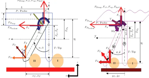
Figure 2 illustrates all the forces that are applied on top of the cantilever. In the nano-manipulation process, the probe is considered as a cylinder shape. The forces, probe and cantilever, as well as the contact force between the particle and the probe or the cantilever and the probe can be observed in Figure 2. In these gures, the forces are shown in two dierent views, y z and x z, where Fy and Fz are horizontal
and vertical components between the cantilever and probe. FT is a contact force between the probe and
the particle.
Figure 2. a) AFM cantilever and probe bending along y-z axes during pushing nano objects [2]. b) AFM cantilever and probe bending along x-z axes during pushing nano objects.
Figure 3. FOB of probe.
Dynamic equations are developed based on the free body diagram (FOB) of a pushing system, includ-ing the AFM cantilever and probe, nanoparticle and substrate. Figure 3 presents the FOB of the probe of the AFM in contact with the particle.
The kinematic equations of the cantilever can be written in the form of Eq. (14):
zp=zafm+ H cos() cos() + (Rp s)
+ (Rt+ Rp t) cos(');
xp = xafm (Rt+ Rp t) sin(') H sin();
yp= yafm (Rt+ Rp t) sin(') H sin(): (14)
In dynamic equations, movement is along X, Y and Z directions and momentum is estimated by balance Eqs. (15)-(18). zp, xp, yp are obtained by
dierentia-tion from equadierentia-tions, then, a nal rate of Fy, Fxand Fz
can be calculated: X
~Fy= m~ay ) FY + (FDtop+ FDbelow) cos
Fy V cos = m
yT + yp
2
; (15) X
~Fx= m~ax) FX+ (FDtop+ FDbelow) sin
Fx V cos = m
xT+ xp
2
; (16) X
~Fz= m~az) FZ+ (FDrag+ Fel+ Fsq+ Fhyd)
Fz V sin V sin = m
zT + zp
2
; (17) X~
Mp= Ip
+ ) M+ FzH sin sin
FYH cos M FxH cos = Ip
+ : (18) Finally, pushing force, FT and , can be calculated
from the following Eqs. (19)-(21):
FXY =
q F2
X+ FY2; (19)
FT =
q F2
XY + FZ2; (20)
= tan 1FY
FZ
: (21)
Friction and normal forces are dened for a semi-static state, based on the probe angle and force, as in the following Eqs. (22):
ft= FTcos ; Ft= FTt:tipsin ;
fs= FTcos FDP; Fs= FTs:subsin : (22)
Ftis the sliding friction force on the probe tip and base
plate, and fsis the friction on the real contact area and
vertical force. So, the frictional model for sliding and rolling is dened in the following equations:
FT > sin FDP+ sAs
scos ; (23)
FT > R FDP:R + rsAs+ rtAt
P(sin + cos ) + rtsin rscos
: (24)
In the above equations, is friction ratio, is shear stability and A is contact area between the particle and base plate. Critical force, FT depends on the particle
moving angle, G, the probe and particle contact angle, frictional constants, contact area, and applied dragging force, on the particle at all times.
4. Simulation of virtual reality environment Dynamic modeling results in understanding the push-ing procedure in real time. Therefore, by modellpush-ing all the forces and dynamics of the particles, nano-particles can be traced momentarily and located at the desired positions [25].
In the nano-manipulation scheme, there are two methods for pushing as follows:
1. The substrate moves the targeted particles;
2. The tip moves and displaces the nano-particle. In this research, it was assumed that the tip moves and displaces the nano-particle. Values that are used in this study are according to the simulation data of Sitti and Tafazoli [26]. Using the same data, Korayem et al., in [27], has compared the ndings of his simulation with previous ndings. In this simulation, a gold particle with Rp = 50 nm has been pushed onto
Table 1. The AFM geometric constants. d
(m) L (m)
W (m)
t (m)
H (m)
Rp (m)
4 225 48 1 12 20
Table 2. Tribological parameters between tip/nano particle and nano particle/substrate.
s d r r
0.8 0.7 80 nm 28 MPa 28 Pa.m Table 3. AFM mechanical properties. E (GPa) v G (GPa) (kg/m3)
169 0.27 66.54 2.330
Figure 4. Virtual reality environment.
velocity. Geometrical and mechanical properties of the RC are summarized in Tables 1, 2 and 3 [26].
The base plate is in the form of a rectangular cube with the following dimensions: (X; Y; Z) = (2000; 2000; 100). The scope of movement for the tip of the AFM probe along X and Y is from 1000 to +1000, and along Z, from 0 to +1000. The primary position for the tip of the probe is (0; 0; h) [28].
Nano-particles with a default radius of Rp =
50 nm are placed on the base plate. The tip of the cantilever probe is shown as a red cone, with a radius of Rtip = 20 nm. The position of the atoms should
be specied by the user who should rst enter the number of the desired atom in the graphical interface of the written software. Then, nal coordinates for manipulation have to be determined, which is set through a slippery band. With the aid of this band, the user can handle X or Y coordinates separately so that the other one remains unchanged. While using the graphical window, the user can simultaneously observe the nal result dynamically.
Figure 4 shows that the desired atom should
Figure 5. Flowchart of virtual reality environment.
be selected for manipulation. After selecting the atom, the destination coordinate has to be inserted for manipulation.
The tip of the AFM probe has a safe height, called hsafe. This height prevents the tip from being
hit or damaged by atoms or other physical obstacles when it moves toward the aimed nano-particle. In this program, it is assumed that one particle which has been chosen by the user is on the base plate, or at least there is no other atom or physical obstacle to the chosen method. An operational owchart of the virtual reality environment is shown in Figure 5.
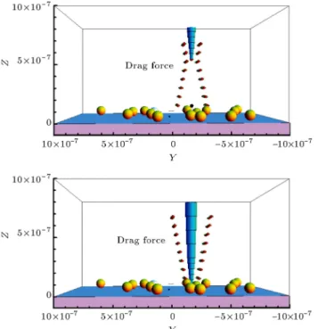
Liquid forces are applied to the tip of the can-tilever. At rst, the solvation force and then pushing forces are applied. In the solvation process, the probe has been surrounded by water molecules. In Figure 6, the drag force on the cantilever is displayed separately. As shown in Figure 7, the electrostatic force is based on the compacting eect and increases by closing the layer.
4.1. Manipulation of nanoparticle
For manipulating nano-particles with the AFM in con-tact mode, the whole operation should be divided into sections, and each section should be studied separately. In Figure 8, dierent stages of pushing the nano-particle are shown and are reported below.
In the nano-manipulation process, the cantilever moves from the origin to the nano-article coordinates. The probe and cantilever move in the air and reach the proper location. Then, the probe and cantilever come
down, get into the water and contact the base. Eective forces are shown in Figure 9. During movement, the probe and cantilever speed is constant.
Liquid forces are applied to the probe and can-tilever. The probe has been surrounded by water molecules. Figure 9 illustrates electrostatic force based on a compacting eect, which is increased gradually.
In the parking stage, the probe contacts the area and the height is increased until a dened height. Figure 10 shows that the nano-particle is pushed and directed to the destination location. The
Figure 6. Applying the F -drag force.
Figure 7. Create and eliminate electrostatic layers and squeeze le eect layer.
liquid forces are applied to the cantilever and the probe.
The cantilever and the probe get back to their original position. The solvation force is applied when the probe is separated from the nano-particle. Then, electrostatic and squeeze lm forces are applied, as shown in Figure 11. The probe is moving away from the
Figure 9. Gathering the water molecules of probe and cantilever and creation of electrostatic layers.
Figure 10. Applying the F-drag force to cantilever horizontally to push the particle.
Figure 11. Applying electrostatic and squeeze le eect to cantilever.
Figure 12. Probe goes away from surface base and eliminates electrostatic and squeeze le eect and hydration forces.
surface base and the electrostatic and squeeze le eect and hydration force were eliminated near the water surface in Figure 12.
5. Results and discussion
Applying liquid forces on virtual reality environments, we can observe the results of the manipulation process
Figure 13. Below and top drag forces.
Figure 14. Electrostatic and hydration forces.
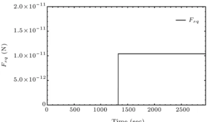
Figure 15. Squeeze eect force.
and see the eects of liquid forces. In Figure 13 the eect of FDtop and FDbelow are shown. Figure 14 also
depicts electrostatic and hydrationn forces. Squeeze and surface forces are shown in Figures 15 and 16, respectively.
Diagrams of FT, Fs and Fr are plotted in
Figure 17. It is shown that the intersection of FT and
FsF diagrams occurs at t = 0:142 s, and a pushing force
of 0.620 N. The intersection of FT and FrF diagrams
occurs at t = 0:162 s, and a pushing force of 0.675 N. So, the nano-particle begins to slide before it rolls.
Rolling force for various submerged lengths of a cantilever in water is simulated. Four points are chosen and the cantilever is considered to be submerged in
Figure 16. Surface force.
Figure 17. The intersection of FT, Fs and Fr diagrams.
Figure 18. The intersection of FT and Fr diagrams for various submerged lengths of cantilever in water.
water up to those points (L = 0, 145, 175 and 200 m). The results are shown in Figure 18 for the rolling force of the nano particle.
Figure 19 illustrates the intersection of the sliding force of nano-particles with FT in an air environment.
The intersection of FT and Fs diagrams occurs at t =
0:134 s and a pushing force of 0.643 N.
In Figure 20, the intersection of the sliding force of nano-particles with FT in a liquid environment is
shown. The intersection of FT and Fsdiagrams occurs
at t = 0:180 s and the pushing force of 0.655 N in the liquid environment.
Figure 19. The intersection of FT, Fs and Frdiagrams in air.
Figure 20. The intersection of FT, Fs and Frdiagrams in liquid environment.
The intersection of FT and Fr diagrams in the
air environment occurs at t = 0:152 s and a pushing force of 0.681 N, while the intersection of FT and Fr
diagrams in a liquid environment occurs at t = 0:203 s and a pushing force of 0.692 N. The results show that sliding and rolling forces in the liquid environment have increased by 2% compared to air.
6. Conclusions
In this paper, forces in a liquid environment were reviewed, and manipulation processes, i.e. pushing a gold nano-particle, were studied by investigating their dynamic behaviour. By use of the nano-particle body diagram and modelling dierent forces, it became possible to determine the exact movement time of the nano-particle, the exact places of the nano-particle and probe tip at any time during pushing. A virtual reality medium for AFM based nano-manipulation in a liquid environment was developed and the manip-ulation process was simulated for nano-particles in a liquid environment. The exact place of the nano-particle was determined through inserting movement information in the VR environment. The eects of dierent submerged lengths of the cantilever have been simulated in this study and also the pushing time for a nano-particle was obtained.
It is concluded that a liquid environment can be used as an appropriate environment for the ma-nipulation process. However, for an accurate nano-manipulation in a liquid environment, more studies and consideration of various intermolecular forces are needed. Results show that sliding forces in a liquid environment have been increased by 2% compared to the air, and the drag force has a smaller eect on the deection of the cantilever than the surface tension [27]. It was obtained that the dierence between the manipulation forces in air and water is not so reasonable, as mentioned in [19]. Liquid envi-ronments are suitable for the prevention of unwanted probe or particle movements, a fact that has been veried by Gauthier [23]. Nano-manipulation in liquid environments can be used for dierent applications in sciences, such as medicine and chemistry, which should be further considered.
References
1. Fotiadis, D., Scheuring, S., Muller, S., Engel, A. and Muller, D.J. \Imaging and manipulation of biological structures with the AFM", J. of Micron, 33, p. 385 (2002).
2. Sitti, M. \Teleoperated 2-d micro/nano manipulation using atomic force microscope", PhD. Dissertation, University of Tokyo, Tokyo, Japan (1999).
3. Savia, M., Koivo, H.N. and Zhou, Q. \Evaluation
of adhesion forces between arbitrary objects", J. of Micromech., 3, pp. 221-238 (2006).
4. Mori, Y. \Eect of surface hydrophobicity on inter-action between particle and at plate at nal stage of wet coating process", J. of Colloids and Surfaces A: Physicochemical and Engineering Aspects, 311, pp. 61-66 (2007).
5. Theander, K., Pugh, R.J. and Rutland, M.W. \Forces and friction between hydrophilic and hydrophobic surfaces: Inuence of oleate species", J. of Colloid Interface Sci., 313(2), pp. 735-46 (2007).
6. Drummond, C. and Israelachvili, J. \Surface forces and wettability", J. of Petroleum Sci. and Eng., 33, pp. 123-133 (2002).
7. Noy, A., Frisbie, C.D., Rosznyai, L.F., Wrighton, M.S. and Lieber, C.M. \Chemical force microscopy: Ex-ploiting chemically modied tips to quantify adhesion, frictionand functional group distributions in molecular assemblies", J. of Am. Chem. Soc., 117, pp. 7943-7951 (1995).
8. Butt, H. \Force measurements with the atomic force microscope: Technique, interpretation and applica-tions", J. of Surface Sci. Reports, 59, pp. 1-152 (2005).
9. Grierson, D.S. and Flater, F. \Accounting for the JKR-DMT transition in adhesion and friction measurements with AFM", J. of Adhesion Sci. Tech., 19, pp. 291-311 (2005).
10. Putman, A.J., Werf, O.W. and Degrooth, G. \Tapping mode atomic force microscopy in liquid", J. of Appl. Phys. Lett., 64, pp. 2454-2456 (1994).
11. Goryacheva, I. and Makhovskaya, Y. \Adhesion eects in contact interaction of solids", J. of Mecanique, 336, pp. 118-125 (2008).
12. Lokar, W.J. and Ducker, W.A. \Approximate pre-diction of adhesionbetween two solids immersed in surfactant solution based on adsorption to anisolated solid", J. of Colloids and Surfaces A: Physicochemical and Engineering Aspects, 332, pp. 256-260 (2008).
13. Liang, Y., Hilal, N., Langston, P. and Starov, V. \Interaction forces between colloidal particles in liquid: Theory and experiment", J. of Advances in Colloid and Interface Science, 135, pp. 151-166 (2007).
14. Luckham, P.F. \Manipulation forces between surfaces: applications in colloid science and biophysics", J. of Advances in Colloid and Interface Science, 111, pp. 29-47 (2004).
15. Carine, L., Chan, Y.C. and Lewis, C. \Measurement of dynamical forces between deformable drops using the AFM", J. of Langmuir, 21, pp. 2912-2922 (2005).
16. Jones, R.E. and Hart, D.P. \Force interactions between substrates and SPM cantilevers immersed in liquids", J. of Tribol., Int., 38, pp. 355-361 (2005).
17. Bonaccurso, E. \Thin liquid lms studied by atomic force microscopy", J. of Current Opinion in Colloid & Interface Science, 13, pp. 107-119 (2007).
18. Chan, D. \Forces between a rigid probe particle and a liquid interface", J. of Colloid and Interface Sci., 236, pp. 141-154 (2000).
19. Resch, R., Lewis, D., Meltzer, S. and Montoya, N. \Manipulation of gold nanoparticles in liquid environ-ments using SFM", J. of Ultramicroscopy, 82, pp. 135-139 (1999).
20. Seantier, B. \Probing supported model and native membranes using AFM", J. of Current Opinion in Colloid & Interface Science, 13, pp. 326-337 (2008).
21. Gauthier, M. \PRONOMIA project: Micro-assembly and modeling of the microworld", Int. Conf. on Intel-ligent Robotics and Systems, San Diego (2007).
22. Dyson, P., Ransing, R.S., Williams, P.M. and Williams, P.R. \Fluid properties at nano/meso scale: A numerical treatment", In Microsystem and Nan-otechnology, Wiley (2008).
23. Korayem, M.H. and Esmaeilzadehha, S. \Virtual real-ity interface for nano-manipulation based on enhanced images", Int. J. of Advanced Manufacturing Technol-ogy, 63, pp. 1153-1166 (2012).
24. Sitti, M. and Tafazzoli, A. \Dynamic behavior and simulation of nanoparticle sliding during nanoprobe-based positioning", ASME Int. Mech. Eng. Congress, pp. 965-972 (2004).
25. Korayem, M.H., Motaghi, A. and Zakeri, M. \Dynamic modeling of submerged nanoparticle pushing based on atomic force microscopy in liquid medium", J. of Nanoparticle Research, 13, pp. 5009-5019 (2011).
26. Korayem, M.H., Esmaeilzadehha, S., Rahmani, N. and Shahkarami, M. \Nano manipulation with rectangular cantilever of atomic force microscope in a virtual reality environment", Digest J. of Nanomaterials and Biostructures, 7, pp. 435-445 (2012).
27. Shen, W. \Adhesion and anti-adhesion of viscous uids
on solid surfaces - A study of ink transfer mechanism in waterless oset printing", J. of Colloid and Interface Science, 318, pp. 348-357 (2007).
28. Best, B., Brockwell, D. and Toca, L. \Force mode atomic force microscopy as a tool for protein folding studies", J. of Analytica Chimica Acta, 479, pp. 87-105 (2003).
Biographies
Soliman Esmaeilzadehha was born in Qazvin, Iran, in 1981. He received BS (Electrical Engineering) and MS (Mechatronics) degrees from Azad University, Iran, in 2003 and 2006, respectively, and is currently a PhD degree candidate at the same institute in the eld of Mechatronics. His research interests include robotic systems, atomic force microscopy dynamics, sensitivity analysis, and nano-technology.
Moharam Habibnejad Korayem was born in Tehran, Iran, in 1961. He received his BS (Hon) and MS degrees in Mechanical Engineering from Amirkabir University of Technology, Tehran, Iran, in 1985 and 1987, respectively and a PhD degree in Mechanical Engineering from the University of Wollongong, Aus-tralia, in 1994. He is currently Professor of Mechanical Engineering at Iran University of Science and Tech-nology, where he has been involved for the last 17 years in teaching and research activities in the area of robotics. His research interests include the dy-namics of elastic mechanical manipulators, trajectory optimization, symbolic modelling, robotic multimedia software, mobile robots, industrial robotics standard, robot vision, soccer robot, and analysis of mechanical manipulators with maximum load carrying capacity. Dr. Habibnejad Korayem has published more than 470 papers in international journals and conferences in these areas.