Sharif University of Technology
Scientia IranicaTransactions A: Civil Engineering www.scientiairanica.com
Geometrical and material nonlinear analysis of
structures under static and dynamic loading based on
quadratic path
I. Mansouri and H. Saari
Department of Civil Engineering, Shahid Bahonar University of Kerman, Kerman, P.O. Box 76169-133, Iran. Received 13 December 2011; received in revised form 9 January 2013; accepted 22 July 2013
KEYWORDS Nonlinear analysis; Large displacement; Quadratic path; Stiness matrix.
Abstract.The Newton-Raphson method, which is based on the Taylor series expansion, and which uses the tangent stiness matrix, has been extensively used to solve nonlinear problems. This traditional method, especially for the large-scale, is time consuming. Consequently, iterative algorithms cannot be eective for analyzing the process. In the incremental-iterative analysis of elastic nonlinear structures, great saving in computation can be achieved if distinction is made between the predictor and corrector phases. This paper shows how a simple assumption can improve the computational eciency of the nonlinear analysis of structures. It is shown that very high computational eciency may be obtained by assuming the pursuit of each Degree Of Freedom (DOF) by a quadratic curve. Through examples, it is demonstrated how this eciency signicantly decreases the computing time of analysis compared with time taken to deploy the Newton-Raphson, modied Newton-Raphson and Conjugate Gradient (CG) methods.
c
2013 Sharif University of Technology. All rights reserved.
1. Introduction
The stability analysis of nonlinear structures includes the solution of large systems of nonlinear algebraic equations for varying values of a control parameter, which is, in most cases, associated with load ampli-tude. In structural mechanics, this problem is usually referred to as that of tracing the equilibrium path of the system. The numerical method constitutes one of the most important aspects in the nonlinear analysis of structures. For deployment of the Newton-Raphson method, the displacement control methods, the per-turbation method, the self-correcting incremental pro-cedure and the incremental stiness propro-cedure, the initial value approach is the commonly used solution for nonlinear problems. Papadrakakis and Gantes [1]
*. Corresponding author. Tel.: +98 9131411509
E-mail addresses: [email protected] (I. Mansouri), [email protected] (H. Saari)
investigated a method to shorten the time taken to deploy Newton methods in nonlinear problems.
For three decades now, nonlinear elastic and inelastic analysis of frame structures has been a subject of considerable research. Kassimali [2] presented a numerical procedure for large deformation analysis of elastic-plastic plane frames. Tabatabaei and Saari [3] studied large strain analysis of planar frames using a normal ow algorithm. Oran and Kassimali [4] investigated the large deformations for the nonlinear analysis of plane frames under static and dynamic loads. Tabatabaei et al. [5] applied the Newton-Raphson iterative algorithm along the normal ow path in nonlinear static analysis of frames. Hsiao and Hou [6] suggested a simple formulation for nonlinear analysis of elastic frames. Wen and Rahimzadeh [7] used a nite element method in nonlinear analysis of elastic frames. Saari et al. [8] introduced a new algorithm for nonlinear analysis of space trusses that can reduce the number of iterations and computing time. Thai and
1596 I. Mansouri and H. Saari/Scientia Iranica, Transactions A: Civil Engineering 20 (2013) 1595{1604
Kim [9] presented the large-deection inelastic analysis of space truss structures, including consideration of both geometric and material non-linearities. Greco et al. [10] proposed a new geometric non-linear formulation for space truss analysis that uses nodal positions rather than nodal displacements. Kwas-niewski [11] suggested the complete equilibrium paths for several Mises trusses. Saari and Mansouri [12] applied a new algorithm for nonlinear analysis of trusses. Pourazarm et al. [13] proposed a numerical algorithm for nonlinear analysis of frames, using the unit displacement method in generating a reduced stiness matrix of the structure. Recently, Saari et al. [14] proposed a fast methodology for elasto-plastic analysis of frames using the homotopy perturbation concept. A method for large deformation elastic-plastic analysis of space frames was undertaken by Abbasnia and Kassimali [15,16], and inelastic post-buckling analysis of truss structures by the dynamic relaxation method has been investigated by Ramesh and Krishnamoorthy [17].
In this study, the eect of large displacements is considered. A quadratic function between forces and deformations is applied in order to enhance speed of convergence and to minimize the cycles required for calculating equilibrium of nodes. Hence, at the beginning of each load step, using force and given deformations, a parabolic curve is passed from three points. The deformations for the next step are ap-proximated using this curve. This process, using the Newton-Raphson method, can be continued until the convergence criterion is satised.
In this paper, two categories of structure are considered: planar frames and space trusses. This approach is designed to emphasize computational load control, rather than to oer improvements (e.g. it ignores the inability of the Newton-Raphson method in passing limit points) to the Newton-Raphson approach per se. However, these problems can be overcome using a form of other methods [8].
2. System equilibrium equation
Consider an arbitrarily framed structure loaded at the nodes only, and let x denote symbolically the corresponding deformed conguration. The equations of equilibrium of the system can be written as:
ff(x)g = fP g; (1) in which ff(x)g is the resultant of the nodal internal forces and fP g represents the external nodal forces. The member force deformation relationships denote that ffg is a highly nonlinear function of fxg.
In the special case of a plane frame, the end forces in the global coordinates are represented by a set of
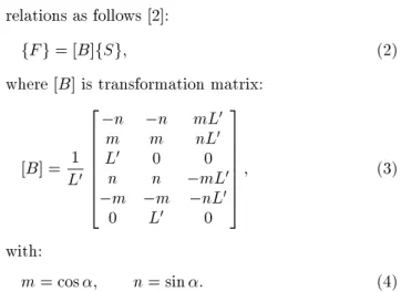
relations as follows [2]:
fF g = [B]fSg; (2) where [B] is transformation matrix:
[B] = 1 L0
2 6 6 6 6 6 6 4
n n mL0
m m nL0
L0 0 0
n n mL0
m m nL0
0 L0 0
3 7 7 7 7 7 7 5
; (3)
with:
m = cos ; n = sin : (4) In Eqs. (3) and (4), L0 and refer to the length and
orientation, respectively, of the chord of the element in its deformed congurations, as shown in Figure 1. A procedure for obtaining L0, m, n has been published
in [2] and is not repeated herein. In Eq. (2):
fSg = 8 < :
M1
M2
Q 9 =
; ; (5)
denote the local member end forces as shown in Figure 2 [2].
Figure 1. Member forces and deformations in global coordinates.
Figure 2. Member forces and deformations in local coordinates.
Figure 3. Initial and current conguration for typical truss member.
For a space truss element (Figure 3) the relation-ship between the end forces of the member in global and local coordinates is [18]:
fF g = fBgQ: (6)
Here, Q is the local internal axial force of the truss member, and fBg is the transformation matrix:
fBg = 8 > > > > > > < > > > > > > :
l m
n l m
n 9 > > > > > > = > > > > > > ;
; (7)
in which l, m and n are the cosine directors of the element axis.
A detailed discussion for obtaining l, m, n and Q is provided in [18].
2.1. Material nonlinearity analysis 2.1.1. Truss element
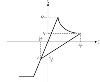
The accuracy of the inelastic response of structures depends on the accuracy of the member's load-displacement relationship used in the analysis. A num-ber of models have been introduced in the literature to predict the nonlinear behavior of space trusses. In this study, a stress-strain relationship proposed by Hill et al. [19] is adopted to predict the inelastic post-buckling behavior of trusses. The force-strain curve (Q u=L) is assumed applicable for steel material both in tension and compression states and is shown in Figure 4.
The curve can be expressed by the following relations:
Figure 4. Proposed solution scheme.
- For tensile members:
Q = (
A:E
L u for juj < uy
A:Fy for juj uy (8)
where L is length of element, A is cross-sectional area, E is modulus of elasticity, Fy denotes yield
stress and uy is Fy:L=E.
- For compressive members:
Q = 8 > > > < > > > :
A:E L u
for u < ucr
Ql+ (Qcr Ql):e[ (X1+X2
p
u0=L)u0=L]
for u ucr
(9)
Here:
Qcr= 2EI=L2:
I is weak axis moment of inertia. Ql is the
asymptotic lower stress limit and is dened as Ql = r:Qcr. The corresponding critical buckling
displacement is ucr = Qcr:L=(A:E), while u0 is
dened as u0 = u ucr. Parameters X1 and X2
are constants, depending on the slenderness ratio of the compressive members.
It should be noted that when a member is in a compression state and u ucr, the tangent modulus,
Et, has to be used instead of E. The tangent modulus
is obtained as:
Et= A1(Qcr Ql):e[ (X1+X2
p
u0=L)u0=L]
:(X1+32X2
p
u0=L): (10)
It can be seen that if the loading path reaches point A, the member behavior follows the relations in Eq. (8).
1598 I. Mansouri and H. Saari/Scientia Iranica, Transactions A: Civil Engineering 20 (2013) 1595{1604
2.1.2. Frame element
A-perfectly plastic material associated with the plastic hinge concept is used in this study to consider the material non-linearity eect. In an elastic perfectly-plastic material, the eects of strain hardening are disregarded. It further implies that once the yield moment Mpcis reached, the material yields and cannot
withstand further stress.
It is of note that yield moment is commonly dened by a yield criterion. A variety of yield cri-teria denitions have been introduced in structural engineering. In this paper, the AISC-LRFD 2005 [20] criterion, considering bending moment and axial force interaction, is used for steel elements. This criterion and its corresponding descriptive relation are shown below: 8 > > > > > > > < > > > > > > > : jQj 2Qc +
Mcx
Mpcx +
Mcy
Mpcy
= 1 for jQjQc < 0:2
jQj Qc +
8 9
Mcx
Mpcx +
Mcy
Mpcy
= 1 for jQjQc 0:2;
(11)
in which Mc = bZFy, Mpc represents reduced
plas-tic moment capacity in the presence of axial force (Qc = cQn); where b and c are bending and axial
resistance factors, respectively; Fy denotes yield stress,
and Z stands for plastic modulus.
3. Nonlinear dynamic analysis
The method of analysis used in the present study is briey reviewed herein. Detailed derivation of the method can be found in [18].
3.1. Equations of motion
Among time integration methods, the Newmark method is the most extensively use in nonlinear dy-namic analysis of structures because of its accuracy and stability. Therefore, the Newmark method is adopted here to solve the nonlinear equation of motions of struc-tures. The Newton-Raphson iteration is performed at each time step to dissipate any unbalanced forces.
The incremental equation of motion of a structure can be expressed as:
[M] fxg + [C] f _xg + [] fxg = fP g ; (12) in which fP g indicates load increments, fxg, f _xg and fxg represent increments of accelerations, ve-locities and displacements, respectively, and [M], [C] and [] are the mass, damping, and tangent stiness matrices, respectively.
With the adoption of the average acceleration method of the Newmark family ( = 0:25; = 0:5),
incremental acceleration and velocity at the rst itera-tion of each time step can be expressed as:
fxg =t42fxg t4 f _xig 2 fxig ; (13)
f _xg =t2 fxg 2 fxig : (14)
Substituting Eqs. (13) and (14) into Eq. (12), the incremental displacement can be given by:
[] fxg = P ; (15) in which [] and f P g are the eective stiness matrix and incrementally eective load vector, respectively, given by:
[] = t42[M] + t2 [C] + []; (16)
P = fP g + 4
t[M] + 2[C]
f _xig
+ 2[M] fxig : (17)
At the rst iteration of each time step, the total displacement, velocity, and acceleration at time t + t is updated according to the incremental displacement vector fxg as:
fxi+1g = fxig + fxg ; (18)
f _xi+1g = f _xig + t2 fxg ; (19)
fxi+1g = fxig t4 f _xig + t42fxg : (20)
For the second and subsequent iterations of each time step, the structural system is solved, subject to the eect of the unbalanced load fQg, as:
[] fxg = fQg ; (21) where the unbalanced load fQg is determined based on the total external load fP g, inertial force, damping force, and updated internal force ffg, as follows:
fQg = fPi+1g [M] fxi+1g [C] f _xi+1g ffg:
(22) When the convergence criterion is satised, the struc-tural response is updated for the next time step as:
xk+1 =xk + fxg ; (23)
fxi+1g = fxig +xk+1 ; (24)
f _xi+1g = f _xig + t2 xk+1 ; (25)
fxi+1g = f _xig t4 f _xig + t42xk+1 : (26)
The details of the method for the application of the Newmark method and the Newton-Raphson iteration are as follows [21]:
Step 1. Predictor phase:
I. Form the eective stiness matrix [];
II. Form the eective force vector f P g;
III. Solve for fxg using Eq. (15).
Step 2. Corrector phase (force recovery):
I. Update structural conguration and motion;
II. Update the member force. Step 3. Convergence:
I. Compute the unbalanced load;
II. Check convergence: If the convergence exists, update structural conguration and motion at time t + t and go to the next time step. Otherwise, apply the unbalanced load on the structure system and go to Step 1.
4. Nonlinear analysis algorithms
In this section, three methods and a new approach for nonlinear analysis of structures are described.
4.1. Newton-Raphson method
The Newton-Raphson method oers one of the popular iterative methods for solving nonlinear equations. Via this method, an approximate solution is estimated, and then an unknown value is added as a corrector value to improve the initial solution. Using Taylor series, the system of nonlinear equations can be changed to linear form, and by solving this linear system, it is possible to achieve the corrector value and an improved solution. This process is continued until an acceptable approximation is obtained [22].
4.2. Modied Newton-Raphson method
For the conventional Newton-Raphson method, the tangent stiness is reformed every iteration and, for the modied Newton-Raphson method, it is only reformed in the rst iteration. The conventional Newton-Raphson method normally takes fewer iterations for convergence, but the computing time for each iteration in the modied Newton-Raphson method is shorter. This is signicant because the solution and formation of the tangent stiness matrix is a time-consuming process.
4.3. Conjugate Gradient (CG) method
The problem of solving nonlinear equations by the CG method may be viewed as a problem of minimizing a twice continuously dierentiable nonquadratic func-tion. Papadrakakis and Gantes [1] presented some procedures to truncate the Newton-Raphson method. The truncated Newton method is dened by the pre-conditioned CG to compute the search direction, and
the details of this method can be found in the afore-mentioned reference.
4.4. Quadratic path as an initial guess
The incremental-iterative methods may be the most popular solution methods used in nonlinear analysis. In the linear incremental method, load-deection behavior is approximated as piecewise linear, which produces unbalanced forces between externally applied loads and internal nodal loads. The presence of these unbalanced forces violates the equilibrium of the structure. If the unbalanced forces are not eliminated or reduced to a certain acceptable level, the calculated load-displacement relation will drift away from the true behavior of the structure. An iteration procedure may be used to eliminate these unbalanced forces in each incremental step. It is, therefore, necessary to use an incremental-iterative solution method to obtain more accurate results.
In the incremental-iterative analysis of elastic nonlinear structures, great saving in computation can be achieved if distinction is made between the predictor and corrector phases. The predictor relates to the solution of structural displacements for given load increments, which aects only the number of iterations. For the sake of the iterations, the equations used in the predictor need not be exact, but should be accurate enough not to mislead the direction of iterations. To approximate a curve, one naturally thinks of using a series of segments. The smaller the size for these segments, the closer the approximation will be, but the heavier the computational eort required.
In this paper, it is assumed that each DOF of displacements follows from a quadratic function, independently. As an initial approximation, this as-sumption is used at the beginning of load stepping. Therefore, there is no need to construct the tangent stiness matrix at the beginning of each load step and so, the analytical computing time will be re-duced. Furthermore, a more accurate approximation may be obtained by using a quadratic function as a rapidly converging iterative method. In the proposed technique, and like the modied Newton-Raphson method, the tangent stiness is reformed at only the rst iteration. The procedure can be summarized as follows.
The total external nodal load on a structure, at each loading step fPig, can be calculated by production
of a total load ratio at each step, i, and a given
ref-erence load fPrefg (in the case of proportional loading,
the total external load vector can be obtained by simple scaling of a reference load vector) is applied through a series of load increments fP g. Mathematically, this is stated as:
fPig = ifPrefg =
X
1600 I. Mansouri and H. Saari/Scientia Iranica, Transactions A: Civil Engineering 20 (2013) 1595{1604
The approximate displacements vector at the (i + 1)th step, fdi+1g, can be estimated as (i 3):
fdi+1g = fdig; (28)
where:
=d
i+1 kj
di
j : (29)
Here, di
j is a scalar which represents the displacement
of the jth DOF of the structures at converged step i, and di+1
kj is the estimated displacement of that DOF
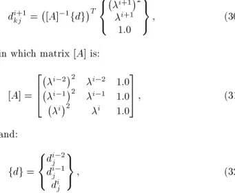
at the (i + 1)th step and kth iteration, which can be calculated as follows:
di+1
kj = [A] 1fdg
T
8 < :
i+12
i+1
1:0 9 =
;; (30)
in which matrix [A] is:
[A] = 2 6 4
i 22 i 2 1:0
i 12 i 1 1:0
i2 i 1:0
3 7
5 ; (31)
and:
fdg = 8 < :
di 2 j
di 1 j
di j
9 =
; ; (32)
and the superscript T represents transposition. A program implementing the two-point algorithm has been written in MATLAB and representative results are provided. Material nonlinearity is not presently included in the algorithm. The graphical representation of this process is shown in Figure 5.
Figure 5. Proposed solution scheme.
5. Numerical examples
Four numerical examples were solved in a microcom-puter environment so that the eciency of the proposed procedure used together with the Newton-Raphson and modied Newton-Raphson methods in nonlinear behavior of planar frames could be compared. The computer program was developed based on the proce-dure described in this paper. All examples have been solved with a 32 bit Pentium 2.00 GHz processor (2 CPUs). For the solution of nonlinear equations, a new iterative method is adopted and the iterative process will stop when the convergence criteria are satised. The convergence criterion, based on displacement, used herein, is given by:
v u u u t
P
i (xi) 2
P
i (xi)
2 e; (33)
where e is the error tolerance. All the numerical examples presented here use a tolerance of 10 3. It
should be noted that the computing time is for twenty analyses in all examples.
5.1. Example 1
Figure 6 shows a two-bay, six-storey frame subjected to distributed gravity and lateral loads with its associated
Figure 7. Load-displacement curve for two-bay six-storey frame.
data [22]. The elastic modulus for all members E is 20500 kN/cm2. It is assumed that P = 102:2 kN
and = 0:02. In this example dj is 61. The
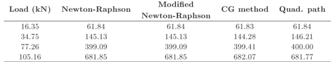
developed method here is applied to plane frames in which elastic-perfectly plastic behavior is assumed for structural material, while conventional plastic hinges of zero length are used to model the plasticity eect. The path of load-deformation curves is shown in Figure 7. To compare the performance of the proposed method, the results of analyses are summarized in Tables 1 and 2.
5.2. Example 2
The star truss, shown in Figure 8, having 24 elements and 13 nodes with pin supports at the outer nodes, is taken from [18], which provides a good opportunity to evaluate the eciency of the method discussed here. The cross-section area, modulus of elasticity and mass per unit length for all members are A = 6:45 cm2,
E = 6:9 MPa and m = 690 N.S2/cm2, respectively. A
Figure 8. Star dome truss, dimensions are given in cm.
Figure 9. Dynamic forcing function (td= 0:01 Sec).
dynamic forcing function considered for this structure is shown in Figure 9.
Figure 10 shows the load-displacement curve ob-tained by applying the method developed during the present study.
Table 1. Corresponding displacements (mm) obtained by current and other methods in Example 1. Load (kN) Newton-Raphson Modied
Newton-Raphson CG method Quad. path
16.35 61.84 61.84 61.83 61.84
34.75 145.13 145.13 144.28 146.21
77.26 399.09 399.09 399.41 400.00
105.16 681.85 681.85 682.07 681.77
Table 2. Computing time of 20 times analysis for two-bay six-storey frame (sec).
Newton-Raphson Modied
Newton-Raphson CG method Quad. path
1602 I. Mansouri and H. Saari/Scientia Iranica, Transactions A: Civil Engineering 20 (2013) 1595{1604
Figure 10. Load-deection curve for Example 2.
The results show that the computing time used in deploying the classic Newton-Raphson approach is more than that used by applying our method. The results are presented in Tables 3 and 4.
5.3. Example 3
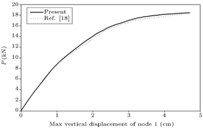
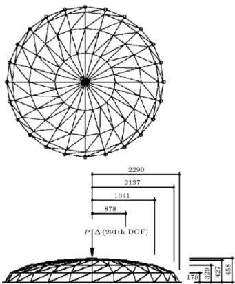
The circular dome truss taken from Thai and Kim [9] is shown in Figure 11. This structure is subjected to a vertical load at the apex and has 168 elements with 73 nodes, with a total of 147 degrees-of-freedom. The out-of-plane motion has been constrained with pin supports added to each end of the truss. The cross-sectional area, A, is equal to 50.431 cm2 for all the
members. Also, the following parameters are assumed for this dome: E = 2:04 104 kN/cm2, P = 820 kN
and = 0:024.
For this truss, dj can be given as 117. The
proposed algorithm is applied to two cases of elastic and
Figure 11. Circular dome truss; dimensions are given in cm.
Inelastic Post-Buckling (IPB) analyses of this truss. Figure 12 shows the variation of vertical displacement with the load P . Tables 5 and 6 document the performance of the methods.
5.4. Example 4
This truss, shown in Figure 13, with 264 elements and 97 nodes, with pin supports at the outer nodes, gives a possibility of comparison with results in the
Table 3. Corresponding displacements (cm) obtained by current and other methods in Example 2. Load (kN) Newton-Raphson Modied
Newton-Raphson CG method Quad. path
3.55 2.28 2.28 2.30 2.28
10.67 8.44 8.45 8.43 8.45
15.58 19.60 19.59 19.62 19.61
Table 4. Computing time of 20 times analysis for Example 2 (sec).
Newton-Raphson Modied
Newton-Raphson CG method Quad. path
44.03 26.48 19.37 15.92
Table 5. Corresponding displacements (cm) obtained by current and other methods in Example 3. Load (kN) Newton-Raphson Modied
Newton-Raphson CG method Quad. path
149.46 0.49 0.49 0.49 0.49
400.0 1.42 1.42 1.40 1.41
600.0 2.48 2.48 2.47 2.47
Table 6. Computing time of 20 times analysis for circular dome truss (sec).
Newton-Raphson Modied
Newton-Raphson CG method Quad. path
93.71 71.25 37.44 24.07
Table 7. Corresponding displacements (cm) obtained by current and other methods in Example 4. Load (kN) Newton-Raphson Modied
Newton-Raphson CG method Quad. path
5.46 0.89 0.89 0.90 0.89
17.65 3.41 3.42 3.42 3.43
27.11 7.96 7.96 7.97 7.93
Figure 12. Load-displacement curve for circular dome truss.
Figure 13. Schewdeler's dome truss; dimensions are given in cm.
Table 8. Computing time of 20 times analysis for Schewdeler's truss (sec).
Newton-Raphson
Modied Newton-Raphson
CG method Quad. path
121.29 87.35 54.28 26.34
Figure 14. Load-displacement curve for Schewdeler's dome truss.
literature [10]. The axial stiness for all members is EA = 640 103 kN. The external loading was
equip-ment loading, which consists of P = 30 kN at the crown node and = 0:033. For this structure, dj is 291.
The load-displacement curve for this structure is shown in Figure 14. Tables 7 and 8 documents the comparison between results obtained using the Newton-Raphson and the newly introduced method.
6. Conclusions
The implementation of a simple and eective method has been discussed. The use of the quadratic function between load and deections as the initial guess at the beginning of each load step allows easy implementation of large displacement analysis. In other words, in the proposed technique, the quadratic curve plays the predictor role. The deformations for the next step are approximated using this curve. In this method, there is
1604 I. Mansouri and H. Saari/Scientia Iranica, Transactions A: Civil Engineering 20 (2013) 1595{1604
no need to construct the tangent stiness matrix at the beginning of each load step and, so, the computing time of analysis will be reduced. A numerical procedure was written into a computer program. The results reveal that deployment of the quadratic path oers high ac-curacy and can be an ecient technique for geometrical and material nonlinearity analysis of structures which are otherwise inconveniently time-consuming.
References
1. Papadrakakis, M. and Gantes, C.J. \Truncated New-ton methods for nonlinear nite element analysis", Comput. Struct., 30(3), pp. 705-714 (1988).
2. Kassimali, A. \Large deformation analysis of elastic-plastic frames", J. Struct. Eng., ASCE., 109(8), pp. 1869-1886 (1983).
3. Tabatabaei, R. and Saari, H. \Large strain analysis of two-dimensional frames by the normal ow algorithm", Struct. Eng. Mech., 36(5), pp. 529-544 (2010).
4. Oran, C. and Kassimali, A. \Large deformations of framed structures under static and dynamic loads", Comput. Struct., 6(6), pp. 539-547 (1976).
5. Tabatabaei, R., Saari, H. and Fadaee, M.J. \Appli-cation of normal ow algorithm in modal adaptive pushover analysis", J. Constr. Steel Res., 65(1), pp. 89-96 (2009).
6. Hsiao, K.M. and Hou, F.Y. \Nonlinear nite element analysis of elastic frames", Comput. Struct., 26(4), pp. 693-701 (1987).
7. Wen, R.K. and Rahimzadeh, J. \Nonlinear elastic frame analysis by nite element", J. Struct. Eng., ASCE., 109(8), pp. 1952-1971 (1983).
8. Saari, H., Fadaee, M.J. and Tabatabaei, R. \Non-linear analysis of space trusses using modied normal ow algorithm", J. Struct. Eng., ASCE., 134(6), pp. 998-1005 (2008).
9. Thai, H. and Kim, S. \Large deection inelastic anal-ysis of space trusses using generalized displacement control method", J. Constr. Steel Res., 65(10-11), pp. 1987-1994 (2009).
10. Greco, M., Gesualdo, F.A.R., Venturini, W.S. and Coda, H.B. \Nonlinear positional formulation for space truss analysis", Finite Elem. Anal. Des., 42(12), pp. 1079-1086 (2006).
11. Kwasniewski, L. \Complete equilibrium paths for Mises trusses", Int. J. Non-Linear Mech., 44(1), pp. 19-26 (2009).
12. Saari, H. and Mansouri, I. \Non-linear analysis of structures using two-point method", Int. J. Non-Linear Mech., 46(6), pp. 834-840 (2011).
13. Pourazarm, B., Vahdani, S. and Farjoodi, J. \Reduced stiness method for nonlinear analysis of structural frames", Sci. Iran., 18(2), pp. 181-189 (2011).
14. Saari, H., Mansouri, I., Bagheripour, M.H. and Dehghani, H. \Elasto-plastic analysis of steel plane frames using homotopy perturbation method", J. Con-str. Steel Res., 70, pp. 350-357 (2012).
15. Abbasnia R. and Kassimali A. \Large deformation elastic-plastic analysis of space frames ", J. Constr. Steel Res., 35(3), pp. 275-290 (1995).
16. Kassimali, A. and Abbasnia, R.\ Large deformation analysis of elastic space frames", J. Struct. Eng., ASCE, 117(7), pp. 2069-2087 (1991).
17. Ramesh, G. and Krishnamoorthy, C.S. \Inelastic post-buckling analysis of truss structures by dynamic relax-ation method", Int. J. Numer. Methods Eng., 37(21), pp. 3633-3657 (1994).
18. Kassimali, A. and Bidhendi, E. \Stability of trusses under dynamic loads", Comput. Struct., 29(3), pp. 381-392 (1988).
19. Hill, C.D., Blandford, G.E. and Wang, S.T. \Post-buckling analysis of steel space trusses", ASCE J. Struct. Eng., 115, pp. 900-919 (1989).
20. Load and Resistance Factor Design (LRFD) Spec-ication for Structural Steel Buildings, 2nd Edn., Chicago, American Institute of Steel Construction (AISC) (2005).
21. Thai, H.T. \Practical nonlinear inelastic static and dynamic analysis of space steel structures", Republic of Korea: Sejong University, Doctoral Dissertation (2009).
22. Chan, S.L. and Chui, P.P.T., Non-linear Static and Cyclic Analysis of Steel Frames with Semi-Rigid Con-nections, Elsevier Science, The Netherlands (2000).
Biographies
Iman Mansouri received his MS degree in Structural Engineering, in 2009, from Shahid Bahonar University of Kerman, Iran, where he is currently pursuing a PhD degree. His main research interests include: nonlinear solution methods, development of inelastic material and member models for nonlinear structural analysis, steel beam-to-column connections behavior and performance-based design. He is also co-author of several publications.
Hamed Saari received his BS degree from Shahid Bahonar University of Kerman, Iran, and MS and PhD degrees from the Science and Technology University of Iran, Tehran, Iran. He is currently Professor of Structural Engineering in the Department of Civil Engineering at Shahid Bahonar University of Kerman, Iran. His research interests include: structural stabil-ity, nonlinear structural analysis, steel structures and rehabilitation of structures.