Sharif University of Technology
Scientia IranicaTransactions B: Mechanical Engineering www.scientiairanica.com
Numerical study of joint behaviour for top-seat ange
cleat connection in cold-formed steel structures
Y.H. Lee
a;, C.S. Tan
a, S. Mohammad
a, J.B.P. Lim
band R. Johnston
c a. Faculty of Civil Engineering, Universiti Teknologi Malaysia, 81310 Johor Bahru, Johor, Malaysia. b. Department of Civil and Environmental Engineering, The University of Auckland, New Zealand. c. School of Planning, Architecture and Civil Engineering, Queen's University Belfast, United Kingdom. Received 22 May 2014; received in revised form 12 November 2014; accepted 5 January 2015KEYWORDS Bolted connection; Joint behaviour; Cold-formed steel; Light steel frame; Stiness;
Strength.
Abstract. The use of cold-formed steel for primary load bearing members in low and medium rise buildings has become an increasingly popular form of construction. The design of connections between these members is crucial to the overall structural integrity of such buildings. However, for beam-to-column joint design, recent codes of practice show ambiguity in the mechanical behaviour. Further research is required to investigate the strength, stiness and ductility prediction of such connections. This paper addresses these concerns by proposing simplied formulas for the moment-rotation behaviour of light steel frames with bolted top-seat ange cleat joints. A nite element study is presented which is validated against laboratory experimental tests on cold-formed steel arrangements. The validated model is used within a parametrical study to investigate several additional geometrical parameters that are not included in the experimental works. An exponential equation has been proposed for large deformation of top-seat ange cleat joint under monotonic vertical load. The predictions using the equations are compared to the design codes (BS EN1993-1-8) and experimental data. From the comparison, the proposed equation can improve the BS EN1993-1-8 prediction from 168.08% dierence, compared to experimental results, to 7.09% dierence. The new proposed model gives a safe design for top-seat ange cleat joint in cold-formed steel light frame construction. © 2015 Sharif University of Technology. All rights reserved.
1. Introduction
Light steel frame system utilising cold-formed steel sections has become a popular form of construction in recent years. This is due to the economic and sustainability benets. The cold-formed steel members can satisfy load bearing requirements, yet they are light weight as compared to hot-rolled steel. This saving in material weight and ease of construction means this form of construction is able to compete with traditional
*. Corresponding author.
E-mail addresses: [email protected] (Y.H. Lee); [email protected] (C.S. Tan); [email protected] (S. Mohammad); [email protected] (J.B.P. Lim); [email protected] (R. Johnston)
masonry and timber construction. Other benets of cold-formed steel construction include durability, quality and speed of construction, design exibility and cost savings. In addition, it is a sustainable form of construction, requiring smaller manufacturing plant, machinery and material resources. Cold-formed steel is also a recyclable material which can be reused or recycled after demolition of an obsolete building. Light steel frames are often used for medium-rise or low-rise residential buildings that have modest span. The frames of cold-formed steel buildings are suitable for o-site constructions, leading to reduced labour costs and time for site construction. Cold-formed steel structures also have simple bolts connections, compared to hot-rolled steel connections which can require larger connection costs due to welding. This
is an important factor when considering the benets of cold-formed steel structures, as the cost of fabricating connections can account for approximately 50% of the total costs in steelwork construction [1].
Most of the codes and standards use the single fastener capacity method in the prediction of cold-formed steel joint structural behaviour. The compo-nent method in the Eurocodes considers the adjacent member capacity. This is more accurate for cold-formed steel design since failure may occur on the member (through buckling), rather than failure of the connection itself - this is due to the thin-walled nature of cold-formed steel sections. Therefore, the Eurocode is used in this investigation for joint design. For beam-to-column connections, there are three common types of connections that are suitable, namely, welded connection, bolted connection and screw connection. However, according to Wong (2002) [2], cold-formed steel sections with thickness less than 3.2 mm are not suitable for welding as the heat from the welding process will burn through the section. There is also a limitation on screw connections, where the thickness of thicker part should not exceed 12.7 mm (0.5 inch) [3] and the diculty increases with higher steel grade of cold-formed steel. This is due to practical limitations and screw tapping characteristics. Bolted connection is another alternative for cold-formed steel beam-to-column connections in light steel frame. In BS EN1993 Part 1.8 (hereby addressed as BS EN1993-1-8) [4], there are two typical bolted joints that have been codied: end-plate connection and top-seat angle connection. Since the end-plate connection also needs welding process, it is therefore advisable to use top-seat angle connections in light steel frame design.
The top-seat ange cleat connection has a simple joint conguration and requires no welding, recom-mended by BS EN1993-1-8 [4]. The behaviour of top-seat ange cleat connections using hot-rolled steel has been investigated by a number of researchers [5-10] in which they have classied it as a semi-rigid joint. For Eurocode design specications, the eective width method is applied to distinguish between compact hot-rolled steel and slender cold-formed steel when consid-ering instability problems of large deection analysis. However, for the component method used in connection design, the Eurocodes do not provide the joint analysis for large deection that is experienced by cold-formed steel structures in light steel frame.
For hot-rolled steel sections, several mathematical models have been developed to idealise the moment-rotation curve of several structural joints [11-22]. These are outlined in more details. The rst model was developed for the prediction of the initial rotational stiness for riveted connections [11]. An improved bilinear model [12-14] was proposed to represent both the initial rotational stiness as well as the plastic
behaviour. A multi-linear mathematical model was preached by Razzaq to further increase the accuracy in the moment-rotation behaviour [15].
Frye and Morris [16] developed a mathematical model with polynomial equations, based on Sommer's equation [17] that used the least square method for determining the polynomial constant for top-seat ange cleat connections [16]. Kishi and Chen [18] rened Lui and Chen's model [14] to show critical changes in the rotational stiness of the moment-rotational curve. Kishi and Chen adopted Heaviside's step function for the exponential model which solves the full range of relative rotation with secant connection stiness in a second order analysis. A four-parameter exponential mathematical model was proposed in [19-22]. Kishi and Chen presented two-parameter [20], three-parameter [21] and power models [22].
Existing studies for the moment-rotation be-haviour of bolted moment connections under mono-tonic loading are therefore well-established for hot-rolled steel. Despite this, there is little information available for the design light steel frames with bolted top-seat ange cleat connections. Some work on cold-formed steel top seat ange cleat connections was presented by Tan [23] in which a series of experimental studies were performed. However, a comprehensive mathematical equation that accommodates the large deection analysis to represent the moment-rotation behaviour of such connections has not yet been devel-oped. Since the mechanical behaviour of cold-formed steel varies signicantly from that of hot-rolled steel, adapting hot-rolled connection design may not be safe. This paper addresses the mentioned concerns and presents the design of bolted top-seat ange cleat connections in light steel frame. It includes a study to investigate parameters that inuence the moment-rotation behaviour of cold-formed steel top-seat ange cleat connections. The investigated parameters include the elastic rotational stiness, ke, plastic rotational
stiness, kp, and plastic moment resistance of the
connection, Mpl. An empirical model is proposed which
represents the large deformation moment-rotation be-haviour for top-seat ange cleat connections. The inuences of the thickness of the ange cleat and column ange, as well as the depth of the beam were also investigated. The elastic rotational stiness is represented by an equation developed on the least squares method using nite element models, which was then applied to the proposed moment-rotation curve approximation.
2. Investigation models for bolted joint
There are three developed investigation models, namely, BS EN1993-1-8, experimental and nite ele-ment models. The unit for rotational stiness and
mo-ment resistance are kNm/Rad and kNm, respectively, throughout the study.
2.1. BS EN1993-1-8 model
The top-seat ange cleat connection has been codied in BS EN1993-1-8. The design resistance of the joint is calculated with component method. BS EN1993-1-8 has provided the procedures to obtain the compo-nent resistances for design purpose. The compocompo-nent resistance includes bolt tension resistance, bending resistance of ange cleat, bending resistance of column ange, transverse tension resistance of column web, compression resistance of beam and column ange, compression resistance of beam and column web, shear resistance of column web panel and shear resistance of bolts. The investigation has been discussed in [24-26]. The moment-rotation curve is plotted with the calculated joint moment resistance. For conservative design, Eurocode has limited the model behaviours as elasto-plastic with no plastic rotational stiness and fails at the lowest stiness component. This character-istic is suitable for hot-rolled steel. The calculation is based on the yield line pattern for component failure mode and the joint resistance. There are two identied yield line patterns: circular and non-circular patterns. According to BS EN1993-1-8, there are three structural properties in the moment-rotation behaviour, namely moment resistance (strength), rotational stiness and rotation capacity (ductility), which are discussed in the following section.
2.2. Experimental investigation
Three tests were carried out in the Laboratory of Struc-tures and Materials, Universiti Teknologi Malaysia. Figure 1 shows details of the experimental test setup. The thickness of the ange cleat used depended on the
Figure 1. Experimental set up of full-scale isolated joint test.
beam depth. The beam depths used were: 150 mm, 200 mm, and 250 mm. These beams are referred to as DC150, DC200 and DC250, respectively. For all beam sizes, 6 mm ange cleats were used as connectors. Back-to-back channel sections were used for the beams and columns. Further details of the experimental studies are found in [23,25,26]. The experimental results were applied for the model validation of de-veloped numerical models and compared to the newly developed formulation at later stage.
With reference to Yu et al. (2005) [27], the same test conguration was set for the experimental study. The data transducer was placed at 1000 mm from column surface for taking the deection of beam bending parallel to loading point. Inclinometers were located, as shown in Figure 1, for the record of the rotations of beam and column.
2.3. Numerical investigation 2.3.1. Verication and validation
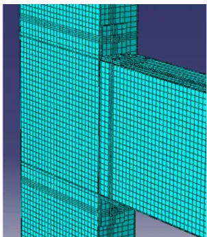
From the process of verication and validation, the ex-pected outcome is the quantied level of agreement be-tween experimental results and model prediction [28]. The factor of high accuracy of the developed predictive model is the driven force to execute the verication and validation process. The nite element program ABAQUS version 6.9 was used to model the top-seat ange cleat joint. The details of modelling technique on cold-formed steel with top-seat ange cleat connections have been proposed [24-26]. Figure 2 shows the details of the nite element model.
The important activity of calculation verica-tion is performing grid or time convergence study by successively rening the mesh or time step until a sucient level accuracy is obtained [28]. The results
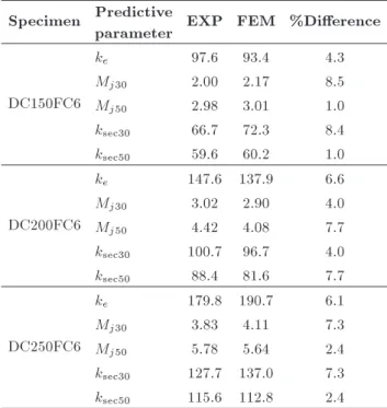
Table 1. Summary of validation results. Specimen Predictive
parameter EXP FEM %Dierence
DC150FC6
ke 97.6 93.4 4.3
Mj30 2.00 2.17 8.5
Mj50 2.98 3.01 1.0
ksec30 66.7 72.3 8.4
ksec50 59.6 60.2 1.0
DC200FC6
ke 147.6 137.9 6.6
Mj30 3.02 2.90 4.0
Mj50 4.42 4.08 7.7
ksec30 100.7 96.7 4.0
ksec50 88.4 81.6 7.7
DC250FC6
ke 179.8 190.7 6.1
Mj30 3.83 4.11 7.3
Mj50 5.78 5.64 2.4
ksec30 127.7 137.0 7.3
ksec50 115.6 112.8 2.4
were documented in [24]. High von Mises stress was found at the component with low stiness. Meshing, geometrical properties and boundary conditions were checked to eliminate the errors. Therefore, BS EN1993-1-8 achieved good agreement with numerical model for model verication.
The assessment of model validation determines the degree of accuracy in representing the real be-haviour from the perspective of the intended uses of the model [24]. For model validation, the results were summarized in Table 1 and compared to the experimental data. Comparison was made on elas-tic rotational stiness, secant rotational stiness and resistance at desired rotations. In order to fulll the minimum requirement of connection ductility, the rotation capacity of ductile connection has been ranged between 0.02 Rad to 0.03 Rad rotations [29]. Cold-formed steel exhibits large plasticity performance and the connection have the possibility to fail at large deection that exceeds 0.05 Rad. The limitation has been made at 0.05 Rad to avoid excessive deformation of the connected members for exible connection
speci-mens [30]. Therefore, the rotation limitations are set at 0.03 Rad and 0.05 Rad. The secant rotational stiness and strength comparisons are made on the point of 0.03 Rad and 0.05 Rad rotations, respectively.
Statistical T-test analysis is performed to cor-relate the developed nite element models with ex-perimental data. The analysis covers 99% level of condence. There are two evidences that the null hypothesis should not be rejected at the 99% condence interval of the dierence, as shown in Table 2. The lower boundary of condence level is below zero, 4:12349, and the upper boundary of the condence level is a positive number, 4.28615. Hence, there is a possibility that the population means of the dierences is zero and it fails to reject the null hypothesis. In addition, the Sig (2-tailed) value is 0.955, and it is greater than 0.05, which indicates that there is no statistically signicant dierence between experimental results and FEM models. Therefore, it fails to reject the null hypothesis. At the 99% of condence level, there exists enough evidence to conclude that there is no statistically signicant dierence between two investigated models.
Therefore, the developed modelling technique can be used for further parametric study. ABAQUS/ Standard analysis with static solver, material nonlin-earity, half simulation, geometric nonlinnonlin-earity, 10 mm mesh size, well-dened boundary condition and load-ing are used for the top-seat ange-cleat connection, as these conditions passed verication and validation processes [24,26].
3. Bolted joint design
3.1. Moment-rotation characteristic
The moment-rotation characteristic of a joint can be idealised as shown in Figure 3. It also can be described as Eqs. (1) and (2). The elastic rotational stiness is dened as:
dM
d = ke; when 0 < M < Mp: (1) In the elasto-plastic region, the plastic moment resis-tance of the connection, Mp, becomes the boundary
value and the initial point for non-linear behaviour of
Table 2. Paired samples test at 99% of condence level. Paired dierences
Mean Std.
deviation
Std. error mean
99% condence interval of the
dierence t df
Sig. (2-tailed) Lower Upper
Figure 3. Moment-rotation curve of cold-formed steel with top-seat ange-cleat connection.
the connection. The rotational stiness of the plastic region is dened as follows:
dM
d = kp; when M >Mp and kp<ke: (2) The steel section stops exhibiting plastic behaviour once the connection collapses completely. The moment-rotation behaviour of hot-rolled steel end-plate connection as Eq. (3) [19] which exhibits the similar moment-rotation behaviour as top-seat ange cleat connection with consideration of plastic rotational stiness.
M = Mp
1 e (ke kp+C)Mp
+ kp: (3)
From BS EN1993-1-8, with strain hardening, at inter-vals of 2/3 Mp and Mp, there is a gradual decrease
in the rotational stiness in order for the connection to achieve kp. With respect to the non-linear properties of
BS EN1993-1-8 model, another simplied exponential equation for the moment-rotation behaviour to the exponential model is proposed. The proposed equation is developed on the basis shown in Figure 3.
From Figure 3, the rotational stiness is linear from the unloading condition until 2/3 of Mp, and then
becomes nonlinear until Mp. Beyond Mp, any further
loading combined with strain hardening will result in reduced rotational stiness that propagates until the connection collapses.
3.2. Preliminary study of BS EN1993-1-8 prediction
Finite element models were developed using the veried and validated modelling technique in order to make a comparison with the BS EN1993-1-8 model. The adequacy of BS EN1993-1-8 is checked with nite element models as the small deection principle of the code may not be able to convey the problems induced by large deformation.
The obtained values for comparison were docu-mented in [31]. The thickness of ange cleat was varied from 2 mm to 14 mm. All sections are assigned actual material behaviour from the data of experimental tensile test. From the nite element models, any increment after 12 mm gave a neglected change for structural behaviour. Therefore, the comparison was made on the thickness of ange cleat which ranged from 2 mm to 12 mm.
The dierences between BS EN1993-1-8 and nite element models range from 15% to 60% for initial stiness prediction, 1.3 to 2.3 time lower than FEM at 0.03 Rad rotation and 1.8 to 2.9 time lower than FEM for secant stiness at 0.05 Rad. The overestimation of initial rotational stiness in BS EN1993-1-8 may cause safety issue in design, whereas the conservative design of secant stiness can be accepted for safety reason but induced economic design issue. The BS EN1993-1-8 prediction has low accuracy in moment-rotation prediction of cold-formed steel bolted top-seat ange cleat joint. It is recommended to do revision in adapting BS EN1993-1-8 in large deection analysis of joint design.
4. Component rotation analysis
Since there are several components that contribute to the structural behaviour of the cold-formed steel top-seat ange cleat connection, the rotation of these components is investigated separately in order to un-derstand the components resistance. With exclusion of bolts component, there are three identied components in this study, namely, beam, column and ange cleats. The investigated component will be assigned actual stiness while other two components will be assigned a thousand times stier value of Young's Modulus for each particular analysis.
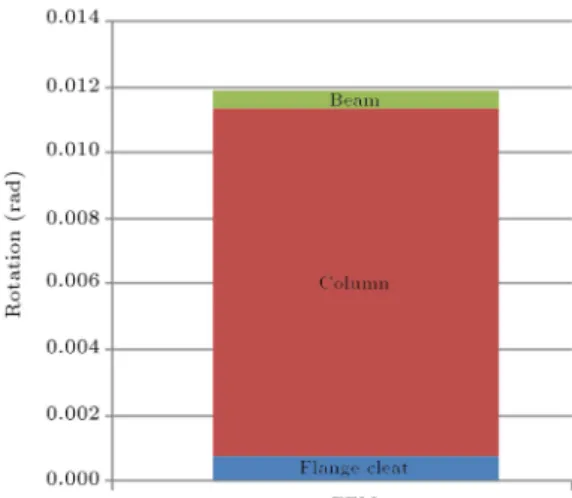
In order to ensure this thousand time stier value is valid in the analysis, a study has been carried out with the failure load for all components assigned with this value. It was found that there was no deection for this stier connection conguration. Therefore, the assumption of the thousand time stier value is appropriate for the component rotation analysis that obtains separated deections from overall deformation. The deections were recorded from one of the developed FEM models, as shown in Figure 4 for the specimen of DC250FC6 [26]. The overall rotation from nite element model was 11.91 mRad. According to the controlled rotation analysis, for 6 mm thickness ange cleat and at 4 kNm deformed shape, the rotations were 0.75 mRad due to ange cleat, 10.58 mRad of column deformation and 0.58 mRad contributed by beam component.
Among the two possible failure modes (ange cleat in bending and column ange in bending), the
Figure 4. The component rotations at 4 kNm in nite element analysis.
high rotation was contributed by the component that has thinner thickness of these components. Hence, the ange cleat and column ange are taken as the primary investigation variables to understand its structural performance. However, the beam depth and the ange cleat end bolt distance are also included in the study. 4.1. Flange cleat component analysis
4.1.1. Thickness of ange cleat
The component of ange cleat acts as a connector in joining the two other structural components. In a beam-to-column joint, ange cleats connect the beam to column and transform the forces and moments. The top ange cleat is in tension and the bottom ange cleat is in compression.
The thickness of the ange cleat has been iden-tied as one of the signicant parameters in the exural condition. The parametric study is carried out to investigate the structural performance for various thickness of ange cleat with neglected deformations of beam and column components. The increment of 1 mm has been assigned to the investigation range from 2 to 14 mm.
Figure 5 shows the deection contour with ange cleat component as the investigation variable. From the failure of the ange cleat, it can be realised that the deformation of the ange cleat has dominantly contributed to the overall deection at lower thickness of the ange cleat. The 2 mm top tension ange cleat buckled at peak load. As the ange cleat thickness increases to 14 mm, the deection has signicantly reduced at peak load as compared to 2 mm thickness ange cleat connection. The buckling eect also reduced for 14 mm thickness ange cleat. The stiness and the moment resistance of the developed joints have shown a gradual increment trend according to the recorded results, as shown in Figure 6. There is a nonlinear increment which is preliminary similar to the BS EN1993-1-8 structural prediction.
Figure 5. Deection contour for connection with ange cleat as dependent variable for (a) 2 mm thickness, and (b) 14 mm thickness of ange cleat.
Figure 6. Moment-rotation curves for component deformation of ange cleat with 2 mm to 14 mm ange cleat thickness.
4.1.2. Distance of end bolts
Distance of end bolts is one of the critical factors in the determination of structural failure. In BS EN1993-1-8 [4], the distance is described as m which is shown in Figure 7. The m greatly inuences the structural performance for a developed bolted connection. The investigated end bolts distance, e, ranges from 12 to 37 mm. The 12 mm end bolt distance is applied as it is slightly lower than minimum requirement of 1.2 do which is equivalent to 14.4 mm according to BS
EN1993-1-8.
At peak loads, the deformation of the ange cleat has been studied with dierent end bolt distances as shown in Figure 8. From the ange cleat failure observation, the deformation eect was less experi-enced by the bolt near to the angle corner of the top tension ange cleat. The deection become less and the stiness is increased as the bolt distance approaches the corner of the ange cleat. The moment-rotation behaviour was recorded in Figure 9.
Figure 7. The m distance in BS EN1993-1-8 [4].
Figure 8. Deformation contour of ange cleat with end distance of (a) 12 mm, and (b) 37 mm.
Figure 9. Moment-rotation curves for component deformation of ange cleat with dierent end bolt distances (e indicates the end bolt distance).
There is an inconsistence trend of value prediction at the plastic behaviour for dierent end bolt distances analysis. For the end distance ranges from 12 to 32 mm, at limitation of 0.1 Rad rotation, there is a clear and acceptable trend, without overlapping each other, for the moment-rotation characteristic. However, for 37 mm end bolt distance of the ange cleat, the analysis was terminated due to suspicious convergence problem, but it was able to give the results before 0.03 Rad rotation.
4.2. Column component analysis
The component of column is a structural member to transfer loading from the top building to the foundation
Figure 10. Bolt pull-out from column ange.
or footing. For a beam-to-column joint, column com-ponent transmits the exural loads from the beam to the sub-structure. The column should be sti enough to take the loads and moments from other structural members. For open I-section of column, the column ange is in tension and the column web located at bottom ange cleat is in compression mode.
The eective length from BS EN1993-1-8 stiness prediction has less eect on the structural performance. With stier value assigned to the material properties of bolt, beam and ange cleats, the failure mode will concentrate on column ange. In addition, since there is a limitation of the length for column ange by manufacturer, the end bolt distance is excluded from this investigation.
A desired failure on column ange is achieved in all investigated FEM models. Figure 10 shows the deformed shape of column ange. The investigated column ange thicknesses ranged from 2 mm to 14 mm as studied by ange cleat thickness. The bolt was pulled out from the column ange at peak load as it exceeded the column moment resistance. The moment-rotation behaviour has been recorded in Figure 11. 4.3. Beam component analysis
The beam component takes the dead and live loads from the slab and transfers to column through con-nectors. Beam dominantly resists the exural loads of the overall structure. The exural behaviour become signicant as the slender cold-formed steel sections are applied in the joint design.
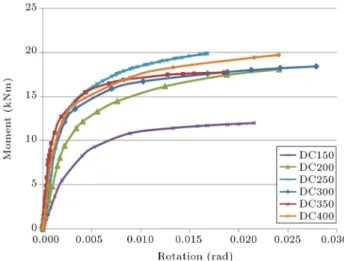
According to BS EN1993-1-8 design, beam nor-mally plays a role in joint classication. In order to resist the exural loads, the beam depth is the key parameter in the joint design. The beam depth can aect the moment resistance of a joint as the distance between tension zone and compression zone varies according to the beam depth. The investigated beam depth ranged from 150 to 400 mm. Web crushing was prevented by restricting the beam depth.
Figure 11. Moment-rotation curves for component deformation of column with 2 mm to 14 mm column ange thickness.
Figure 12. The deection contour for beam depth of (a) 150 mm, and (b) 400 mm.
From Figure 12, the deformation has been de-picted in the nite element analysis. There is a small rotation observed for beam depth of 150 mm. The failure mode of crushing at load point and the buckling eect at the beam web have decreased the rotational stiness of the beam component. For moment-rotation curve, as shown in Figure 13, there is no signicant trend of the curves due to buckling on the beam web. The beam experiences web buckling as the beam depth increases. The stiness and moment resistance are aected by the slenderness of the beam web. Since the obtained curves have less rotation capacity, the comparison is made on 0.01 Rad rotation.
4.4. Discussion on component analysis
The component rotation analysis for ange cleat, col-umn ange and beam was carried out to investigate the component behaviour at peak load. Basically, all studied geometrical parameters: ange cleat thick-ness, distance of end bolts at ange cleat, column
Figure 13. Moment-rotation curves for dierent beam depths as investigation variables.
ange thickness and beam depth have obtained desired moment-rotation behaviour for structural prediction.
The increment of ange cleat thickness and col-umn ange thickness led to stier joint conguration. The thicknesses of structural members were proved in the structural performance under exural loads. The end bolt distance also aected the rotational stiness of a joint. The stiness become greater when getting closer to the corner of the ange cleat. Moreover, as the beam depth increased, the rotational stiness was enhanced. However, web buckling between the ange cleats and crushing at loading point has altered the moment-rotation behaviour of joint.
In order to achieve ductile connection with no sudden collapse upon failure, BS EN1993-1-8 stated the failure should be controlled at ange cleat or column ange. This is proven by component deection analysis where the failure in beam depth was not able to achieve 0.02 Rad and 0.03 Rad rotation. Hence, it is recommended to use the beam with a depth not exceeding 250 mm to avoid the web crushing.
The obtained stiness of these components: ange cleat, column and beam are not suitable for combining in forming overall stiness. This is due to the fact that these components are associated with each other on the deformation. Therefore, it can be concluded that the geometrical parameters have aected the initial or secant rotational stiness signicantly and modelling is continued with the actual material behaviour assigned to all components in order to form a reliable formula-tion.
5. Formulation development 5.1. Investigated parameters
The parameters for the moment-rotation curve include the plastic moment of connection, Mp, the elastic
kp. The plastic moment resistance, Mp, is the limiting
point of the connection and can be calculated using the component method of BS EN1993-1-8.
The equations proposed by Fyre and Morris [16] are shown in Eq. (4):
ke;Fyre = 2:14 10 4t10:5h 1:5d 1:1l0:7: (4)
Ang and Morris [32] also proposed a power equation for semi-rigid beam-to-column connections. In this equation, the least square of parameter has reduced the eect of beam depth towards the initial stiness of the connection. The equation by Ang and Morris [32] is described in Eq. (5):
ke;Ang= 2:14 10 4t10:54h 1:06d 1:28l0:85: (5)
The above parameters are limited to the same type of bolt size and steel grade. The geometry of the con-nection is therefore the most important parameter for the rotational stiness. According to the component method of BS EN1993-1-8, the tension failure of the top-seat ange cleat connection is considered in terms of bending of the ange cleat, bending of the column ange, and development of transverse tension in the column web. In the case of cold-formed steel, since the thickness of the web is always twice the thickness of ange, the mode of failure can be expected to be in the ange.
In accordance with BS EN1993-1-8, the eective length of an equivalent T-stub involves the length of the ange cleat and column ange. In industry, the length of the connected ange cleat is often limited by the manufacturer's specication on the dimension of the C-channel section. By ignoring the material strength, the inuencing factor is the thickness of the cleat or column ange.
The beam depth is another factor that will also aect the connection's resistance. This contribution to the connection's exural behaviour has also been included in this paper. The investigated parameters are now extended to include the thickness of ange cleat, tfc, thickness of column ange, tcf, and beam depth,
Dbeam.
5.1.1. Elastic rotational stiness, ke
From the component rotation analysis, the thickness of column ange or ange cleat aects the moment-rotation of a joint. The stiness will keep increase as
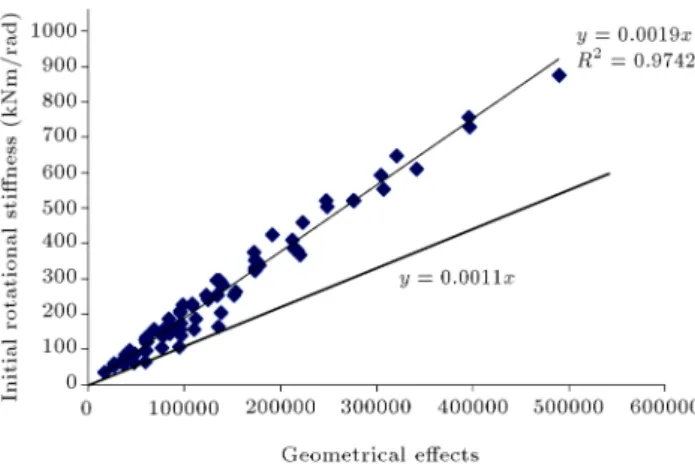
the thickness is increased. For practice, the thickness of 6 mm that is covered by hot-rolled steel is carrying less eect of thin-walled properties. Therefore, the ranges of the parameters are: 2 to 6 mm of column ange or ange cleat thickness and 150 to 250 mm of beam depth. A total of 75 nite element models were set-up in these combinations. From these models, the elastic rotational stiness was extracted from the moment-rotational behaviour of the models. The proposed elastic stiness equation, ke;pr, is as follows:
ke;pr = 1:1 10 3x; (6)
x =jt1:15
cf t1:17fc Dbeam1:62
k
: (7)
All units are in mm for geometrical dimension and kNm/Rad for rotational stiness. These equations were developed using least square method to obtain the power of the geometrical eects and linear regression method for elastic rotational stiness.
Figure 14 shows the least square graph. As can be seen, it was shifted to the conservative linear behaviour in order to obtain a reliable design. All depicted values are conservative to the experimental values and are safe to be used in the construction industry.
5.1.2. Plastic rotational stiness, kp
Table 3 shows the ratio of ke=kpas the steel propagates
from the elastic to plastic region in the moment-rotation curve.
From the experimental results, the ratio of elastic to plastic rotational stiness ranged from 1.88 to 2.24
Figure 14. Least square graph of elastic rotational stiness.
Table 3. Ratio of elastic and plastic rotational stiness. Model ke;exp kp;exp kRatioexp,
e;exp=kp;exp ke;FEM kp;FEM
RatioFEM,
ke;FEM=kp;FEM
Coecient, RatioFEM/Ratioexp
DC150FC6 97.6 43.5 2.24 93.4 41.7 2.24 1
DC200FC6 147.6 68.4 2.16 137.9 60.0 2.30 1.06
after the joint behaviour passed the transition point (Mp). For the numerical models, the ratio can be
controlled within 2.24 to 2.36. It can be assumed in the equations that a conservative cold-formed steel with top-seat ange cleat connection has a ratio of kp=ke=
0.4 where 10% of safety factor was added to the ratio of 2.36 and it became approximately 2.50.
5.1.3. Plastic moment resistance, Mp, and slope
tting coecient, C
From the preliminary study of BS EN1993-1-8, it was found that Eurocode gives less accurate prediction on elastic rotational stiness, but safe values were obtained for the plastic moment. Therefore, the tran-sition point at which the steel characteristic changes from elastic to plastic can be determined through the BS EN1993-1-8 component method. The procedures to obtain the moment resistance of top-seat ange cleat joint have been documented in BS EN1993-1-8.
The slope tting coecient, C, is applied to the exponential equation to determine the curve of the moment-rotation behaviour. It was found that the small value of C will give a gradual slope change, whereas greater value of C gives slow rate of slope change. The proposed equation is as Eq. (8). The C is xed as 0.1 where the rate is moderate to record the slope tting at plastic behaviour.
M = Mp
1 e (0:6ke+0:1)Mp
+ 0:4ke: (8)
5.2. Application of the proposed moment-rotation curve
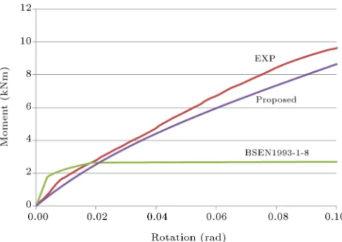
Figures 15 to 17 show the experimental test results, Eurocode curves, and proposed modied exponential curves, respectively, for the moment-rotation behaviour of the top-seat ange cleat connection. The trend line of the proposed equation is always lower than that of the experimental test results.
The proposed equation in Eq. (8) has shown a closed comparison with experimental results and
Figure 15. Comparison of moment-rotation curves between proposed, experimental and BS EN1993-1-8 models for DC150FC6.
Figure 16. Comparison of moment-rotation curves between proposed, experimental and BS EN1993-1-8 models for DC200FC6.
Figure 17. Comparison of moment-rotation curves between proposed, experimental and BS EN1993-1-8 models for DC250FC6.
improved the BS EN1993-1-8 structural prediction. For safety purpose, all predicted structural moment-rotation behaviour by the proposed equations is below the experimental results. Therefore, the proposed equations can be applied safely into the design stage in cold-formed steel top-seat ange cleat joint in light steel frame.
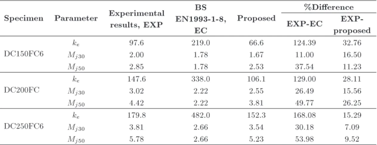
From Table 4, the percentage of dierence be-tween experimental results and BS EN1993-1-8 ranges from 168.08% to 124.39%, 11.00% to 30.18% and 37.54% to 53.98% for elastic rotational stiness, mo-ment resistance at 30 mRad and 50 mRad rotations, respectively. The dierences were closer between experimental results and the proposed equation with a dierence not more than 33% for the structural prediction.
6. Conclusions
This paper has presented three investigation models to determine the structural performance of top-seat ange cleat joints for light steel frame under exural loads.
Table 4. Summary of validation results. Specimen Parameter Experimental
results, EXP
BS EN1993-1-8,
EC
Proposed
%Dierence
EXP-EC
EXP-proposed DC150FC6
ke 97.6 219.0 66.6 124.39 32.76
Mj30 2.00 1.78 1.67 11.00 16.50
Mj50 2.85 1.78 2.53 37.54 11.23
DC200FC
ke 147.6 338.0 106.1 129.00 28.11
Mj30 3.02 2.22 2.55 26.49 15.56
Mj50 4.42 2.22 3.81 49.77 26.25
DC250FC6
ke 179.8 482.0 152.3 168.08 15.29
Mj30 3.81 2.66 3.54 30.18 7.09
Mj50 5.78 2.66 5.23 53.98 9.52
From the numerical, codied and experimental models, the following conclusions are presented:
i. Preliminary study was conducted to get the evi-dence of the suitability in adopting BS EN1993-1-8 to joint behaviour with thin-walled behaviour of cold-formed steel top-seat ange cleat joint. There is a signicant dierence in the structural predic-tion of BS EN1993-1-8 for structural predicpredic-tion of mechanical properties.
ii. Component rotation analysis was performed to investigate the component behaviour under peak exural load. The increment in thickness of ange cleat, end bolt distances, thickness of column ange and beam depth led to the growth of the stiness.
iii. A modied exponential equation has been pro-posed to represent the moment-rotation curve for cold-formed steel with top-seat ange cleat connec-tions as shown in Eq. (8). The proposed equation can improve the BS EN1993-1-8 prediction from 168.08% dierence compared to experimental re-sults, to 7.09% dierence.
Acknowledgments
This research was funded by research grants (03H76, 4F258, 4F647 and 02G88) from the Research Manage-ment Centre, Universiti Teknologi Malaysia and the Ministry Of Higher Education (Malaysia) (MOHE). The nancial support provided is gratefully acknowl-edged. The technical support from the Laboratory of Structures and Materials of UTM is also appreciated. Nomenclature
Bbeam Width of beam section
Bcol Width of column section
C Curve-tting coecient
Dbeam Depth of beam section
Dcol Depth of column section
FT;1;Rd Design strength of mechanism type 1
FT;2;Rd Design strength of mechanism type 2
fy Component design strength
ke Elastic rotational stiness
kp Plastic rotational stiness
ke;EC Elastic rotational stiness from BS
EN1993-1-8
ke;exp Elastic rotational stiness of
experimental model
ke;FEM Elastic rotational stiness of nite
element model
ke;pr Proposed initial rotational stiness
kp;pr Proposed plastic rotational stiness
ksec30 Secant rotational stiness at 30 mRad
rotation
ksec50 Secant rotational stiness at 50 mRad
rotation
kFyre Stiness developed by Fyre and Morris
kAng Stiness developed by Ang and Morris
M Applied moment
Mj30 Moment resistance at 30 mRad
rotation
Mj50 Moment resistance at 50 mRad
rotation
Mj30;EC Moment resistance at 30 mRad
rotation from BS EN1993-1-8 Mj50;EC Moment resistance at 50 mRad
rotation from BS EN1993-1-8 Mj30;exp Moment resistance at 30 mRad
rotation of experimental model Mj50;exp Moment resistance at 50 mRad
rotation of experimental model Mj30;pr Proposed moment resistance at
Mj50;pr Proposed moment resistance at
50 mRad rotation
Mp Plastic moment resistance of
connection
tbeam Thickness of beam section
tcf Thickness of column ange
tcol Thickness of column section
tfc Thickness of ange-cleat
x Geometrical parameters for least square equation
Connection rotation
References
1. Bijlaard, F. \Eurocode 3, a basis for further develop-ment in joint design", J. Constr. Steel Res., 62, pp. 1060-1067 (2006).
2. Wong, M.F. \Bolted moment connections in cold-formed steel beam-column sub-frames" Master thesis, The Hong Kong Polytechnic University, Hong Kong (2002).
3. Mujagic, J.R.U. and Easterling, W.S. \Connections in cold-formed steel framing - Designing with AISI 2007: Specication and application overview", STRUC-TURE Magazine, pp. 9-11 (August 2009).
4. British Standards Institution. Eurocode 3 \Design of steel structures. Part 1.8: Design of Joint", BS EN 1993-1-8. U.K. BSI (2005).
5. Abdalla, K.M. and Chen, W.F. \Expanded database of semi-rigid steel connections", Comput. Struct., 56(4), pp. 553-564 (1995).
6. Kameshki, E.S. and Saka, M.P. \Genetic algorithm based optimum design of nonlinear planar steel frames with various semi-rigid connections", J. Constr. Steel Res., 59, pp. 109-134 (2003).
7. Daryan, A.S. and Yahyai, M. \Behavior of bolted top-seat angle connections in re", J. Constr. Steel Res., 65(7), pp. 531-541 (2009).
8. Kishi, N. and Chen, W.F. \Moment-rotation relations of semirigid connections with angles", J. Struct. Eng., 116, pp. 1813-1834 (1990).
9. Faella, C., Piluso, V. and Rizzano, G., Structural Steel Semirigid Connections - Theory, Design and Software, CRC Press (2000).
10. Loureiro, A., Reinosa, J.M., Gutierrez, R. and Moreno, A. \New proposals on the calculation of the exural resistance in angle connections", J. Constr. Steel Res., 67, pp. 613-622 (2011).
11. Rathbun, J.C. \Elastic properties of riveted connec-tion", Transaction of the ASCE, 101, pp. 524-563 (1936).
12. Tarpy, T.S. and Cardinal, J.W. \Behavior of semi-rigid beam-to-column end plate connection", Proceedings of the International Conference: Joints in Struc-tural Steelwork, Teesside Polytechnic, Middlesbrough, Cleveland, U.K. 2.3-2.25 (1981).
13. Melchers, R.E. and Kaur, D. \Behaviour of frames with exible joints", Proceedings of 8th Australia Con-ference Mechanical of Structural Materials, Newcastle, Australia, pp. 271-275 (1982).
14. Lui, E.M. and Chen, W.F. \Analysis and behavior of exibly-jointed frames", Eng. Struct., 8(2), pp. 107-118 (1986).
15. Razzaq, Z. \End restraint eect on steel column strength", J. Struct. Eng., 109(2), pp. 314-334 (1983). 16. Frye, M.J. and Morris, G.A. \Analysis of exibly connected steel frames", Can. J. Civil Eng., 2(3), pp. 280-291 (1975).
17. Sommer, W.H. \Behaviour of welded header-plate connection", Master Thesis, University of Toronto, Canada (1969).
18. Kishi, N. and Chen, W.F. \Database of steel beam-to-column connections", Structural Engineering Report No. CE-STR-86-26, School of Civil Engineering, Pur-due University, West Lafayette, IN (1986).
19. Yee, Y.L. and Melchers, R.E. \Moment-rotation curves for bolted connections", J. Struct. Eng., 112(3), pp. 615-635 (1986).
20. Batho, C. and Lash, S.D. \Further investigations on beam and stanchions connection, including connec-tions encased in concrete; together with laboratory investigations on a full-scale steel frames", Final Re-port of the Steel Structures Research Committee, Department of Scientic and Industrial Research. His Majesty's Stationery Oce, London (1936).
21. Colson, A. and Louveau, J.M. \Connections incidence on the inelastic behavior of steel structures", Proceed-ings of the Euromech Colloquium, No. 174 (1983). 22. Kishi, N., Chen, W.F., Matsuoka, K.G. and Nomachi,
S.G. \Moment-rotation relation of top- and seat-angle with double web-angle connections", Proceedings of the State-of-the-Art Workshop on Connections and the Behavior, Strength and Design of Steel Structures, R. Bjorhovde, J. Brozzetti and A. Colson, Eds., Superieure de Cachan, France (May 25-27, 1987). 23. Tan, C.S., Tahir, M.M. and Shek, P.N.
\Experimen-tal investigation on angle cleat connections for cold-formed steel sections", Advanced in Steel and Alu-minium Structures, Research Publishing, Singapore, pp. 186-192 (2011).
24. Tan, C.S., Lee, Y.H., Lee, Y.L., Mohammad, S., Sulaiman, A., Tahir, M.M. and Shek, P.N. \Numerical simulation of cold-formed steel top-seat ange cleat connection", Jurnal Teknologi, Sciences & Engineer-ing, 61(3), pp. 63-71 (2013).
25. Lee, Y.H., Tan, C.S., Lee, Y.L., Tahir, M.M., Mo-hammad, S. and Shek, P.N. \Numerical modelling of stiness and strength behaviour of top-seat ange-cleat connection for cold-formed double channel sections", Applied Mechanics and Materials, 284-287, pp. 1426-1430 (2013).
26. Lee, Y.H., Tan, C.S., Mahmood, T. and Shahrin, M. \Numerical modelling and validation of light gauge steel top-seat ange-cleat connection", J. Vibroeng., 14(3), pp. 1104-1112 (2012).
27. Yu, W.K., Chung, K.F. and Wong, M.F. \Analysis of bolted moment connections in cold-formed steel beam-column sub-frames", J. Constr. Steel Res., 61, pp. 1332-1352 (2005).
28. Thacker, B.H., Doebling, S.W., Hemez, F.M., Ander-son, M.C., Pepin, J.E. and Rodriguez, E.A. \Concepts of model verication and validation", Los Alamos Na-tional Laboratory, United State of America (October 2004).
29. Chen, W.F., Practical Analysis for Semi-rigid Frame Design, World Scientic, Singapore (2000).
30. Wong, M.F. \Bolted moment connections in cold-formed steel beam-column sub-frames", Master thesis. The Hong Kong Polytechnic University, Hong Kong (2002).
31. Lee, Y.H., Tan, C.S., Tahir, M.M., Mohammad, S., Shek, P.N. and Lee, Y.L. \Inuence of angle thickness towards stiness and strength prediction for cold-formed steel top-seat ange cleat connection", Applied Mechanics and Materials, 479-480, pp. 1144-1148 (2014).
32. Ang, K.M. and Morris, G.A. \Analysis of three-dimensional frames with exible beam-column connec-tions", Can. J. Civil Eng., 11, pp. 245-254 (1984).
Biographies
Yeong Huei Lee obtained his PhD from Faculty of Civil Engineering, Universiti Teknologi Malaysia (UTM) in 2015. His research interests include, but not limited to, light steel framing, cold-formed steel, con-nection design, structural stability, rapid construction system and nite element analysis.
Cher Siang Tan is a senior lecturer in the Depart-ment of Structures and Materials, Faculty of Civil Engineering, Universiti Teknologi Malaysia (UTM). He has strong research interest in the eld of structural steelwork, especially cold-formed steel, thin-walled structures and lightweight construction. He was also post-doctorate at Ecole Polytechnique Federale de Lausanne (EPFL) in Switzerland.
Shahrin Mohammad is a Professor in Department of Structures and Materials, Faculty of Civil Engineer-ing, Universiti Teknologi Malaysia (UTM). He jointly published 10 books, monograph and standards. To date, he had jointly written more than 70 journals, seminar and conference papers both at the national and international levels. These papers addressed research ndings as well as sharing experiences on the teaching and learning activities. Apart from this, 12 technical and academic administrative papers had also been written.
James B.P. Lim is currently a senior lecturer in The University of Auckland, New Zealand. His research interests lie in the eld of steel-framed structures. With particular reference to portal frames and cold-formed steel. His research is dominated in trying to understand fundamental structural behaviour for which he employ a combination of numerical modelling and full-scale testing.
Ross Johnston is a PhD candidate in School of Architecture, Planning and Civil Engineering, Queen's University Belfast, United Kingdom. His research interests lie within Building Information Modelling (BIM) and Finite Element Analysis (FEA). He also has experience within sustainable construction and design/analysis compatibility.

![Figure 7. The m distance in BS EN1993-1-8 [4].](https://thumb-us.123doks.com/thumbv2/123dok_us/8385072.2227854/7.892.476.780.151.396/figure-m-distance-bs-en.webp)