Real-Time and Embedded Systems
Chang Liu, David Fleeman, Eric Aber, Lonnie Welch, and David Juedes Center for Intelligent, Distributed and Dependable Systems
School of Electrical Engineering and Computer Science Russ College of Engineering and Technology
Ohio University Athens, Ohio 45701, U.S.A.
http://ace.cs.ohiou.edu/~changliu
Abstract. We propose a model-driven resource management technique designed for online resource management of distributed real-time and embedded systems. We have implemented this technique in the QARMA resource manager and related de-sign tools. This paper describes a visual modeling tool used by QARMA, the speci-fication languages it generates, as well as QARMA’s underlying model and software architecture.
1
Introduction
We address the problem of conducting online resource management for distributed real-time and embedded (DRE) systems [9]. In DRE systems, typically, multiple distributed applications work together to process real-time tasks. Each application requires certain amount of resources to complete its designated task. Some applications are designed to use different amounts of resources when the requirement on its performance and quality changes. Such applications are sometimes calledflexible applications [7, Chapter 10]. When such applications are present in DRE systems, it is possible to adjust resource allocation at runtime so that the overall systems with fixed amount of resources can perform better in different situations. The goal of online resource management for DRE systems is to make appropriate adjustment to resource allocation at appropriate time so that the overall system provide satisfactory benefits to its users.
We adopt a model-driven approach to address this problem. The DRE system models described in [12, 13], on which our work is based, showed that a clearly-defined underlying model for both the DRE system and its environment is the basis of resource allocation algorithms. In addition, with a model, we can 1) check the model before the system is built; 2) provide basis for system certification after the system is implemented; and 3) pre-compute necessary data so that the resource manager can perform better at runtime.
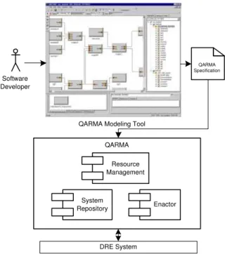
We design a Quality-based Adaptive Resource Management Architecture (QARMA) to realize our resource management technique [3]. The QARMA Resource Manager, which is implemented in the context of CORBA, has three major components: the Resource Man-agement Service, the System Repository Service, and the Enactor Service. The System Repository Service provides a storage for both static and dynamic information about com-puting resources and software applications in an DRE system. In other words, the system repository contains all concrete information of the DRE system with respect to the sys-tem model. TheResource Management Servicemakes decision on resource allocation based on the information in the system repository. The Enactor Service carries out high-level QARMA decisions by invoking lower-level enactors provided by CORBA middleware or
application software. Fig. 1 depicts the QARMA resource management architecture as well as a software engineering process that adopts QARMA, which is explained in greater detail in Sec. 4. QARMA Specification QARMA Resource Management System Repository Enactor Software Developer
QARMA Modeling Tool
DRE System
Fig. 1.An overview of the QARMA resource management architecture and process.
2
An DRE System Model for Dynamic Resource Management
The resource allocation of astatic DRE system, which does not change over time, can be modeled as a three-tupleDREs= (R, S, A) where
– R is a set of resource supplies, such as CPUs, memory, and network connections;
– S is a set of software applications that demand resources; and
– A ={a|a∈R×S×Real}, whereReal is the set of real numbers, is a set of quan-tified mappings between resources and software applications that reflect the resource allocation.
A dynamic DRE system, whose resource allocation could change at runtime, can be modeled as a seven-tupleDREd = (R, S, P, AttrT ype, Attr, A,B) where
– R is a set of resource supplies;
– S is a set of software applications that demand resources;
– P is a set of sequences of software applications;
– AttrT ype is a set of symbolic names of attributes that describe resource, software ap-plication, and path properties that could be of interest to a resource manager;
– Attr:{R∪S∪P} ×AttrT ype→R∪S∪Real∪ {unknown, invalid}, whereunknown and invalid are two predefined symbols, is a function that determines the values of resource, software application, or path attributes;
– A ={a| a∈ R×S×Real}is a set of quantified mappings that reflect the resource allocation; and
– Bis a function that maps a resource allocation to a real number, which represents the overall benefits provided by the DRE system to its users [2, 1].
A dynamic DRE system model must include the set of resource and software application attributes because they specify resource supplies and demands in the system and are the basis of online resource allocation decisions. Path attributes typically represent end-to-end QoS requirements.
Given a dynamic DRE system model, one can potentially perform the following three tasks at design time:
1. Check resource allocations, identify feasible ones, and detect infeasible ones; 2. Compute information that may be needed by the resource manager at runtime; and 3. Verify algorithms and strategies used by the resource manager, which helps system
certification of DRE systems with dynamic resource management. Next, we use an example to illustrate how to perform the first task.
A resource allocation is infeasible if more software applications are assigned to a single resource than it is capable to service. For example, if three applicationsapp1,app2, andapp3 are assigned to the same single-processor computer. All three applications are periodical and have the same period of 30 seconds. Suppose the execution time ofapp1 is 5 seconds,app2 10 seconds, andapp3 20 seconds when they function at their respective desirable service levels. Apparently, this allocation is infeasible because the theoretical CPU workload of the computer exceeds 100%.
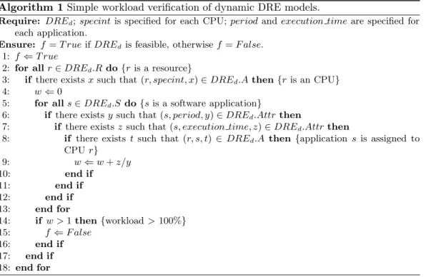
The algorithm for simple workload verification is shown in Algorithm 1. The complexity of the algorithm isO(|R| × |S|). This algorithm assumes thatperiod andexecution time are two attributes and that all software applications have only one service level1
.
The model presented in this section is simpler than the models in [12, 13] partly because no concrete attribute types, such as CPU speed, maximum path latency, are defined in this model. Our intention is to simplify the representation of the model and pave the way for automatic verification without losing any expressive power. The models in [12, 13] can be fully expressed in this model. Indeed, this model is more expressive because new, arbitrary attributes can be included.
3
Capturing the DRE System Model in a Specification Language
To make the information of the DRE system model available to the QARMA resource manager, we design the QARMA specification language, in which a software developer or a tool can encode an DRE system model. A QARMA system resource specification written in this language consists of two sections, the resource supply specification section and the resource demand specification section. Theresource supply specification describes CPU, memory, and network resources available in the DRE system. Theresource demand specificationdescribes various levels of static resource consumptions of software applications in the system. The current version of the specification language is less generic than the the formal DRE system model described in Sec. 2. It is tailored for DRE systems in which CPU, memory, and network bandwidth are the subjects of resource contention. Therefore, the language provides keywords such asMemory,Network,SpecInt andSpecFp2.
1
This algorithm can be easily extended to cope with software applications with multiple service levels. The complexity of the extended algorithm is stillO(|R| × |S|).
2
Algorithm 1Simple workload verification of dynamic DRE models.
Require: DREd;specintis specified for each CPU;periodandexecution timeare specified for
each application.
Ensure: f=T rueifDREdis feasible, otherwisef=F alse.
1: f⇐T rue
2: for allr∈DREd.Rdo{ris a resource}
3: if there existsxsuch that (r, specint, x)∈DREd.Athen{ris an CPU}
4: w⇐0
5: for alls∈DREd.S do{sis a software application}
6: if there existsysuch that (s, period, y)∈DREd.Attrthen
7: if there existsz such that (s, execution time, z)∈DREd.Attrthen
8: if there exists tsuch that (r, s, t) ∈ DREd.A then {applications is assigned to
CPUr} 9: w⇐w+z/y 10: end if 11: end if 12: end if 13: end for 14: if w >1then{workload>100%} 15: f⇐F alse 16: end if 17: end if 18: end for
For example, the QARMA specification segment in Fig. 2 specifies a host computer with 128MB memory, a network interfaceeth0, and an CPU that is rated at 2.5 for integer computation and 2.5 for float point number computation under the SPEC3
rating. This host computer runs the Linux kernel version 3.2.1 and the Java virtual machine version 1.4.1.
Host host1 {
SpecInt 2.5; SpecFp 2.5; Memory 128MB;
Capabilities { linux, kernel 3.2.1, java 1.4.1}
Network { Interface eth0; } }
Fig. 2.A QARMA specification segment that specifies computing resources in a host computer.
4
Generating the Specification from a Visual Modeling Tool
While the QARMA specification language is a straightforward and easy-to-use language for DRE system designers, models represented by QARMA specifications, especially their network topologies, software path configurations, and potential resource allocations, may not be simple to decode because the QARMA specification language is, after all, a single dimensional text language and is inherently limited in its capability to intuitively represent3
multiple dimensional relationships. To overcome this deficiency of the QARMA specification language, we develop the QARMA visual modeling tool that enables DRE system designers to graphically construct and examine QARMA models, which can be encoded in QARMA specifications automatically generated by the QARMA modeling tool.
The QARMA visual modeling tool is based on the Generic Modeling Environment (GME) [6, 5], a general-purpose, configurable modeling environment with a modular, ex-tensible architecture that enables users to create domain-specific modeling tools. VEST (Virginia Embedded Systems Toolkit), a GME-based tool, is a customized toolkit for con-structing and analyzing component-based DRE systems [10, 11]. VEST provides a library that supports descriptions of hardware components and networks. The QARMA modeling tool extends the VEST library and, among other enhancements, adds support for the de-scriptions of software applications and paths. The QARMA tool enables an DRE system designer to capture in a graphic model all aspects of a DRE system that is of interest to the QARMA resource manager.
Fig. 1 contains a screenshot of the QARMA visual modeling tool, which provides the following main “building blocks” in its library:
– hardware
host models uni-processor computers;
switch models network switches;
processor models CPUs;
memory models main memory in a host computer;
network interface models network interfaces in a host computer.
– software
paths consists a sequence of software applications which performs system-level task together;
software applications models individual software applications in the DRE system;
extrinsic attributes models properties of the environment;
service attributes models adjustable properties of software applications;
benefit tables models how overall system benefits are perceived by DRE system users. In a software engineering process that adopts QARMA, the DRE system designer con-structs a QARMA model interactively. He starts with either an empty model or a similar model copied from a previous project. He can then
– add “building blocks” in the library piece by piece to the model,
– create, adjust, or delete associations between elements in the model,
– delete elements from the model, or
– specify or modify properties of an element.
He can visually examine the model at any time during the process. As shown in fig. 1, when he is satisfied with the model, he can invoke the specification generation feature and instruct the tool to automatically generate a QARMA specification of the model, which can be provided to the QARMA resource manager later.
The QARMA modeling tool enables DRE system designers to visually construct DRE system models using existing “building blocks”. This is more efficient than editing QARMA specification text directly. Furthermore, the QARMA modeling tool guarantees that the generated QARMA specifications are error-free, which further improves designer efficiency. Visual modeling tools such as UML-MAST [8, 4] enables visual modeling and analysis of real-time systems. They are pure design-time tools and do not have an interface with runtime mechanisms. The QARMA modeling tool, on the other hand, does interface with
the runtime QARMA resource manager through the QARMA specification, which is the output of the QARMA tool. The QARMA specification will be read in by the QARMA resource manager and stored in the system repository. These information provides the basis for QARMA’s decision making at runtime.
5
Summary
In conclusion, our model-driven technique for online resource management of DRE systems consists of a modeling tool, a specification language, and a system architecture that has been implemented in the context of CORBA. This approach enables DRE system developers to intuitively construct system models, automatically generate system resource specifications, and use the QARMA resource manager to improve DRE systems so that they are more flexible, perform better in different situations with fixed amount of resources, and provide more overall benefits to DRE system users.
We have applied our model-driven technique on a real-world example and obtained satisfactory experimental results, which will be reported in a different paper due to space constraints.
References
1. D. Andrews, R. Vemuri, D. Chelberg, D. Fleeman, D. Parrott, L. Welch, and S. Brandt. A framework for using benefit functions in complex real-time systems. Journal of Parallel and Distributed Computing Practices, to appear.
2. D. Andrews, L. Welch, D. Chelberg, and S. Brandt. A framework for using benefit functions in complex real time systems. Inthe 10th Workshop on Parallel and Distributed Real-Time Systems (WPDRTS’2002), April 2002.
3. D. Fleeman, M. Gillen, A. Lenharth, M. Delaney, L. Welch, D. Juedes, and C. Liu. Quality-based adaptive resource management architecture (QARMA): A CORBA resource manage-ment service. In The 12th International Workshop on Parallel and Distributed Real-Time Systems (WPDRTS’2004), Santa Fe, New Mexico, U.S.A., April 26-27, 2004.
4. M. Gonzlez Harbour, J. J. Gutirrez Garca, J. C. Palencia Gutirrez, and J. M. Drake Moy-ano. MAST: Modeling and analysis suite for real-time applications. In the 13th Euromicro Conference on Real-Time Systems (ECRTS’01), Delft, The Netherlands, June 13-15, 2001. 5. G. Karsai, M. Maroti, A. Ledeczi, J. Gray, and J. Sztipanovits. Composition and cloning in
modeling and meta-modeling.IEEE Transactions on Control System Technology, March 2004. 6. A. Ledeczi, M. Maroti, A. Bakay, G. Karsai, J. Garrett, C. Thomas IV, G. Nordstrom, J. Sprin-kle, and P. Volgyesi. The generic modeling environment. In Workshop on Intelligent Signal Processing, Budapest, Hungary, May 2001.
7. J. W. S. Liu. Real-Time Systems. Prentice Hall, 2000.
8. J. L. Medina Pasaje, M. Gonzlez Harbour, and J. M. Drake. MAST real-time view: A graphic UML tool for modeling object-oriented real-time systems. Inthe 22nd IEEE Real-Time Systems Symposium (RTSS’01), pages 245–256, London, UK, December 3-6, 2001.
9. B. Ravindran, L. R. Welch, and B. A. Shirazi. Resource management middleware for dynamic, dependable real-time systems. The Journal of Real-Time Systems, 20:183–196, 2000.
10. J. Stankovic. VEST: A toolset for constructing and analyzing component based embedded systems. Springer-Verlag Lecture Notes, pages 390–402, October 2001.
11. J. A. Stankovic, R. Zhu, R. Poornalingam, C. Lu, Z. Yu, M. Humphrey, and B. Ellis. VEST: An aspect-based composition tool for real-time systems. InReal-Time Applications Symposium, May 2003.
12. L. R. Welch, B. Ravindran, B. A. Shirazi, and C. Bruggemen. Specification and modeling of dynamic, distributed real-time systems. Inthe 19th IEEE Real-Time Systems Symposium (RTSS’98), pages 72–81, Madrid, Spain, December 2-4, 1998.
13. L. R. Welch, P. V. Werme, B. A. Shirazi, C. D. Cavanaugh, L. Fontenot, E.-N. Huh, and M. W. Masters. Load balancing for dynamic real-time systems. Cluster Computing, 3(3):125– 138, 2000.