Sum-Rate Maximization of Coordinated Direct and
Relay Systems
(Invited Paper)
Fan Sun, Petar Popovski, Chan Dai Truyen Thai, and Elisabeth de Carvalho
Department of Electronic Systems, Faculty of Engineering and ScienceAalborg University, DK-9220 Aalborg, Denmark Email: {fs,petarp,ttc,edc}@es.aau.dk
Abstract—Joint processing of multiple communication flows in wireless systems has given rise to a number of novel transmission techniques, notably the two-way relaying based on wireless network coding. Recently, a related set of techniques has emerged, termed coordinated direct and relay (CDR) transmissions, where the constellation of traffic flows is more general than the two-way. Regardless of the actual traffic flows, in a CDR scheme the relay has a central role in managing the interference and boosting the overall system performance. In this paper we investigate the novel transmission modes, based on amplify-and-forward, that arise when the relay is equipped with multiple antennas and can use beamforming. We focus on one representative traffic type, with one uplink and one downlink users and consider the achievable sum-rate maximization relay beamforming. The beamforming criterion leads to a non-convex problem and we introduce a low-complexity iterative solution, as well as derive a sum-rate upper performance bound. Numerical results demonstrate an obvious benefit from the usage of multiple antennas at the relay node.
Index Terms—Analog network coding, amplify-and-forward, beamforming, a priori information.
I. INTRODUCTION
Recently there have been extensive studies on cooperative, relay-based transmission schemes for extending cellular cover-age or increasing diversity. Several basic relaying transmission techniques have been introduced, such as amplify-and-forward (AF) [1], decode-and-forward (DF) [2] and compress-and-forward (CF) [3].
These transmission techniques have been applied in one-way, two-way or multi-way relaying scenarios. There has been a particularly high interest in two-way relaying scenarios [4], [5], [6], where throughput gains have been demonstrated by utilizing the ideas of wireless network coding. The two underlying principles used in designing throughput–efficient schemes with wireless network coding:
1) Aggregation of multiple communication flows: instead of transmitting each flow independently, the principle of network coding is used in which flows are sent/processed jointly;
2) Intentional cancellable interference: network coding al-lows interference and simultaneous usage of the shared wireless medium, leaving to the receivers to remove the adverse impact of interference by using any side information.
Leveraging on these principles, we have proposed schemes with non-regenerative AF relaying in [7], [8] that feature more
general traffic patterns compared to the two-way relaying. These schemes are termed coordinated direct/relay (CDR) transmissions. The CDR transmission considers scenarios where one direct user (UE) and one relayed UE are served in uplink/downlink. The relayed UE is assumed to have no direct link to the base station (BS) due to large path loss and relies only on the amplified/forwarded signal from the relay in order to decode the signal from the BS. Transmission schemes that are related to some of the schemes have appeared before in [9], [10], [11].
Each user might have a downlink or uplink traffic. Hence, there are different traffic configurations. We focus on one representative traffic type with one relayed uplink UE and one direct downlink UE. This case displays the merits of analog network coding in a setting that is more general than the usual two-way relay scenario. Furthermore it showcases the principle of overheard information where a node overhears a signal that is not intended to itself and uses it as a prioriinformation to cancel interference in an ulterior transmission phase.
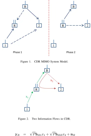
In the scheme on Fig. 1, we assume that a relayed UE has one signal to deliver to the BS through the assistance of the relay station, while a direct user wants to receive a signal from the BS. Notice in a conventional wireless cellular system, these signals are sent over two orthogonal uplink and downlink phases for the two separate information flows, respectively. Instead in the CDR system, the BS first sends the signal to the direct UE and simultaneously the relayed UE transmits the signal to the relay station in phase 1. The relay receives two signals: the desired signal from the UE and an interfering signal from the BS. It does not decode the signals but instead forward them in phase 2 using the principle of analog network coding. The simultaneous two-flow transmissions improve thespectral efficiencycompared to the conventional method. The key points are the BS can use the
a priori information to perform self-interference cancellation
and enable interference-free reception and decoding; the direct UE can use the overheard information in phase 2 to help decoding the desired signal.
Differently from the previous works, the usage of multiple antennas at the relay permits to manage the interference and boost the overall system performance through beamforming. This is a significant conceptual difference compared to the original CDR schemes, while the usage of multiple antennas at the BS and the UEs is a clear future work. We consider AF operation at the relay, assuming that the relay and the reception nodes have a perfect channel state information (CSI). Our objective is to maximize the achievable sum-rate of the system. Our design shows that the overall system performance is improved by allowing the relay beamformer to deliver the interfered signal to both the BS and the direct UE in phase 2. Meanwhile,
• the BS completely cancels the self-interference;
• the direct UE applies linear interference minimization receiver to decode the desired signal.
The sum-rate maximization is achieved by a low-complexity iterative algorithm. Simulation results show a clear tradeoff between the rate maximization of individual information flows. The gain via possessing multiple relay antennas is also shown compared to the original CDR transmission.
Notation: We use uppercase and lowercase boldface letters
to represent matrices and vectors, respectively.⊗refers to the Kronecker product and||·||2
F denotes the Frobenius norm of a matrix.Iis the identity matrix.
II. SYSTEMOVERVIEW
The basic setup is the scenario in Fig. 1 with one BS, one relay, and two UEs. The relay is equipped withM antennas. The BS and the UEs are equipped with one antenna only. The transmission from the relayed UE to the relay has the same duration as the transmission from the relay to the BS. The relay is deployed to help the relayed UE which has no direct link to the BS due to large path loss.
We consider the multi-antenna relay beamforming design where there are two information flows: the relayed UE (UE 1) deliversx1to the BS and the BS transmitsx2to the direct UE
(UE 2). The conventional system will create two orthogonal transmissions for separate information flows, while the CDR system enables simultaneous transmissions and thus improves the system spectral efficiency. Here we illustrate the two-phase CDR transmission in Fig. 1. In the first slot, UE 1 transmits
x1to the relay and the BS deliversx2to UE 2 simultaneously.
At the same time, UE 2 overhears the signal from UE 1 and the relay also receives the signal from the BS. Then the relay forwards the received physical layer network-coded signal to both the BS and the direct UE in the second slot. The BS has the capability to use the a priori information it transmits in the first slot to perform self-interference cancellation.
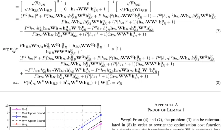
In summary, Fig. 2 describes the two flows and the analog network coding principle at the relay. The green lines describe the uplink traffic from the relayed UE and the red lines represent the downlink to the direct UE. This depicts a more general traffic pattern compared to the two-way relaying.
In this CDR system, each channel is assumed to be an independent complex Gaussian random variable with zero
mean and unit variance. All links are assumed to be static within the two slots. Assume P to be the transmit power of the BS and each UE, the received signals at the relay and UE 2 in the first slot are
B
R
Phase 1 1
2
B
R
1
2
Phase 2
Figure 1. CDR MIMO System Model.
B
Single
antenna
UEs
Single
antenna
BS
x
R 2
x1
x2
1
Reference
scheme:
the
beamforming
at
the
relay
node
aims
at
altruism
via
interference
nulling
to
the
direct
UE.
CDR1:
the
relay
beamforming
aims
at
egoism
via
maximizing
the
SNR
of
the
relayed
UE.
The
relayed
UE
uses
the
overheaded
information
in
the
first
phase.
CDR2:
balancing
between
Altruism
and
Egoism.
The
target
is
sum
rate
maximization
of
both
UEs.
It
can
be
seen
as
a
tradeoff
between
Altruism
and
Egoism.
Figure 2. Two Information Flows in CDR.
yR = √
PhR1x1+
√
PhRBx2+nR y2[1] =
√
P h21x1+
√
P h2Bx2+n2[1] (1)
wherenR is the complex white Gaussian noise vector at the relay with the covariance matrix E[nRnHR] =I and n2[1] is
the complex white Gaussian noise variable at UE 2 in the first slot with unit variance1. The received signals at the BS and UE 2 in the second slot are
yB = hBRxR+nB
y2[2] = h2RxR+n2[2] (2)
where the signal vectors transmitted from the relay is in the form xR = WyR with W being the M ×M relay beamforming matrix. At the relay,Wis used here to linearly process M ×1 received signal vector and form the M ×1 transmit signal vector without loss of generality.nBandn2[2]
are the complex white Gaussian noise variables with unit
1In this work, we assume the variance of each noise component is
variance each at the BS and UE 2 respectively. The relay transmission power2 is
E[xHRxR]
=Tr(PWhRBhHRBW
H+PWh
R1hHR1W
H+WWH)
=P(hHRBWHWhRB+hHR1W HWh
R1) +||W||2F =PR. III. SUM-RATEMAXIMIZATION FORCOORDINATED
RELAYBEAMFORMINGDESIGN
From the previous illustration, the relay has the capability to beamform the received network-coded signal and forwards the beamformed signal to both the BS and the direct UE in the second phase of the CDR transmission. Via sum-rate maximal relay beamforming design, the overall CDR system performance is enhanced by allowing the relay to balance between maximizing the rate of the transmission from the relayed UE to the BS and rate of the transmission from the BS to the direct UE. The central role of the relay in balancing the two information flows can be observed in Fig. 2. We also incorporate an iterative low-complexity algorithm to achieve the sum-rate maximization and a sum-rate upper bound.
A. Problem Formulation
The sum-rate maximization beamforming design problem can be mathematically formulated as
arg max
W (R1+R2) s.t. P(hHRBW
H
WhRB+hHR1W H
WhR1)
+||W||2
F =PR
whereR1andR2denote the rate expressions for the
transmis-sion of x1 andx2, respectively. The rate expression for each
information flow can be written as
R1=
1
2log2(1 + SNR1)
R2=
1
2log2(1 + SINR2)
where SNR1 is the SNR expression for the BS to decode
x1 and SINR2 is the SINR expression for the direct UE to
decode x2. And the factor 12 is due to the two time slots
transmission duration. This is because from the analog network coding principle,x2is knowna prioriat the BS and the related
interference is mitigated via the self-interference cancellation process. Therefore, there is no interference when the BS wants to decodex1. Notice we then use linear receivers in the CDR
system to decode the desirable signals at the BS and the direct UE.
Using the monotonicity of thelogfunction and the property log(ab) = log(a)+log(b), the sum-rate maximization problem can be rewritten as
2Relay full power transmission is not necessarily the optimal strategy and
relay power optimization is identified as a future task.
arg max
W [(1 + SNR1)(1 + SINR2)] s.t. P(hHRBW
H
WhRB+hHR1W H
WhR1) (3)
+||W||2
F =PR.
We first take a look at the SNR and SINR expressions for both UEs. For the BS, after self-interference cancellation, we will haveyˆB =
√
PhBRWhR1x1+hBRWnR+nB. Then the SNR at the BS is expressed as
SNR1=
PhBRWhR1hHR1WHhHBR hBRWWHhHBR+ 1
. (4)
Meanwhile, the direct UE usesy2[1]from the first slot and
y2[2]from the second slot to from a virtual 2-antenna received
signal vectory2
y2 =
y2[1]
y2[2]
=
√
P h2B √
Ph2RWhRB
x2+
√
P h21
√
Ph2RWhR1
x1
+
n2[1]
h2RWnR+n2[2]
= h2x2+n2 (5)
where n2 denotes the effective noise vector and h2 denotes
the effective channel vector forx2. Then the direct UE wants
to estimate the desired signal x2 and x1 is the interference
from the other information flow. Although the minimum mean squared error-successive interference cancellation (MMSE-SIC) receiver is highly desirable among many interference cancellation schemes, we use linear receiver at the direct UE to aim for a low computational complexity3. The MMSE receiver in [12] is applied to estimate x2 from y2 directly
without SIC. The corresponding SINR at UE 2 is derived from SINR2 =hH2
En2nH2 −1h2 with a complete form
detailed in (7) in the Appendix.
The following lemma demonstrates the main result of the problem formulation and is proved in the Appendix. We use mainly the vectorization operation to convert the beamforming matrix to an equivalent vectorw.˜
Lemma 1. The sum-rate maximization beamforming design is equivalent to maximizing the product of two fractional quadratic functions
arg max
˜
w G( ˜w) = arg maxw˜
w˜HAw˜
˜
wHB ˜w ×
˜ wHCw˜
˜ wHD ˜w
where matricesA,B,C, and Dare not dependent onw˜.
3The MMSE-SIC receiver changes the overall optimization problem
B. Sum-Rate Maximization Optimization Method
This is a non-convex problem, where global optimum solution is difficult to obtain within reasonable computation time. This optimization problem has generally no closed form solution. Well-known iterative methods can be applied such as simulated annealing and genetic algorithms which require very high computational load. We propose a low-complexity iterative algorithm that attempts to obtain a solution to the Karush-Kuhn-Tucker (KKT) conditions. The first order neces-sary condition ∂G∂( ˜w˜w) = 0leads to
G( ˜w) w˜HBw˜D+ ˜wHDw˜Bw˜ = w˜HCw˜A+ ˜wHAw˜Cw˜
which can be rewritten as G( ˜w)V( ˜w)w˜ = R( ˜w)w. Notice˜ V( ˜w) and R( ˜w) depend on the unknown w. If the depen-˜ dence could be removed, then the optimizer w˜ is obviously the eigenvector corresponding to the largest eigenvalue of the matrixV−1R. However, eigenvalue decomposition of the matrix [V( ˜w)]−1R( ˜w) can not be accomplished in closed form. Consequently, we propose an iterative algorithm which finds the principal eigenvector corresponding to the maxi-mum eigenvalue in[V( ˜w)]−1R( ˜w)iteratively. This algorithm comes from the power iteration idea in [13], [14]. The pro-posed algorithm is described in Algorithm 1.
Algorithm 1
Initialization: set n= 0 andw˜(0)= ˜w(init) iterate
updaten=n+ 1
1) q(n)=
V w˜(n)−1
×
R w˜(n) ˜ w(n)
2) w˜(n+1)=√PRq(n)/||q(n)||2
until G( ˜w(n+1))or sum-rate convergence
Since the optimization problem is non-convex, the proposed algorithm cannot guarantee convergence. The convergence behavior of the proposed algorithm is shown numerically. For different relay antenna numbers, the sum-rate results versus the iterations are plotted in Fig. 3. The sum-rate is averaged over a sufficient number of channel realizations when SNR equals to 10 dB and P = PR. The results show good con-vergence property of the proposed low-complexity algorithm: 20 iterations appear to be sufficient. Therefore, Algorithm 1 is seen to converge and provides a good sub-optimal solution to the sum-rate maximal beamforming design problem with relatively low computational complexity.
C. Sum-Rate Upper Bound
A sum-rate upper bound for this CDR system with one information flow from the relayed UE to the BS and one information flow from the BS to the direct UE is derived in this section. The upper bound will be used to characterize the sum-rate loss resulting from Algorithm 1 which is a low-complexity sub-optimal solution.
0 5 10 15 20 25 30
2 2.5 3 3.5 4 4.5
Iterations
Sum−rate
M=2 M=3 M=4 M=6
Figure 3. Convergence property according to the number of relay antennas.
A sum-rate upper bound for the two-way multi-antenna AF relay system with single-antenna UEs is given in [15]. Fol-lowing [15], we consider different relay beamforming matrices W1 andW2 are used for the link from the relayed UE and
the link to the direct UE, independently. The total power of the relay is allocated to support both links of communication to maximize the total sum-rate. Then an upper bound on the sum-capacity is obtained from:
max
W1,W2
1
2log2[1 + SNR1(W1)] +1
2log2[1 + SINR2(W2)]
s.t. P(hHR1W1HW1hR1+hHRBWH2W2hRB) + κ1||W1||2F+κ2||W2||2F =PR (6)
whereSNR1(W1)is a function ofW1 andSINR2(W2)is a
function ofW2. Andκ1andκ2are non-negative and fulfilling
κ1+κ2= 1. The tightest upper bound based on (6) is
RUB= min
κ1+κ2=1
max P1+P2=PR
R1(κ1, P1) +R2(κ2, P2)
with
R1(κ1, P1) = max
W1
1
2log2[1 + SNR1(W1)]
s.t. PhHR1WH1W1hR1+κ1||W1||2F ≤P1
R2(κ2, P2) = max
W2
1
2log2[1 + SINR2(W2)]
s.t. PhHRBWH2W2hRB+κ2||W2||2F ≤P2.
whereR1(κ1, P1)andR2(κ2, P2)can be obtained via solving
numerical search overκ1,κ2,P1andP2is required. A simple
bound (less tight compared to RUB) R (0)
UB = R1(0.5, PR) + R2(0.5, PR)can be used instead.
IV. NUMERICALRESULTS
In this section, we present simulation results for the rates of each flow as well as the sum-rate. We assume the relay and the BS have the same transmit power, i.e.PR=P. The simulation results are generated via the Monte Carlo technique which averages over a sufficient number of channel realizations.
0 5 10 15 20 25 0 0.5 1 1.5 2 2.5 3 3.5 4 SNR(dB)
Rate for x
1
M=2 R1 (SNR1 max) R1 (SINR2 max) R1 (sum−rate max) R1 (W=αI)
0 5 10 15 20 25 0 0.5 1 1.5 2 2.5 3 3.5 4 4.5 SNR(dB)
Rate for x
2
M=2 R2 (SNR1 max) R2 (SINR2 max) R2 (sum−rate max) R2 (W=αI)
Figure 4. Rates for the two flows (M= 2).
0 5 10 15 20 25 0 0.5 1 1.5 2 2.5 3 3.5 4 4.5 SNR(dB)
Rate for x
1
M=4 R1 (SNR1 max) R1 (SINR2 max) R1 (sum−rate max) R1 (W=αI)
0 5 10 15 20 25 0 0.5 1 1.5 2 2.5 3 3.5 4 4.5 5 SNR(dB)
Rate for x
2
M=4 R2 (SNR1 max) R2 (SINR2 max) R2 (sum−rate max) R2 (W=αI)
Figure 5. Rates for the two flows (M= 4).
0 5 10 15 20 25 0 0.5 1 1.5 2 2.5 3 3.5 4 4.5 5 SNR(dB)
Rate for x
1
M=6 R1 (SNR1 max) R1 (SINR2 max) R1 (sum−rate max) R1 (W=αI)
0 5 10 15 20 25 0 0.5 1 1.5 2 2.5 3 3.5 4 4.5 5 SNR(dB)
Rate for x
2
M=6 R2 (SNR1 max) R2 (SINR2 max) R2 (sum−rate max) R2 (W=αI)
Figure 6. Rates for the two flows (M= 6).
A. Benchmarks
The relay beamforming targeting SNR1 maximization and
the relay beamforming aiming at SINR2 maximization are
also included to evaluate the individual rate performance. These two designs maximizing individual information flows are straightforwardly solved based on the generalized Rayleigh quotient and will not be detailed in this work. In addi-tion, to assess the effect of linear relay beamforming, the trivial pure amplification relaying W = αI with α = q
PR/ PhHRBhRB+PhHR1hR1+||I||2F
accounting for the total relay power constraint is also considered. The benchmark
with single antenna relay is included to evaluate the gain from deploying multiple antennas at the relay.
B. Individual Rate Performance
Fig. 4, Fig. 5 and Fig. 6 compare the individual rates when the number of relay antenna is M = 2,4,6. We useR1 and
R2 to denote the rates for the transmission from the relayed
UE and the transmission to the direct UE, respectively. The proposed algorithm performs close to the relay beamforming maximizing SNR1inR1 evaluation. When evaluatingR2, our
algorithm provides a lightly lower rate performance compared to theR2 optimum beamforming targeting SINR2
maximiza-tion. Therefore, the iterative sum-rate maximization algorithm performs very close to the optimal rates for individual infor-mation flows. The proposed algorithm gives a tradeoff between
R1maximization andR2maximization. It is also observed that
the pure amplification relaying W=αI causes a significant performance loss. Hence, we neglect the pure amplification relaying in the sum-rate evaluation.
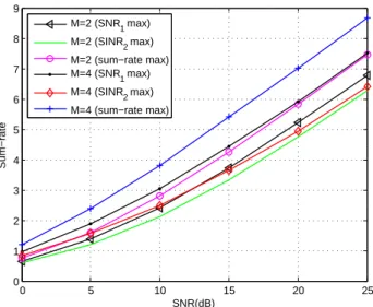
C. Sum-Rate Performance
Fig. 7 and Fig. 8 show the sum-rate performance com-parison with respect to different relay antenna numbers. The iterative technique is better than the relay beamforming design targeting either SNR1 maximization or SINR2 maximization.
And the proposed algorithm performs close to the loose sum-rate upper bound. Therefore, the proposed iterative algorithm is an efficient tool to address sum-rate maximization of the multi-antenna AF CDR system, although it is sub-optimal. Furthermore, the sum-rate gain from the multiple-antenna relay beamforming is obvious, compared to the single antenna relay transmission. With the increase of the number of an-tennas at relay, we can see a clear increase in the sum-rate performance.
0 5 10 15 20 25
0 1 2 3 4 5 6 7 8 9 SNR(dB) Sum−rate
M=2 (SNR1 max)
M=2 (SINR2 max)
M=2 (sum−rate max) M=4 (SNR1 max)
M=4 (SINR2 max)
M=4 (sum−rate max)
SINR2=hH2
En2nH2 −1h2
=
√
P h2B √
Ph2RWhRB
H
1 0
0 h2RWWHhH2R+ 1
−1 √
P h2B √
Ph2RWhRB
=(P
2|h
21|2+P)h2RWhRBhHRBWHhH2R+P|h2B|2(h2RWWHhH2R+ 1) +P2|h2B|2h2RWhR1hHR1WHhH2R Ph2RWhR1hHR1WHhH2R+ (P|h21|2+ 1)(h2RWWHhH2R+ 1)
−P
2h
2Bh∗21h2RWhR1hHRBW
HhH 2R+P
2h
21h∗2Bh2RWhRBhHR1W HhH
2R Ph2RWhR1hHR1WHhH2R+ (P|h21|2+ 1)(h2RWWHhH2R+ 1)
(7)
arg max
W
PhBRWhR1hHR1WHhHBR+hBRWWHhHBR+ 1 hBRWWHhHBR+ 1
×[1+
(P2|h
21|2+P)h2RWhRBhHRBW
HhH
2R+P|h2B|2(h2RWWHhH2R+ 1) +P
2|h
2B|2h2RWhR1hHR1W HhH
2R Ph2RWhR1hHR1WHhH2R+ (P|h21|2+ 1)(h2RWWHhH2R+ 1)
+−P
2h
2Bh∗21h2RWhR1hHRBW
HhH 2R−P
2h
21h∗2Bh2RWhRBhHR1W HhH
2R Ph2RWhR1hHR1WHh
H
2R+ (P|h21|2+ 1)(h2RWWHhH2R+ 1) ]
s.t. P(hHRBW
H
WhRB+hHR1W H
WhR1) +||W||2F =PR (8)
0 5 10 15 20 25
0 1 2 3 4 5 6 7 8 9 10
SNR(dB)
Sum−rate
M=2
M=2 Upper Bound M=4
M=4 Upper Bound M=1
Figure 8. Sum-rate performance.
V. CONCLUSIONS ANDFUTUREWORKS
We focus on the design for the relay beamforming of the AF CDR system. Relay beamforming design for sum-rate maximization is considered. We propose a low-complexity but efficient iterative algorithm to achieve the sum-rate maximiza-tion and derive the upper bound of the achievable sum-rate. Numerical results confirm that the proposed iterative design gives comparable sum-rate and performs close to the loose upper bound as well as show a obvious sum-rate increase from the usage of multiple relay antennas.
APPENDIXA PROOF OFLEMMA1
Proof:From (4) and (7), the problem (3) can be
reformu-lated in (8).In order to rewrite the optimization cost function in a simple way, the beamforming matrixWis converted into a vector form using the vectorization operation,w=vec(W). With the propertyvec(MWN) = (NT⊗M)vec(W), we can rewrite the problem in (9).
For the next step, we introduce matrixJfrom the Cholesky decomposition
P(hTRB⊗I)H(hTRB⊗I) +P(h
T
R1⊗I) H(hT
R1⊗I)+I,J H
J.
We letw˜=Jw. When applyingw=J−1w, the problem can˜
be finally reformulated in (10). We further observe that the norm ofw˜ does not influence the maximization at all. Hence, the constraint can be ignored. This transforms the problem (10) into an unconstrained maximization problem.
After some mathematical manipulations, it can be readily observed the reformulated sum-rate maximization beamform-ing design problem is in the form of
arg max
˜
w G( ˜w) = arg maxw˜
w˜HAw˜
˜
wHB ˜w ×
˜ wHCw˜
˜ wHD ˜w
where matricesA,B,C, andDare not dependent onw. This˜ completes the proof.
ACKNOWLEDGMENT
arg max
w
PwH(hT
R1⊗hBR)H(hTR1⊗hBR)w+wH(I⊗hBR)H(I⊗hBR)w+ 1 wH(
I⊗hBR)H(I⊗hBR)w+ 1
× {1+
wH(P2|h21|2+P)(hTRB⊗h2R)H(hTRB⊗h2R) +P|h2B|2(I⊗h2R)H(I⊗h2R)
w+P|h2B|2 PwH(hT
R1⊗h2R)H(hRT1⊗h2R)w+ (P|h21|2+ 1) [wH(I⊗h2R)H(I⊗h2R)w+ 1]
+ w
H
P2|h
2B|2(hTR1⊗h2R)H(hTR1⊗h2R)w PwH(hT
R1⊗h2R)H(hRT1⊗h2R)w+ (P|h21|2+ 1) [wH(I⊗h2R)H(I⊗h2R)w+ 1] +
wH
−P2h
2Bh∗21(hTRB⊗h2R)H(hTR1⊗h2R)−P2h21h∗2B(hTR1⊗h2R)H(hTRB⊗h2R)w PwH(hT
R1⊗h2R)H(hRT1⊗h2R)w+ (P|h21|2+ 1) [wH(I⊗h2R)H(I⊗h2R)w+ 1] }
s.t. wH
P(hTRB⊗I)H(hTRB⊗I) +P(h
T
R1⊗I) H(hT
R1⊗I)+I
w=PR (9)
arg max
˜
w
˜
wHnJ−H
P(hT
R1⊗hBR)H(hTR1⊗hBR) + (I⊗hBR)H(I⊗hBR)
J−1+ 1
PRI
o ˜ w
˜
wHhJ−H(
I⊗hBR)H(I⊗hBR)J−1+P1RI i
˜ w
× {1+
˜
wHnJ−H(P2|h21|2+P)M+P|h2B|2N+P2|h2B|2K−P2h2Bh∗21T−P 2h
21h∗2BTH
J−1+P|h2B|2
PR I
o ˜ w
˜
wHnJ−H
(P|h21|2+ 1)(I⊗h2R)H(I⊗h2R) +P(hTR1⊗h2R)H(hTR1⊗h2R)J−1+P|h21|
2+1
PR I
o ˜ w
}
s.t. w˜Hw˜ =PR
M= (hTRB⊗h2R)H(hTRB⊗h2R) N= (I⊗h2R)H(I⊗h2R)
K= (hTR1⊗h2R)H(hTR1⊗h2R) T= (hTRB⊗h2R)H(hTR1⊗h2R) (10)
REFERENCES
[1] G. Farhadi and N. Beaulieu, “Capacity of amplify-and-forward multi-hop relaying systems under adaptive transmission,”IEEE Trans. Com-mun., vol. 58, no. 3, pp. 758–763, Mar. 2010.
[2] Y. Zhu, P.-Y. Kam, and Y. Xin, “Differential modulation for decode-and-forward multiple relay systems,”IEEE Trans. Commun., vol. 58, no. 1, pp. 189–199, Jan. 2010.
[3] M. Uppal, Z. Liu, V. Stankovic, and Z. Xiong, “Compress-Forward Coding With BPSK Modulation for the Half-Duplex Gaussian Relay Channel,”IEEE Trans. Signal Process., vol. 57, no. 11, pp. 4467–4481, Nov. 2009.
[4] P. Popovski and H. Yomo, “Bi-directional Amplification of Throughput in a Wireless Multi-Hop Network,” inProc. IEEE VTC-Spring, May 2006.
[5] S. Katti, S. Gollakota, and D. Katabi, “Embracing Wireless Interference: Analog Network Coding,” inProc. SIGCOMM, Aug. 2007.
[6] H. Ning, C. Ling, and K. K. Leung, “Wireless Network Coding with Imperfect Overhearing,”submitted to IEEE Trans. Commun., 2010. [7] C. Thai, P. Popovski, M. Kaneko, and E. Carvalho, “Coordinated
Trans-missions to Direct and Relayed Users in Wireless Cellular Systems,” in Proc. IEEE ICC, June 2011.
[8] C. Thai and P. Popovski, “Coordinated Direct and Relay Transmission with Interference Cancelation in Wireless Systems,” IEEE Commun. Lett., vol. 15, no. 4, pp. 416–418, Apr. 2011.
[9] B. Bandemer, Q. Li, X. Lin, and A. Paulraj, “Overhearing-Based Interference Cancellation for Relay Networks,” inProc. IEEE VTC-Fall, Sep. 2009.
[10] H. Yomo and E. Carvalho, “Spectral efficiency enhancement with interference cancellation for wireless relay network,” in Proc. IEEE PIMRC, Sep. 2008.
[11] W. Chen, K. Letaief, and Z. Cao, “Network interference cancellation,” IEEE Trans. Commun., vol. 8, no. 12, pp. 5982–5999, Dec. 2009. [12] D. Tse and P. Viswanath, Fundamentals of Wireless Communication.
Cambridge University Press, 2005.
[13] N. Lee, H. J. Yang, and J. Chun, “Achievable Sum-Rate Maximizing AF Relay Beamforming Scheme in Two-Way Relay Channels,” inProc. IEEE ICC, May 2008.
[14] G. H. Golub and C. F. V. Loan, Matrix Computations. The Jokns Hopkins University Press, Third Edition, 1996.