Hybrid active Power filter for power conditioning by using Space Vector
Modulation controller
1Pathan Irufhan Khan,2Katari.Ramcharan
1P.G Student,2Asst.prof.Dept.of EEE,BVCEngineering College, Odalarevu, AP,India 1[email protected],2[email protected]
Abstract: Active power filters are widely used in power systems due to their advantages to maintain power quality. In this paper, presents a control method for hybrid active power filter using Space Vector Pulse Width Modulation (SVPWM). In the proposed control method, the Active Power Filter (APF) reference voltage vector is generated instead of the reference current, and the desired APF output voltage is generated by SVPWM. Proper controller is developed to maintain power quality with APF. The entire power system block set model of the proposed scheme has been developed in MATLAB environment. The APF based on the proposed method can eliminate harmonics, compensate reactive power and balance load asymmetry. Extensive simulation results are presented with case studies.
Key Words: Active power filters, Non-linear loads, Space Vector Modulation
1.1 Introduction
The growing use of power system, non-linear and time-varying loads has led to distortion of voltage and current waveforms and increased reactive power demand in ac mains. In this process, harmonics are induced and affected on input side of the supply as well as load side. Harmonic distortion is known to be source of several problems, such as increased power losses, excessive heating in rotating machinery, and harmonic resonances in the utility, significant interference with communication circuits, flicker and audible noise, incorrect operation of sensitive loads [1, 2]. Traditionally, LC tuned passive filters have been used to absorb harmonic currents generated by nonlinear loads. Their main advantage is high reliability and low cost. However, passive filters have several drawbacks, which may cause harmonic interaction with the utility problems with the utility system, in the presence of stiff utility sharp tuning of the LC filter is required and may not meet the specified harmonic current limits [3, 4]. This provides the motivation for investigation of an active filter topology, which is practically viable, cost effective and can meet the recommended standard for high power nonlinear loads. For high-power applications, the active filters are not cost effective due to their large rating and high switching-frequency requirement of the Pulse Width Modulation (PWM) inverter.
1.2 Proposed Work
In this paper, a new controller is proposed to maintain good power quality. Among the various topologies the shunt active filter based on Voltage Source Inverter (VSI) is the most common one because of its efficiency [5]. Proposed controller is tested by Mat lab simulation. The performance of active filter depends on the adoptive control approaches. There are two major parts of an active power filter controller.
The first is that determines the reference current of APF and maintains a stable DC bus voltage. Various current detection methods, such as instantaneous reactive power theory, synchronous reference frame method, supplying current regulation and etc., are presented.
An alternative control method for shunt APF’s is
proposed in this project [6]. The proposed method differs from previously discussed approaches in the following ways: a) To generate APF reference voltage vector instead of reference current; b) to generate desired APF output voltage by Space Vector Pulse Width Modulation (SVPWM) [7, 8] based on generated reference voltage. Therefore, the proposed method is simple and easy to carryout. This project discussed the basic principle of this method in detail and proved its validity by simulation results.
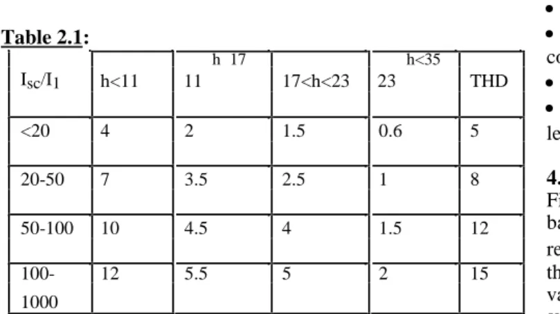
In order to maintain good power quality, various international agencies recommended limits of harmonic current injecting into the utility according to IEEE-519 standards the limits on the magnitude of harmonic currents and harmonic voltage distortion at various frequency are specified given in Tables 2.1 and 2.2.
The amount of distortion in the voltage or current waveform is quantified by means of an index called THD, the THD in current is defined as
%
THD =100×
Isn/Is1 2
n1
Table 2.1: Isc/I1 h<11
≤h≤17
17<h<23
≤h<35 THD
11 23
<20 4 2 1.5 0.6 5
20-50 7 3.5 2.5 1 8
50-100 10 4.5 4 1.5 12
100- 12 5.5 5 2 15
1000
Where Isc is the main short circuit current at the point of common coupling. I1 is the maximum fundamental frequency load current.
Table 2.2
HARMONIC VOLTAGE LIMITS FOR POWER PRODUCERS:
2.3-69 kv 69-138 kv
Max.for 3.0 1.5
induced harmonics
THD 5.0 2.5
The table 2.2 lists the quality of the voltage that power producer is required to furnish a user. It is based on the voltage level at which the user is supplied.
4.3 THEORY OF SVPWM TECHNIQUE
SVPWM technique was originally developed as a vector approach to pulse–width modulation for three -phase inverters. The SVPWM method is frequently used in vector controlled applications. In vector controlled applications this technique is used for reference voltage generation when current control is exercised. It is a more sophisticated, advanced, computation intensive technique for generating sine wave that provides ahigher voltage with lower total harmonic distortion and is possibly the best among all the pulse width modulation techniques. It confines space vectors to be applied according to the region where the output voltage vector is located. Because of its superior performance characteristics, it is been finding wide spread applications in recent years. The main aim of any modulation technique is to obtain variable output voltage having a maximum fundamental component with minimum harmonics. Many PWM techniques have been developed for letting the inverters to posses various desired output characteristics to achieve the wide linear modulation range, less switching losses, lower harmonic distortion. The SVPWM technique is more popular than conventional technique because of its excellent features.
More efficient use of DC supply voltage.
15% more output voltage then conventional modulation.
Lower total Harmonic distortion
Prevent un-necessary switching hence less commutation losses
4.4 PRINCIPLE OF SVPWM
Firstly model of a three-phase inverter is presented on the basis of space vector representation. The three-phase VSI is reproduced in Fig.3.1. S1to S6 are the six power switches that shape the output, which are controlled by the switching
Therefore, the on and off states of the upper switches S1, S3, S5can be used to determine the output voltage.
Fig 4.6 Power circuit of a three-phase VSI(4.2)
As illustrated in Fig.4.6, there are eight possible combinations of on and off patterns for the three upper power switches. The on and off states of the lower power devices are opposite to the upper one and so are easily
determined once the states of the upper power transistors are determined. According to equations (4.1) and (4.2), the eight switching vectors, output line to neutral voltage (phase voltage), and output line-to -line voltages in terms of DC-link Vdc, are given in Table 4.1 and Fig.4.2 shows the eight inverter voltage vectors (V0to V7).
Table 4.1 Switching vectors, phase voltages and output line to line voltages
SVPWM refers to a special switching sequence of the upper power switches of a three-phase power inverter. It has been shown to generate less harmonic distortion in the output voltages and/or currents applied to the phases of a power system and to provide more efficient use of supply voltage compared with other modulation technique.
5.3 Compensation Principle
In the Fig.5.2, vfa,1and vfa,hdenote the output fundamental and harmonic voltages of the inverter, respectively. These voltage sources are connected to a supply source ( vsa ) in parallel via a link inductor Lfand capacitor Cf.The supply current isais forced to be free of harmonics by appropriate voltages from the APF and the harmonic current emitted from the load is then automatically compensated.
It is known from Fig.5.2, that only fundamental component is taken into account, the voltages of the ac supply and the APF exist the following relationship in the steady state
s
L
f
d
I
f 1
1
f 1
dt
f 1V
C
I
V
(5.3)f
dt
where
V
sis the supply voltage,I
f 1is the fundamental current of APF,V
f 1 is the fundamental voltage of APF, and above variables are expressed in form of space vector. The APF is joined into the network through the inductor Lf and Cf. The function of these is to filter higher harmonics nearly switching frequency in the current and to link two ac voltage sources of the inverter and the network. So the required inductance and capacitance can just adopt a small value. Then the total reactance caused by inductor and capacitor for the frequency of 50Hz, and the fundamental voltages across the link inductors and capacitors are also very small, especially compared with the mains voltages. Thus the effect of the voltage of the link inductor and capacitor is neglected. So the following simplified voltage balanced equation can be obtained from equation (5.3).V
s
V
f 1 (5.4)The control object of APF is to make the supply current sinusoidal and in phase with the supply voltage. Thus the nonlinear load and the active power filter equals to a pure resistance load R s, and the supply voltage and the supply
current satisfy the following equation:
s
R
s
I
sV
(5.5)where
I
s
2
3
i
saa
0
i
sba
1
i
sca
2
I
sd
jI
sq
I
s
i. Then the relationship between Is and the supply voltage amplitude VsisV
s
R
sI
s (5.6)Substituting (5.5), (5.6) into (5.4) results in
V
s
sV
f 1
I
(5.7)I
sFig.5.3 Control block diagram of proposed algorithm
The Fig.5.3 shows the block diagram of active filter controller implemented for reducing the harmonics with hybrid active filter system. In each switching cycle, the controller samples the supply currents isa,iscand the supply current iscis calculated with the equation of -(isa+isc), as the summation of three supply current is equal to zero. These three-phase supply currents are measured and transformed into synchronous reference frame (d-q axis). The fundamental component of the supply current is transformed into dc quantities in the (d-q) axis and the supply currentamplitudeIsgenerated by the PI controller with Vdc and Vref, the reference value of the dc bus voltage. The obtained d-q axis components generate voltage command signal. By using Fourier magnitude block, voltage magnitude and angle is calculated from the obtained signal. These values are fed to the developed code and compared with the repeating sequence. Then the time durations T1, T2 and T0, the on-time of V1, V2 and V0 are calculated as already explained in chapter 3. The generated switching actions are applied to the APF and power balancing of the filter takes place.
6.1 INTRODUCTION
The developed control method for three-phase shunt APF is simulated in MATLAB/Simulink. Firstly, the three -phase supply currents are sensed and transformed into synchronous reference frame (d-q) axis. The fundamental component of the supply current is transformed into dc quantities in the (d-q) axis and the supply current amplitude Isgenerated by the PI controller. The obtained d-q axis components generate voltage command signal. By using Fourier magnitude block, voltage magnitude and angle is
System parameters Values of parameters
Supply system 230 V (rms), 50 Hz, three-phase supply
Balanced linear load Zl= 75 + j 62.83Ω
Unbalanced linear Zla= 75 + j 31.42Ω, Zlb= 100 + j 23.56
load Ω,
Zlc=85+ j 31.42Ω
Non-linear load with R=1000Ω
resistance
APF Cdc=1000µf, Vref = 750V, Cf= 24µf,
Lf= 30 mH
calculated from the obtained signal. These values are fed to the developed code and generated switching actions are applied to the APF. Thus, power balancing of the filter takes place. Further, the performance with different type of loads is presented.
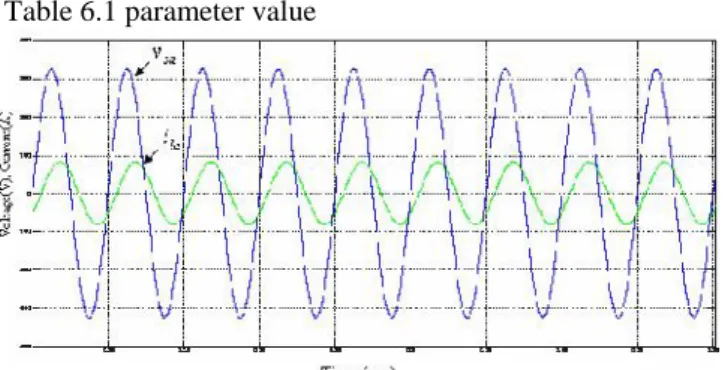
The complete simulation model of APF with different type of loads is shown in Fig.6.1 and Fig.6.2. For an input supply voltage of 230V (rms) and switching frequency of 5kHz, the simulation results before and after power
balancing are shown.
Table 6.1 parameter value
The phase-A supply voltage and load current
Three-phase load current
(a) The phase-A load current harmonic spectrum
6.3 CONCLUSION
currents.
In this project, a control methodology for the APF using SVPWM is proposed. This method requires few sensors, simple in algorithm and able to compensate harmonics and unbalanced loads. The performance of APF with this method is done in MATLAB/Simulink. The algorithm will be able to reduce the complexity of the control circuitry. The harmonic spectrum under non-linear load conditions shows that reduction of harmonics is better. Under unbalanced linear load, the magnitude of three-phase source currents are made equal and also with balanced linear load the voltage and current are made in phase with each other. The simulation study of two level inverter is carried out using SVPWM because of its better utilization of dc bus voltage more efficiently and generates less harmonic distortion in three-phase voltage source inverter. This SVPWM control methodology can be used with series APF to compensate power quality distortions.
REFERENCES:
[1] EI-Habrouk. M, Darwish. M. K, Mehta. P, “Active
power filters-A review,” Proc. IEE-Elec. Power Applicat., vol. 147, no. 5, Sept. 2000, pp. 403-413. [2] Akagi, H., “New trends in active filters for power
conditioning,” IEEE Trans. on Industry applications,
vol. 32, No. 6, Nov-Dec, 1996, pp. 1312-1322.
[3] Singh.B, Al-Haddad.K, Chandra.A, “Review of active filters for power quality improvement,” IEEE Trans.
Ind. Electron., vol. 46, No. 5, Oct, 1999, pp. 960-971. [4] Ozdemir.E, Murat Kale, SuleOzdemir, “Active power
filters for power compensation under non-ideal mains
voltages,” IEEE Trans. on Industry applications, vol.12, 20-24 Aug, 2003, pp.112-118.
[5] Dan.S.G, Benjamin.D.D, Magureanu.R,
Asimionoaei.L, Teodorescu.R, Blaabjerg.F, “Control
strategies of active filters in the context of power
conditioning,” IEEE Trans. on Ind.
applications,vol.25,11-14 Sept-2005, pp.10-20
[6] Wang Jianze, PengFenghua, Wu Quitao, JiYanchao,
“A novel control method for shunt active power filters using svpwm,” IEEE Trans. on Industry applications,
vol.1, 3-7 Oct, 2004, pp.134-139.
[7] Atif Iqbal, Lamine.A, Imtiaz.Ashraf, Mohibullah,
“Matlab model of space vector pwm for three-phase
voltage source inverter,” universities power engineering conference, 2006, UPEC’06, proceedings
of the 41st international volume 3, 6-8 Sept. 2006, pages:1096-1100.
[8] Rathnakumar.D, LakshmanaPerumal, Srinivasan.T, “A new software implementation of space vector pwm,”
IEEE Trans. Power Electron., vol.14,8-10 April 2005, pp.131-136.