Introduction
As mobile communications evolve, mobile end-users will be offered wideband media capabilities. The associated multi-media streams require that the networks should be more flexible than present-day networks—which are based on
time-division multiplexing (TDM)—at provid-ing bandwidth on demand. The networks must thus evolve toward cell- and packet-based technologies. As the transport tech-nology evolves, the network paradigm also changes. The vertical networks—with a sep-arate network dedicated to each individual application—will be replaced by a horizon-tally layered network architecture. Media gateways will play a fundamental role in the evolution toward the new network archi-tecture, mediating at the crossing point be-tween existing and new transmission tech-nologies and network types.
Ericsson is working actively with rele-vant standardization bodies and other fora (such as the ITU, ETSI, MSF, 3GPP and IETF) to bring about this network archi-tecture and to ensure open and standardized interfaces. In the universal mobile telecom-munications system (UMTS), the horizon-tally layered architecture1divides the
net-work into an • application layer;
• network control layer; and • common connectivity layer.
In the network control layer (Figure 1), the MSC server controls circuit-mode services and the serving GPRS support node (SGSN) server controls packet-mode services. In the connectivity layer, the media gateway uses open interfaces to connect to different types of node in the core network and external net-works. The media gateway control interface (H.248) facilitates a separation of network control and connectivity layers. The inter-face to the UMTS terrestrial radio access net-work (UTRAN) is called Iu. In Figure 1, a voice call between the UTRAN and PSTN is interconnected by two media gateways. Media gateway A switches ATM or routes IP traffic. It also provides interworking functions between ATM and IP. The MSC server and gateway MSC/transit switching center (TSC) server control media gateway B, by means of H.248 control paths. Media gateway Bprocesses the media stream and provides interfaces to the PSTN. In this ap-proach, the voice coder is only inserted when needed at the edge of the core network. This gives improved voice quality and facilitates more efficient use of bandwidth in the core network.
In the connectivity layer, the Gn inter-face handles packet-mode traffic between the media gateway and the gateway GPRS support node (GGSN).2The SGSN server
controls the media gateway by means of H.248.
Media gateway for mobile networks
Magnus Fyrö, Kai Heikkinen, Lars-Göran Petersen, and Patrik Wiss
The telecommunications community is migrating toward a new network architecture based on horizontal layers. Call control and connectivity, which have traditionally been bundled in telecommunication networks, are being separated into different layers. The connectivity layer is based pri-marily on asynchronous transfer mode (ATM) and Internet protocol (IP) transmission. Access networks and the core network are parts of the con-nectivity layer. The concon-nectivity layer provides interfaces to legacy net-works, such as the public switched telephone network (PSTN). The lay-ered architecture is being deployed in third-generation mobile
networks—that is, the universal mobile telecommunication system (UMTS). Ericsson has taken an active role in promoting this new architec-ture in relevant standardization bodies.
Media gateways (MGW) have been introduced to bridge between differ-ent transmission technologies and to add service to end-user connec-tions. Smooth step-by-step migration toward the new network architec-ture is achieved by splitting the mobile services switching center (MSC) and the serving GPRS support node (SGSN) into a media gateway and servers.
The authors describe the role of the media gateway in third-generation mobile networks, and present Ericsson’s new media gateway product, which is based on the Cello packet platform.
MSC server HSS MGW MGW GGSN UTRAN Core network connectivity layer (QoS-enabled ATM or IP) MAP MAP Call control Call control H.248 H.248 H.248 GTP-C lu Gn ATM Call contr ol Q.1901 (BICC) GMSC/ TSC-server PSTN/ISDN/ PLMN Internet/ intranet SGSN server Figure 1
Quality of service (QoS) plays a central role in the new networks: it is a means of providing end-users with agreeable service and is essential for network management. The media gateway facilitates quality of ser-vice by supporting ATM and IP traffic en-gineering through a combination of • ATM traffic management—for ATM;
and
• multiprotocol label switching (MPLS) and differentiated services (DiffServ)— for IP.
Migration toward the new
network
When described in terms of the new net-work architecture, Ericsson’s AXE systems have traditionally comprised both the net-work control and connectivity layers in the same node. To migrate toward the new ar-chitecture, the AXE MSC is first divided in-ternally, creating an MSC server and a media gateway. The node can then be physically split (Figure 2): the MSC server is based on
3GPP Third-generation Partnership Project AMR Adaptive multirate
API Application program interface ATM Asynchronous transfer mode BICC Bearer-independent call control CDMA Code-division multiple access CORBA Common object request broker
architecture
DSP Digital signal processor DTMF Dual-tone multifrequency ET Exchange terminal
ETSI European Telecommunication Standards Institute
FTP File transfer protocol GGSN Gateway GPRS support node GPB General-purpose board GPRS General packet radio service GSM Global system for mobile
communication
GTP Gateway tunneling protocol GTP-C GTP control
GTP-U GTP user plane
GUI Graphical user interface HSS Home subscriber server HTML Hypertext markup language HTTP Hypertext transfer protocol IETF Internet Engineering Task Force IIOP Internet inter-object request broker
protocol IP Internet protocol IPv4 IP version 4 IPv6 IP version 6
IRP Integrated reference point ISDN Integrated services digital network ITU International Telecommunication
Union
L2TP Layer 2 tunneling protocol LER Label edge router MGW Media gateway
MIB Management information base MPC Multiparty call
MPLS Multiprotocol label switching MSB Media stream board
MSC Mobile services switching center
MSF Multiservice Switching Forum MTP Message transfer part PDP Packet data protocol QoS Quality of service RNC Radio network controller RTP Real-time transport protocol SCCP Signaling connection control part SCTP Stream control transport protocol SDH Synchronous digital hierarchy SGSN Serving GPRS support node SNMP Simple network management
protocol
SPB Special-purpose board SS7 Signaling system no. 7 STP Signal transfer point TDM Time-division multiplexing TSC Transit switching center TTC Telecommunication Technology
Committee
UDP User datagram protocol UMTS Universal mobile
telecommunications system
BOX A, TERMS AND ABBREVIATIONS
SGSN MSC MSC server Media gateway
Server - control layer
Media gateway - connectivity layer Step 1 Step 2 SGSN MSC SGSN server Figure 2
Ericsson server-gateway split migration path.
AXE and the media gateway is based on the Cello packet platform (CPP).3
A similar migration takes place in the GPRS network. The current SGSN is split into an internal server and a media gateway. These can then be physically split—all con-nectivity network functionality is ported to the media gateway. The media gateway is thus common to circuit-mode and packet-mode core networks. The media gateway will also be introduced into GSM core networks.
Media gateway
The media gateway comprises several func-tional entities. The physical node is divid-ed into several virtual mdivid-edia gateways. A specific server controls each virtual media gateway, which shares resource components that are visible from the resource component database. However, resource components can also be preconfigured, by identity and type, for any virtual media gateway. Special care has been taken to provide clean and ro-bust interfaces between the virtual media gateway, resource component database, and resource components. This modular ap-proach facilitates smooth upgrades on differ-ent sides (Figure 3).
When an H.248 message arrives from the server, it is broken down and delivered to the virtual media gateway to which it be-longs. The connection handler sets up the state logic for the connection and allocates available resource components according to the resource component database. These components are interconnected to process a stream and carry it through the media gate-way from one network to another.
Resource components are composed of media framing components and media stream components. Media framing compo-nents terminate different protocol layers— for example, IP, user datagram protocol (UDP) and real-time transport protocol (RTP). The media stream components process voice and data calls. Resource com-ponents can be seen as versatile building blocks in the functional architecture. They also extract relevant data on performance and fault management according to the re-quirements in H.248 and according to the corresponding managed objects in the man-aged object model. The resource compo-nents interconnect to the Cello packet plat-form by means of application program in-terfaces (API).
The media gateway is designed as an ap-plication on the Cello packet platform, MGW node Virtual MGW MGW application SGWapplication Resource component database Resource components Media framing component Switch fabric CPP API API Embedded real-time router Physical interfaces ATM/AAL2 switch Operation and maintenance Media stream component H.248 message handler Connection handler Figure 3
Functional architecture of the media gateway.
Resource component
database
ATM AAL2
Media framing Media stream Media framing Resource components
luFH coderVoice
Connection handler (one connection chain)
Echo canceller RTP UDP IP Logical view Connection chain Figure 4 Connection model.
which is a fully redundant telecom platform that can be used for several different prod-ucts. Its robust, real-time control system and efficient cell transport system guaran-tee cost-effective applications that support time-division multiplexing, ATM and IP transmission. The execution platform of the Cello packet platform offers a scalable clus-ter of inclus-tercommunicating processors, a tributed, real-time operating system, a dis-tributed real-time database, and O&M sup-port. Internally, the Cello packet platform embraces ATM (including ATM adaptation layer 2, AAL2) switching capabilities. A cell-switching fabric allows functionality to be distributed across boards and subracks.
A real-time router4, which is embedded
in the media gateway, provides distributed forwarding at wireline speeds to all inter-faces. The real-time router
• handles IPv4, IPv6, header compression, IP security protocol (IPsec), and differen-tiated services (DiffServ);
• provides MPLS edge functionality, in-cluding traffic engineering and protec-tion;
• provides advanced firewall filtering and classification; and
• supports virtual private networks (VPN). Figure 4 shows a simplified view of the con-nection model. The concon-nection handler, which keeps a logical view of the connection
chains, interconnects resource components by means of the switch fabric. The resource components can thus have any physical lo-cation in the node. Figure 4 shows a con-nection chain with compressed voice over ATM/AAL2 that is converted to uncom-pressed voice over IP (VoIP). In this exam-ple, voice coding and echo-cancellation ser-vices are performed on the voice stream.
By inserting different kinds of media framing and media stream components, it is possible to set up processing of virtually any media stream on demand. Only a small set of component types is needed, and it is not necessary to prepare in advance for all forthcoming combinations of functionality in a connection chain.
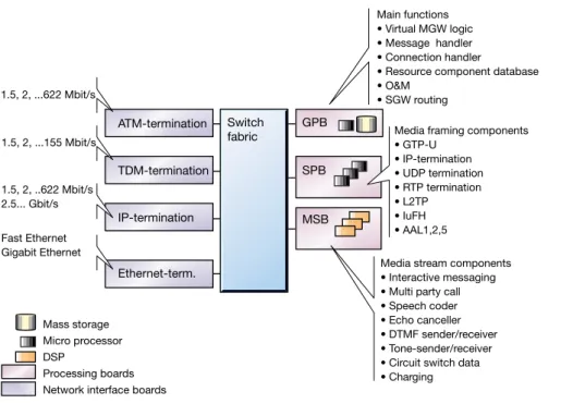
The media gateway comprises several physical interfaces ranging from 1.5 to 155 Mbit/s. Future releases will include 622 Mbit/s and 2.5 Gbit/s interfaces and Giga-bit Ethernet. The interface to the switch fab-ric is not dependent on rate or technology. Operators can upgrade the switch fabric, in-terfaces, or processor boards without dis-turbing traffic. Three kinds of processor board are available (Figure 5):
• The general-purpose board (GPB) targets processes that execute on the distributed processor cluster.
• The special-purpose board (SPB) is a workhorse for protocol termination. The
Main functions • Virtual MGW logic • Message handler • Connection handler
• Resource component database • O&M
• SGW routing
Media framing components • GTP-U • IP-termination • UDP termination • RTP termination • L2TP • IuFH • AAL1,2,5
Media stream components • Interactive messaging • Multi party call • Speech coder • Echo canceller • DTMF sender/receiver • Tone-sender/receiver • Circuit switch data • Charging 1.5, 2, ...622 Mbit/s 1.5, 2, ...155 Mbit/s 1.5, 2, ..622 Mbit/s 2.5... Gbit/s Fast Ethernet Gigabit Ethernet Mass storage Micro processor DSP Processing boards Network interface boards
ATM-termination Switch GPB fabric SPB MSB TDM-termination IP-termination Ethernet-term. Figure 5
Hardware view and functional example of distribution.
board, which comprises several standard microprocessors, is meant to handle most of the media framing components. • The media stream board (MSB) is a
work-horse for processing media streams (Fig-ure 6). It is composed of several standard digital signal processors (DSP). Nearly all media stream components are processed on this board. To allow efficient and flex-ible resource handling, all media stream components in the media gateway are thought of as belonging to a common pool.
Resource components
The resource components can be allocated to any of the processor boards. However, for optimum performance, some board types
have been developed for use with specific components (Figure 5). The resource com-ponents can be allocated in needed numbers and type relative to the board’s total pro-cessing capacity. The concept also allows for future hardware acceleration—that is, some resource components can be implemented in dedicated hardware to further increase ca-pacity and reduce footprint. Hardware sup-port for the resource components that ter-minate ATM, AAL2, IP and TDM is pro-vided on associated network interface boards.
Media framing components
The main task of the media framing com-ponents (Box B) is to convert protocols be-tween different transmission networks and to adapt them to the media stream compo-nents (Box C).
The media framing components also sup-port SGSN functionality, handling user data traffic between the radio network controller (RNC) and the GGSN in the GPRS network by interconnecting two gateway tunneling protocol (GTP) media framing components. The GTP tunnels are thus adapted in the media gateway between the Iuand Gn in-terfaces (Figure 1). Using this same mecha-nism, it is easy to process the streams by in-serting a media stream component. For ex-ample, with the outlined architecture, the GPRS network can easily be enhanced with real-time media streams.
Examples of media framing components
• Asynchronous transfer mode (ATM). • ATM adaptation layer 1 (AAL1). • ATM adaptation layer 2 (AAL2). • ATM adaptation layer 5 (AAL5). • Internet protocol (IP).
• User datagram protocol (UDP). • Real-time transport protocol (RTP). • Layer 2 tunneling protocol (L2TP). • Multiprotocol label switching-label edge
router (MPLS-LER).
• Gateway tunneling protocol (GTP). • Time-division multiplexing (TDM).
BOX B, MEDIA FRAMING COMPONENTS
Figure 6
Signaling gateway
In many network configurations, media streams and signaling share the same phys-ical lines to the media gateway. A signaling gateway function is needed to convey the signaling messages across different trans-port domains. For example, call control mes-sages must be exchanged for a call that spans an IP-based core network and the PSTN. These messages are set up between the servers but the call is transmitted through the media gateway node. To reduce the foot-print, the signaling gateway application— which provides signaling interworking be-tween IP, ATM, and TDM networks—has been co-located in the media gateway node. The signaling gateway application also con-tains signal transfer point (STP) functional-ity, in order to relay signaling system no. 7 (SS7) messages over the message transfer part (MTP3 and MTP3b) in TDM and ATM networks as well as over the stream control transport protocol (SCTP) in IP networks.
Operation and
maintenance
The media gateway is managed by a Web-based thin-client application that can be run from a standard Web browser and Java vir-tual machine on any computer, locally or re-motely. The thin-client application displays a graphical presentation of the management application but does not store data on the node. The client communicates with the media gateway using the hypertext transfer protocol (HTTP), Internet inter-ORB pro-tocol (IIOP), file transfer propro-tocol (FTP), Telnet, and the simple network manage-ment protocol (SNMP). The connection be-tween the media gateway and the thin-client can be
• local—over an Ethernet cable; or • remote—using a secure intranet. Dedicated management applications are embedded in the media gateway—that is, it contains all the software it needs to man-age the node. These applications (written in Java) typically use a common object request broker architecture (CORBA) or IIOP in-terface to manipulate the management data of the node.
The graphical user interface (GUI) has the same look and feel as all other network ele-ment interfaces in Ericsson’s third-generation core network and radio access network. Online multilanguage HTML documentation—which provides Help,
Examples of media stream components
• Voice coder—the adaptive multirate (AMR) voice codec is the default voice coding/decoding algorithm for UMTS. All modes of the AMR voice codec are sup-ported. This allows operators to choose the subset of voice codecs they want to use in their networks.
• Echo canceller—echo cancellers
– attenuate echo generated from the con-version between four-wire and two-wire transmission in the PSTN; and – reduce mobile crosstalk.
• Circuit-switched data—the circuit-switched data application provides modem function-ality to the PSTN and ISDN.
• Multiparty call—support for conversations between more than two parties.
• Tone sender/receiver—the tone sender/ receiver provides tones to be sent to and received from end-users.
• DTMF sender/receiver—the DTMF sender/receiver sends DTMF tones to the far end of the connection as requested by a mobile station. It also receives DTMF tones—for example, tones that are to be used with the interactive messaging appli-cation.
• Interactive messaging—the interactive mes-saging application provides subscribers with informative messages on special conditions in the network or conditions that pertain to the service in use.
• Charging—the charging function supports the generation of volume-based charging information for GPRS services.
BOX C, MEDIA STREAM COMPONENTS
The Cello packet platform (CPP) is a new plat-form from Ericsson that primarily targets node applications in the second- and third-generation access and core networks. It fea-tures a modular design that allows applications to scale from small base stations up to very large network nodes, such as a radio network controller or media gateway. The CPP allows different applications to be co-located in the same network node. Current applications on the CPP include
• UTRAN radio network controller; • UTRAN radio base stations;
• GERAN (GSM EDGE radio access network) real-time routers;
• cdma2000 base station controllers; • cdma2000 radio base stations; and • media gateways.
search functions, and interactive support for task-oriented operations—is integrated into the media gateway. This guarantees that the information is always consistent with the software release.
The media gateway supports integrated reference points (IRP). These recommenda-tions from the 3GPP provide interoperabil-ity between managed network elements, such as the media gateway, and multiple-technology or multivendor management
systems. An IRP is an information model that defines the interface between a network element and the network management sys-tems.
Products
The media gateway can be configured to meet the needs of different operators. To fa-cilitate installation, it comes in a limited number of preconfigured subracks. Re-source components can be active by default or they can be activated gradually by means of software keys. “Hot-swapping” applies to all boards, and new types of resource com-ponent can be downloaded and put into ser-vice without disturbing traffic. Additional subracks can be introduced to upgrade ca-pacity as traffic increases. Before delivery, the subracks are fully tested and configured at the factory.
Main subrack
The main subrack has internal links to the other subracks. It also terminates high-speed physical interfaces and contains cen-tral processing functions.
Interface extension subrack
The interface extension subrack contains high-speed interfaces to handle traffic in large media gateway nodes.
H.248 is a new protocol whose role is to con-trol media gateways from servers. The proto-col has been developed by the International Telecommunication Union (ITU) and Internet Engineering Task Force (IETF).7, 8 H.248
defines a connection model, which is a central concept for describing the logical entities with-in the media gateway that can be controlled by the server. Thanks to this model, different transmission media can coexist, and media streams can be processed, in the connection. H.248 allows an authenticated server to estab-lish, move, modify, remove, and obtain events that have been reported on a connection or group of connections. A server can audit the media gateway to determine the extent of its capabilities. H.248 is a framework protocol— that is, new capabilities can be added by means of packages and profiles.
BOX E, H.248 Circuit-switched services subrack (high-speed) Circuit-switched services subrack (high-speed) Main subrack Circuit-switched services subrack (high-speed) Circuit-switched services subrack (high-speed) Circuit-switched services subrack (high-speed) Interface extension subrack Connection field
Connection field Connection field Packet-switched services subrack
Figure 7
Circuit subrack with high-speed interfaces
The circuit subrack contains high-speed in-terfaces and a corresponding number of media stream boards to handle the traffic on the interface boards.
Circuit subrack with low-speed interfaces
The circuit subrack contains low-speed in-terfaces and a corresponding number of media stream boards to handle the traffic on the interface boards.
Packet subrack with forwarding engine interfaces
The packet subrack contains wireline-speed forwarding engines and special-purpose boards for terminating GPRS IP traffic.
Conclusion
Media gateways play an important role in the evolution toward the new, horizontally lay-ered network architecture. The media
gate-ways are positioned in the connectivity layer at the crossing point between different net-works. They are fully controlled from servers via the H.248 protocol. In the connectivity layer, operators can select the transmission technology that best suits their needs— ATM, IP or TDM. By introducing MSC and SGSN servers that work together with the media gateways, operators can migrate their networks toward the new architecture.
The media gateway is built on the Cello packet platform. This platform is also used in several other network nodes, such as base stations, the radio network controller, and real-time routers. The media gateway has also been designed for use in all-IP networks that support real-time voice over IP (VoIP). It contains an embedded real-time router and an ATM/AAL2 switch with extensive support for quality of service and traffic en-gineering. The core of the media gateway architecture is flexible. This means that only the network interface boards are specific to a given transmission technology—current and emerging.
1 Dahlin, S. and Örnulf, E.: Network evolution the Ericsson way. Ericsson Review Vol. 76(1999):4, pp. 174-181.
2 Ekeroth, L. and Hedström, P-M.: GPRS sup-port nodes. Ericsson Review Vol. 77(2000):3, pp. 156-169.
3 Reinius, J.: Cello – An ATM transport and control platform. Ericsson Review Vol. 76(1999):2, pp. 48-55.
4 Börje, J., Lund, H-Å. and Wirkestrand, A.: Real-time routers for wireless networks. Ericsson Review, Vol. 76(1999): 4, pp. 190-197.
5 Witzel, A.: Control servers in core network. Ericsson Review Vol. 77(2000): 4, pp. 234-243.
6 Granbohm, H. and Wiklund, J.: GPRS –Gen-eral packet radio services. Ericsson Review Vol. 76(1999):2, pp. 82-88.
7 Recommendation H.248, ITU 8 Megaco Protocol, RFC 2885