Full length article
AGC of a multi-area power system under deregulated environment
using redox
fl
ow batteries and interline power
fl
ow controller
Tulasichandra Sekhar Gorripotu, Rabindra Kumar Sahu
*, Sidhartha Panda
Department of Electrical Engineering, Veer Surendra Sai University of Technology (VSSUT), Burla 768018, Odisha, India
a r t i c l e i n f o
Article history:Received 20 January 2015 Received in revised form 25 March 2015 Accepted 7 April 2015 Available online 15 May 2015 Keywords:
Automatic generation control (AGC) Generation rate constraint (GRC) Interline powerflow controller (IPFC) Redoxflow batteries (RFB)
Differential evolution (DE) Sensitivity analysis
a b s t r a c t
In this paper, Proportional Integral Derivative with Filter (PIDF) is proposed for Automatic Generation Control (AGC) of a multi-area power system in deregulated environment. Initially, a two area four units thermal system without any physical constraints is considered and the gains of the PIDF controller are optimized employing Differential Evolution (DE) algorithm using ITAE criterion. The superiority of proposed DE optimized PIDF controller over Fuzzy Logic controller is demonstrated. Then, to further improve the system performance, an Interline Power Flow Controller (IPFC) is placed in the tie-line and Redox Flow Batteries (RFB) is considered in the first area and the controller parameters are tuned. Additionally, to get an accurate insight of the AGC problem, important physical constraints such as Time Delay (TD) and Generation Rate Constraints (GRC) are considered and the controller parameters are retuned. The performance of proposed controller is evaluated under different operating conditions that take place in a deregulated power market. Further, the proposed approach is extended to a two area six units hydro thermal system. Finally, sensitivity analysis is performed by varying the system parameters and operating load conditions from their nominal values.
©2015 Karabuk University. Production and hosting by Elsevier B.V. This is an open access article under the CC BY-NC-ND license (http://creativecommons.org/licenses/by-nc-nd/4.0/).
1. Introduction
Automatic Generation Control (AGC) is one of the important control problems in an interconnected power system design and
operation. AGC is becoming more significant today due to the
increasing size, changing structure, emerging renewable energy
sources, new uncertainties, environmental constraints and
complexity of power systems[1e3]. In a conventional power sys-tem configuration, the generation, transmission and distribution is owned by a sole entity called a Vertically Integrated Utility (VIU), which supplies power to the clients at regulated rates. In an open energy market, Generating Companies (GENCOs) may or may not participate in the AGC task as they are independent power utilities. On the other hand, Distribution Companies (DISCOs) may contract with GENCOs or Independent Power Producers (IPPs) for the transaction of power in different areas [4]. Thus, in deregulated environment, control is greatly decentralized and Independent
System Operators (ISOs) are responsible for maintaining the system frequency and tie-line powerflows.
The researchers in the world over are trying to propose several strategies for AGC of power systems under deregulated environ-ment in order to maintain the system frequency and tie-lineflow at their scheduled values during normal operation and also during
small perturbations. Donde et al. [5] have demonstrated the
concept of restructured power system and DISCO Participation
Matrix (DPM). Chidambaram et al.[6]have proposed AGC strategy
for a two-area multi-units power system under deregulated envi-ronment in presence of Redox Flow Batteries (RFB) and Interline
Power Flow Controller (IPFC). Recently, Parmar et al. [7] have
studied the multi-source power generation in deregulated power environment using optimal output feedback controller. However, in the above literature the effect of physical constraints such as Time delay (TD) and Generation Rate Constraint (GRC) are not examined which needs further comprehensive study.
Flexible AC Transmission Systems (FACTS) controllers[8]play
a crucial role to control the power flow in an interconnected
power system. Several studies have explored the potential of using FACTS devices for better power system control since it provides more flexibility. Unified Power Flow Controller (UPFC) and Interline Power Flow Controller (IPFC) are among the most
*Corresponding author. Tel.:þ91 9439702316. E-mail address:[email protected](R.K. Sahu). Peer review under responsibility of Karabuk University.
H O S T E D BY Contents lists available atScienceDirect
Engineering Science and Technology,
an International Journal
j o u rn a l h o m e p a g e : h t t p : / / w w w . e l s e v i e r . c o m / l o c a t e / j e s t c h
http://dx.doi.org/10.1016/j.jestch.2015.04.002
2215-0986/©2015 Karabuk University. Production and hosting by Elsevier B.V. This is an open access article under the CC BY-NC-ND license (http://creativecommons.org/ licenses/by-nc-nd/4.0/).
versatile FACTS controllers which are connected in series with the transmission line or in tie-lines respectively to control the power flow[9,10]. Both UPFC and IPFC need at least two converters. It is
observed from literature that, UPFC is employed to power flow
control of a single transmission line whereas the IPFC is can
provide power flow control for multi-line transmission system.
Therefore, IPFC is attractive for compensating multi-line systems from economical point of view. IPFC can compensate each transmission line separately or concurrently so that the power optimization of the overall system can be obtained in the form of appropriate power transfer from over-loaded lines to under-loaded lines [6]. In view of the above, an IPFC is considered in the present paper.
Balancing of power supply and demand is always a complex process particularly at peak loads. As a result, there may be serious concerns about reliable operation of power system. So, it is necessary to include Battery Energy Storage (BES) systems especially in the present deregulated scenario to improve the automatic generation control problem[11e18]. There are several types of battery energy storage systems used in power system applications such as lead acid batteries, flooded type batteries, Valve regulated (VRLA) type batteries, Sodium sulphur (NaS) batteries, Lithium ion (Li ion), Metal air and Redox Flow Bat-teries (RFB). Among all the batBat-teries Redox Flow BatBat-teries are
promising for the applications which require high power and long duration storage. Redox Flow Batteries (RFB) is an active power source which can be essential not only as a fast energy compensation device for power consumptions of large loads, but also as a stabilizer of frequency oscillations[19,20]. The RFB will, in addition to load compensating, can have other applica-tions such as power quality maintenance for decentralized po-wer supplies. But, due to the economical reasons it is not possible to place RFB in all the areas. When IPFC and RFB are present in the system, they should act in a coordinated manner so as to control the network conditions in a very fast and economical manner.
Several advanced controller structures and techniques have
been proposed in literature for AGC [4e6], [26]. But, these
advanced approaches are complicated and need familiarity of users to these techniques thus reducing their applicability. Alternatively, a classical Proportional Integral Derivative (PID) controller and its variant remain an engineer's preferred choice due to its structural simplicity, reliability and the favourable ratio between performances and cost. In a PID controller, the deriva-tive mode improves stability of the system and increases speed of the controller response but it produces unreasonable size control inputs to the plant. Also, any noise in the control input signal will result in large plant input signals which often lead to
complications in practical applications. The practical solution to these problems is to put afirstfilter on the derivative term and tune its pole so that the chattering due to the noise does not occur since it attenuates high frequency noise[21]. Surprisingly, in spite of these advantages, Proportional Integral Derivative with derivative Filter (PIDF) controllers structures are not
attempted for the AGC under deregulated environment
problems.
It is obvious from literature survey that the performance of the power system depends on the controller structure and the tech-niques employed to optimize the controller parameters. Hence, proposing and implementing new controller approaches using high performance heuristic optimization algorithms to real world problems are always welcome. Differential Evolution (DE) is a
population-based direct search algorithm for global optimization capable of handling non-differentiable, non-linear and multi-modal objective functions, with few, easily chosen, control
pa-rameters [22]. DE uses weighted differences between solution
vectors to change the population whereas in other stochastic techniques such as Genetic Algorithm (GA) and Expert Systems (ES), perturbation occurs in accordance with a random quantity. DE employs a greedy selection process with inherent elitist fea-tures. Also it has a minimum number of control parameters, which can be tuned effectively[23]. Having known all this, an attempt has been made in the present paper for the DE based PIDF controller for AGC in a deregulated environment with the consideration of GRC and TD for the coordinated application of IPFC and RFB.
The main investigations of the present work:
i. To develop a strategy based on DE, for AGC of multi-area power system in deregulated environment.
ii. To optimize the parameters of PID controller with derivative filter and analyze the dynamic performance of power system with DE optimized PIDF controller for AGC.
iii. To study the effect of Interline Power Flow Controller (IPFC) and Redox Flow Batteries (RFB) in AGC studies.
iv. To analyze the effect of physical constraints such as Time Delay (TD) and Generation Rate Constraints (GRC) on system performance.
v. To carry out the sensitivity analysis for the proposed con-trollers and test its robustness to wide variations in loading pattern and system parameters as well as changes in size and locations of load perturbations.
vi. To test the effectiveness of proposed controllers in a two area six unit hydro thermal power system with IPFC and RFB.
2. Material and method
2.1. Power system model in a deregulated system
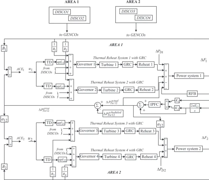
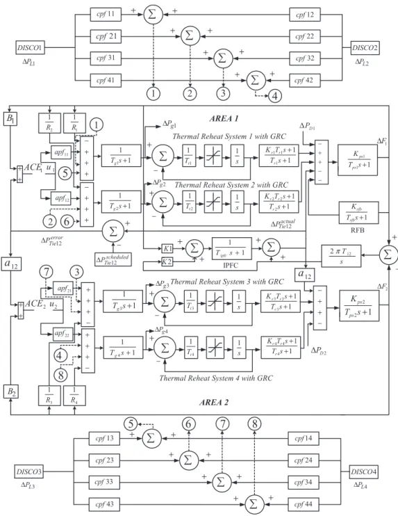
A two area multi unit interconnected power system has been proposed for AGC in deregulated environment. The system is widely used in literature for the design and analysis of AGC under deregulated scenario[6]. The block diagram representation of two area power system with IPFC and RFB in presence of GRC and TD under deregulated environment is shown inFig. 1. Area 1 comprises of two GENCOs with thermal power system of reheat turbine and GRC combinations and two DISCOs, Area 2 comprises of two GENCOs with thermal power system of reheat turbine and GRC combinations and two DISCOs as shown inFig. 1. A PIDF controller is considered for each area. The transfer function model of the above system is shown inFig. 2. InFig. 2,R1,R2andR3,R4are the
regulation parameters of thermal units for area 1 and area 2 respectively in p.u. Hz.B1andB2represent the frequency bias pa-rameters in p.u. MW/Hz.Tg1andTg2are the speed governor time
constants in sec for area 1;Tg3andTg4are the speed governor time
constants in sec for area 2;Tt1andTt2are the turbine time constant
in sec for area 1;Tt3andTt4are the turbine time constant in sec for
area 2;
D
PD1andD
PD2are the load demand changes in p.u.;D
PTieisthe incremental change in tie-line power (p.u.);KPs1andKPs2stands
for the power system gains; TPs1 and TPs2 represent the power
system time constant in sec;T12is the synchronizing coefficient in p.u. and
D
F1andD
F2are the system frequency deviations in Hz,. Forthermal plant a GRC of 3%/min[24]and a time delay of 50 ms[25]
are considered in the present work. The relevant parameters are given inappendix A.
As there are several GENCOs and DISCOs in the deregulated environment, there can be various contracts between GENCOs and DISCOs. If DISCOs having contract with GENCOs of the same control area then it is known as “poolco based transaction”. If DISCOs having contract with GENCOs of another area then it is known as
“bilateral based transaction”. If DISCOs violate the contract by demanding more than specified in the contract then it is known as
“contract violation based transaction”. To know the contracts be-tween GENCOs and DISCOs the concept of DISCO Participation Matrix (DPM) is introduced[5].
DPM is a matrix in which the number of rows is equal to the number of GENCOs and the number of columns is equal to the number of DISCOs in the system. The elements of DPM are indi-cated withcpfij which corresponds to fraction of total load
con-tracted by a DISCO towards a GENCO. The sum of all the entries in a
column in DPM is unity i.e.Pnicpfij¼1. InFig. 1GENCO1, GENCO2,
DISCO1 and DISCO2 are in area 1. GENCO3, GENCO4, DISCO3 and DISCO4 are in area 2. Then the corresponding DPM is written as[5]
DPM¼ 2 6 6 4 cpf11 cpf12 cpf13 cpf14 cpf21 cpf22 cpf23 cpf24 cpf31 cpf32 cpf33 cpf34 cpf41 cpf42 cpf43 cpf44 3 7 7 5 (1)
wherecpfrepresents“contract participation factor”i.e. p.u. MW load of a corresponding DISCO.
The scheduled steady state powerflow on the tie-line is given as[5].
DPscheduled
Tie12 ¼ ðDemand of DISCOs in area 1 to GENCOs in area 2Þ
ðDemand of DISCOs in area 2 to GENCOs in area 1Þ
(2) The actual tie-line power is given as
DPactualTie12 ¼2pT12
s ðDF1DF2Þ (3)
At any time, the tie-line power error is given by[5].
DPerrorTie12¼DPTieactual12 DPscheduledTie12 (4)
DPerror
Tie12 vanishes in the steady as the actual tie-line power flow
reaches the scheduled power flow. This error signal is used to
generate the respective Area Control Error (ACE) signals as in the traditional scenario[5].
ACE1¼B1DF1þDPerrorTie12 (5)
ACE2¼B2DF2þa12DPerrorTie12 (6) Fig. 3.Structure of PID controller with derivativefilter.
As there are two GENCOs in each area, ACEsignal has to be distributed among them in proportion to their participation in the AGC. Coefficients that distributeACEto GENCOs are termed as“ACE
Participation Factors (apfs)”. In a given control area, the sum of
participation factors is equal to 1. Hence,apf11,apf12are considered
asACEparticipation factor in area 1 andapf21,apf22are in area 2.
2.2. Controller structure and objective function
In the present paper, two dissimilar PIDF controllers have been
considered for the two area system [21]. The structure of PID
controller with derivativefilter is shown inFig. 3whereKP,KIandKD
are the proportional, integral and derivative gains respectively and
N is the derivative filter coefficient. The control inputs of PIDF controller are the respective ACEs and the output of PIDF control-lers are the input of power systemu1andu2shown inFig. 3. Fig. 5.General block diagram of redoxflow batteries in AGC.
The transfer function of the controller is given by: TFPID¼ KPþKI 1 s þKD Ns sþN (7) In the design of a modern heuristic optimization technique based controller, the objective function isfirst defined based on the desired specifications and constraints. Performance criteria usually considered in the control design are the Integral of Time multiplied Absolute Error (ITAE), Integral of Squared Error (ISE), Integral of
Time multiplied Squared Error (ITSE) and Integral of Absolute Error (IAE). ITAE criterion reduces the settling time which cannot be achieved with IAE or ISE based tuning. ITAE criterion also reduces the peak overshoot. ITSE based controller provides large controller output for a sudden change in set point which is not advantageous from controller design point of view. It has been reported that ITAE is a better objective function in LFC studies[21,26]. Therefore in this paper ITAE is used as objective function to optimize controller parameters of PIDF controller. Expression for the ITAE objective function is depicted in Eq.(8).
Table 1
Tuned controller parameters for Poolco based transaction without GRC, TD, IPFC and RFB.
Parameters and performance index Fuzzy PIDF
Controller parameters K1¼0.1253 K2¼0.1302 K3¼0.0924 K4¼0.0078 KP1¼ 0.8983 KI1¼ 0.971 KD1¼ 1.504 N1¼58.8709 KP2¼1.5299 KI2¼ 0.6979 KD2¼ 1.9265 N2¼70.8096 ITAE 11.7186 7.8174
Settling time TS(sec) DF1 15.42 20.05
DF2 17.88 19.60
DPTie 27.31 13.91
Peak over shoot DF1 0.0324 0.0212
DF2 0.0299 0.0169
DPTie 0 0.0089
Table 2
Tuned controller parameters for Poolco based transaction without GRC, TD (with IPFC and RFB).
Parameters and performance index With IPFC Only With IPFC and RFB
Controller parameters KP1 1.7134 % Improvement 1.7036 % Improvement
KI1 1.5927 1.9864 KD1 0.1827 1.9948 N1 57.0781 51.3204 KP2 0.8433 0.4245 KI2 0.6979 1.1173 KD2 1.0405 1.2433 N2 162.3066 87.742 ITAE 2.1414 72.6 1.8858 75.87
Settling time TS(sec) DF1 12.59 37.21 11.05 44.88
DF2 12.93 34.03 11.94 39.08
DPTie 9.09 34.65 7.83 43.71
Peak over shoot DF1 0.0115 45.75 0.01 52.83
DF2 0.0089 47.33 0.0077 54.43
DPTie 0.0052 41.57 0.004 55.05
Table 3
Re-tuned controller parameters for Poolco based transaction in presence of GRC and TD.
Parameters and performance index Without IPFC and RFB With IPFC only With both IPFC and RFB
Controller parameters KP1 1.2385 0.9201 1.5235 KI1 0.0424 0.2082 1.4186 KD1 0.4606 1.6679 0.0547 N1 246.9947 72.3479 220.3304 KP2 0.6672 0.5333 0.276 KI2 0.1205 0.0748 1.602 KD2 1.4102 0.0109 1.2598 N2 41.9896 172.8689 21.1966
ITAE 433.19 177.99 17.63 Without re-tuning
39.2789
Settling time TS(sec) DF1 unstable 54.86 15.52 20.90
DF2 unstable 44.60 18.05 21.44
DPTie unstable 48.13 15.07 21.41
Peak over shoot DF1 1.0468 0.6920 0.0855 0.1058
DF2 1.088 0.7047 0.1622 0.118
J¼ITAE¼
Ztsim 0
ðjDF1j þ jDF2j þ jDPTiejÞ,t,dt (8)
In the above equations,
D
F1andD
F2are the system frequency deviations;D
PTieis the incremental change in tie-line power;tsimisthe time range of simulation.
The problem constraints are the PIDF controller parameter bounds. Therefore, the design problem can be formulated as the following optimization problem.
Minimize J (9)
Subject to
KPminKPKPmax; KIminKIKImax; KDmin KD
KDmax; NminNNmax (10)
WhereJis the objective function andKPIDFminandKPIDFmax, are
the minimum and maximum value of the PIDF control parameters. The minimum and maximum values of PID controller parameters
Fig. 7.Dynamic responses of the system for poolco based transaction without TD&GRC (a) Frequency deviation of area 1 (b) Frequency deviation of area 2 (c) Tie-line power deviation.
are chosen as2.0 and 2.0 respectively. The range forfilter coef-ficient N is selected as 1 and 300.
2.3. Modelling of IPFC in AGC
The modelling of IPFC and RFB has been done in the same way as given in ref.[6]. However, in ref.[6]only an integral controller was used whose gain consists of products of a conventional control gain and fuzzy gain whereas in the present study a PIDF controller is proposed which increases the capabilities of IPFC and RFB in automatic generation control. Also, in the present manuscript the capabilities of IPFC and RFB are evacuated in the presence of
physical constraints such as Time Delay (TD) and Generation Rate Constraint (GRC).
The equivalent power injection model of IPFC is shown inFig. 4 [6]. IPFC is a combination of two or more SSSCs which are coupled via a common DC link. With this scheme, IPFC has the capability to provide an independently controllable reactive series compensa-tion for each individual line and also to transfer real power between the compensated lines. There has been growing interest recently in studying the IPFC modelling, its basic function to control power
flow among transmission lines and oscillation damping. The IPFC
installed in series with a tie-line and provides damping of oscilla-tions the tie-line power. InFig. 4,Vseis the series voltage magnitude
and4se is the phase angle of series voltage. The shunt converter
Fig. 9.Dynamic responses of the system for poolco based transaction with both IPFC&RFB (a) Frequency deviation of area 1 (b) Frequency deviation of area 2 (c) Tie-line power deviation (d) Change in generated powers of different GENCOs.
injects controllable shunt voltage such that the real component of the current in the shunt branch balance the real power demanded by the series converter. It is clear fromFig. 4that, the active and reactive power injections at the buses can be written as
Pinj;p¼ X n¼q;r VpVse;pnbpnsin qpqse;pn (11) Qinj;p¼ X n¼q;r
VpVse;pnbpncosqpqse;pn
(12)
Pinj;n¼ X n¼q;r
VnVse;pnbpnsinqnqse;pn
(13)
Qinj;n¼ X n¼q;r
VnVse;pnbpncosqnqse;pn
(14) where,Vse;pn¼Vse;in:qse;in and n¼q;r
2.4. Modelling of RFB in AGC
In an interconnected power system during the presence of small load perturbations and with optimized controller gains, the fre-quency deviations and tie-line power changes exist for long time durations. During such conditions the governor may not able to absorb the frequency deviations due to slow response and non-linearities present in the system. So, in order to reduce the fre-quency deviations and change in tie-line power, an active power source with quick response such as RFB can be expected to the most effective one[6,27]. The RFB are found to be superior over the other energy storage devices like superconducting magnetic energy storage (SMES) because of its easy operating at normal tempera-ture, very small losses during operating conditions and have long service life [20]. As RFB are capable of ensuring a very quick
response [6],
D
F1 is being used directly as the input commandsignal for RFB to control frequency. A general block diagram of the RFB used for AGC in the interconnected power system is shown in theFig. 5 [27]. During very low load duration battery charges and delivers the energy to the system during sudden load changes. The
dual converter performs both rectifier and inverter action. For
sudden step load perturbation the change of output of a RFB is given as[6].
DPrfb¼ Krfb
1þsTrfbD
F1 (15)
whereKrfbis gain of a RFB andTrfbis time constant of RFB in Sec.
3. Overview of differential evolution algorithm
Differential Evolution (DE) algorithm is a population-based
stochastic optimization algorithm recently introduced [22].
Ad-vantages of DE are: simplicity, efficiency&real coding, easy use and speediness. DE works with two populations; old generation and new generation of the same population. The size of the population is adjusted by the parameterNP. The population
con-sists of real valued vectors with dimension D that equals the
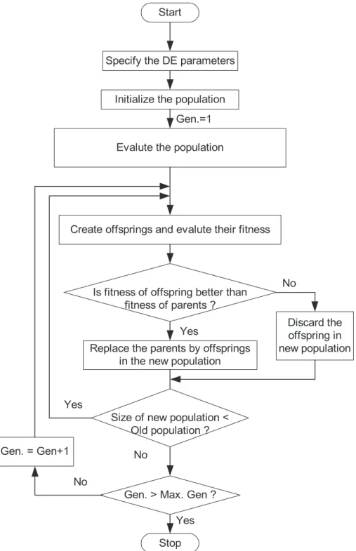
number of design parameters/control variables. The population is randomly initialized within the initial parameter bounds. The optimization process is conducted by means of three main oper-ations: mutation, crossover and selection. In each generation, in-dividuals of the current population become target vectors. For each target vector, the mutation operation produces a mutant vector, by adding the weighted difference between two randomly chosen vectors to a third vector. The crossover operation generates a new vector, called trial vector, by mixing the parameters of the mutant vector with those of the target vector. If the trial vector obtains a betterfitness value than the target vector, then the trial vector replaces the target vector in the next generation. Theflow
chart of DE approach is shown in Fig. 6. The DE algorithm is
explained in more detail in[24].
4. Simulation results and discussion 4.1. Implementation of DE
The simulations are carried out on an Intel, Core i-5 CPU of 2.5 GHz, 8 GB, 64-bit processor computer in the the MATLAB 7.10.0.499 (R2010a) environment. The model of the system under
study shown in Fig. 2 is developed in MATLAB/SIMULINK
envi-ronment and DE program is written (in.mfile). Initially, dissimilar PIDF controllers are considered for each area without considering the physical constraints (time delay, generation rate constraints), IPFC and RFB under poolco based transaction. The developed model is simulated in a separate program (by.mfile using initial popula-tion/controller parameters) considering a 20% step load increase in area 1. The objective function is calculated in the.mfile and used in the optimization algorithm. In the present study, a population size
ofNP ¼100, generation numberG ¼100, step size F¼0.8 and
crossover probability of CR ¼ 0.8 have been used. The strategy
employed is: DE/best/1/exp. Optimization is terminated by the pre specified number of generations for DE. One more important factor that affects the optimal solution more or less is the range for
un-knowns. For the very first execution of the program, a wider
Table 4
Tuned PIDF controller parameters for Bilateral based transaction with TD&GRC.
Cases/Parameters KP1 KP2 KI1 KI2 KD1 KD2 N1 N2
Without IPFC&RFB 0.3619 1.6064 0.0620 0.1213 1.3287 1.6686 193.6168 100.8839 With IPFC only 0.3619 1.6064 0.0620 0.1213 1.3287 1.6686 193.6168 100.8839 Both IPFC&RFB 1.9760 1.6497 1.0010 0.9535 1.5502 0.0209 146.4745 165.4745
Table 5
Performance index values under Bilateral based transaction.
Parameters Without IPFC&RFB With IPFC only Both IPFC&RFB
ITAE 3028.6 2930.5 64.2
TS(sec) DF1 unstable unstable 25.34
DF2 unstable unstable 27.23
DPTie unstable unstable 25.37
Peak over shoot DF1 3.0347 2.8912 0.2314
DF2 3.0427 2.9121 0.4542
Fig. 10.Dynamic responses of the system for bilateral based transaction (a) Frequency deviation of area 1 (b) Frequency deviation of area 2 (c) Tie-line power deviation (d) Change in generated powers of different GENCOs.
solution space can be given and after getting the solution one can shorten the solution space nearer to the values obtained in the previous iteration. The optimization was repeated 50 times and the
best final solution among the 50 runs is chosen as controller
parameters.
In the present study, the controller parameters are tuned at three transactions that take place in a deregulated environment i. e. Poolco, Bilateral and Contract violation based transactions. Under each transaction scenario, three cases are considered i.e. without IPFC&RFB, with IPFC only and with both IPFC &RFB. Initially, a two area power system without any physical con-straints is considered and the PIDF controller parameters are optimized under Poolco based transition. The superiority of PIDF over fuzzy controller is demonstrated in this case. Then physical constraints such as GRC and time delay are included in the sys-tem model and the PIDF controller parameters are retuned for different cases. To show the robustness of proposed approach, sensitivity analysis is performed under varied loading and system parameter conditions. The process is repeated i.e. the PIDF controller parameters are tuned under Bilateral and Contract violation based transactions in presence of physical constraints. Finally, the proposed approach is extended to a two area six unit hydro thermal power system with IPFC and RFB considering the physical constraints.
4.2. Case I: Poolco based transaction
In this scenario DISCOs have contract with GENCOs of the same area. It is assumed that the load disturbance occurs only in area 1. There is 0.1 (p.u. MW) load disturbance in DISCO1 and DISCO2, i.e.
D
PL1¼0.1 (p.u. MW),D
PL2¼0.1 (p.u. MW),D
PL3¼D
PL4¼0 (p.u.MW) as a result of the total load disturbance in area 1 i.e.
D
PD1¼0.2(p.u. MW). Considering that there is an equal participation of GENCOs. ∴DPM¼ 2 6 6 4 0:5 0:5 0 0 0:5 0:5 0 0 0 0 0 0 0 0 0 0 3 7 7 5
GENCO participates in load frequency control as defined as
following area participation factors i.e.apf11¼0.75;apf12¼0.25;
apf21¼0.5;apf22¼0.5. The scheduled tie-line power in this case is
zero. In steady sate, generation of GENCOs must match the demand of the DISCOs in contract with it. The generated power or con-tracted power supplied by the GENCOs is given as
DPgi¼
X4
j¼1
cpfij PLj (16)
By using Eq.(16)the values for
D
Pg1can be calculated asDPg1¼cpf11PL1þcpf12PL2þcpf13PL3þcpf14PL4 ¼ ð0:5Þ*ð0:1Þ þ ð0:5Þ*ð0:1Þ þ ð0Þ*ð0Þ þ ð0Þ*ð0Þ ¼0:1ðp:u:MWÞ:
Similarly, the values of
D
Pg2,D
Pg3andD
Pg4are obtained as 0.1(p.u. MW), 0 (p.u. MW) and 0 (p.u. MW) respectively.
In order to investigate the significance of considering the
physical constraints, two cases (Case A and Case B) are considered. In Case A, Time delay and Generation Rate Constraints are neglected. In Case B, Time delay and Generation Rate Constraints are considered. Initially, the physical constraints and IPFC&RFB are not considered in the system model. Thefinal PIDF controller parameters for the above case are obtained as explained in Section
4.1and given inTable 1. For comparison the results are compared with fuzzy logic controller (FLC). In case of FLC, ACE and its de-rivative are taken as input to the fuzzy logic controller and
triangular membership functions are used[28]. The membership
functions are used withfive fuzzy linguistic variables such as NB (negative big), NS (negative small), Z (zero), PS (positive small) and PB (positive big) for both the inputs and the output. The input scaling factors (K1, K2, K3andK4) of FLC are optimized using DE
optimization technique employing the same ITAE objective func-tion. The optimized parameters are given inTable 1. The perfor-mance index in terms of ITAE value, and settling times (2% band) in frequency and tie line power deviations are also shown in
Table 1. It is clear from Table 1 that, with the same system (without GRC, TD, IPFC and RFB) a less ITAE value is obtained with
PIDF controller (ITAE ¼ 7.817) compared to fuzzy controller
(ITAE ¼ 11.7186). The overall system performance in terms of
settling times and peak over shoots are also greatly improved with proposed DE optimized PIDF controller compared to fuzzy controller. Hence it can be conclude that PIDF controller outper-form fuzzy controller.
Then an IPFC is incorporated in the tie-line to analyze its effect on the power system performance. Finally, Redox Flow Batteries (RFB) is installed in the area 1 and coordinated with IPFC to study their effect on system performance. The optimized controller pa-rameters and the corresponding performance index are provided in
Table 2. It is clear fromTables 1 and 2that, ITAE value is further reduced to 2.1414 with only IPFC controller and smallest ITAE value (ITAE¼1.8858) is obtained with the coordinated application of IPFC and RFB. The corresponding performance indexes in terms of
Table 6
Tuned PIDF controller parameters for Contract violation based transaction with TD&GRC.
Cases/Parameters KP1 KP2 KI1 KI2 KD1 KD2 N1 N2
Without IPFC&RFB 0.2122 1.8576 0.1506 0.0160 1.9138 1.2309 270.4589 122.8947 With IPFC only 0.0498 1.6603 0.0407 0.0628 0.9035 1.6356 203.1226 46.4113 Both IPFC&RFB 1.6370 0.1720 0.8080 0.4726 0.1355 0.2939 77.2905 18.2415
Table 7
Performance index values under Contract violation based transaction.
Parameters Without IPFC&RFB With IPFC only Both IPFC&RFB
ITAE 30043.0 7803.4 109.4
TS(sec) DF1 unstable unstable 32.59
DF2 unstable unstable 34.16
DPTie unstable unstable 28.80
Peak over shoot DF1 3.5134 3.4846 0.2480
DF2 3.5142 3.5134 0.3874
settling time and peak overshoots are accordingly reduced. The percentage improvements with IPFC only and with coordinated application of IPFC and RFB compared the system without IPFC and RFB are also provided inTable 2. It can be seen fromTable 2that
system performance improves IPFC only and significant
improve-ments are achieved with coordinated application of IPFC and RFB. In the next step, physical constraints GRC and TD are included in
the system model and the results are shown inTable 3. For
com-parison, the performance indexes without re-tuning the controller parameters are also provided inTable 3. It can be observed from
Tables 1e3that the system performance degrades when GRC and TD are included in the system model. This is due to the reason that, when GRCs are considered, the generation can only be changed at a certain rate. Similarly, due to the presence of TD, the controller action is delayed and hence the system performance deteriorates.
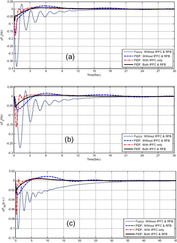
The dynamic performance of the system without GRC and TD for 20% step increase in load in area 1 is shown inFig. 7(aec). It can be seen from Fig. 7(aec) that the system is oscillatory with fuzzy controller. It is also evident fromFig. 7(aec) that oscillations are quickly suppressed with proposed DE optimized PIDF controllers. The system performance further improves with IPFC and the best dynamic performance is obtained with coordinated application of IPFC and RFB.
Fig. 8(aec) show the dynamic performance of the system with GRC and TD with/without IPFC and RFB for the above disturbance. It can be seen fromFig. 8(aec) that the system is highly oscillatory without IPFC and RFB in presence of GRC and TD. The dynamic performance is improved with IPFC and significant improvement in system performance is obtained with coordinated application of IPFC and RFB.
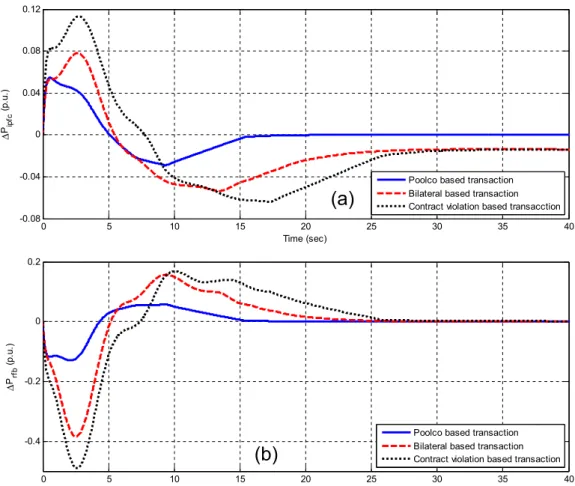
Fig. 12.Dynamic performances of system with both IPFC and RFB (a) Power deviation of IPFC under different transactions (b) Power deviation of RFB under different transactions.
Table 8
Sensitivity analysis under poolco based transaction.
Parameter variation % Change Settling time in (Sec) Peak over shoot ITAE
DF1 DF2 DPTie DF1 DF2 DPTie Nominal 0 15.52 18.05 15.07 0.0855 0.1622 0.0416 17.63 Loading condition þ25 15.55 18.06 15.70 0.0850 0.1377 0.0407 17.35 25 15.51 18.04 15.70 0.0851 0.1468 0.0410 17.48 Tg þ25 15.47 17.94 15.62 0.0854 0.1702 0.0419 17.89 25 16.12 18.16 15.82 0.0855 0.1532 0.0412 17.61 Tt þ25 15.48 18.01 15.63 0.0862 0.1620 0.0420 17.66 25 15.58 18.09 15.80 0.0849 0.1623 0.0412 17.75 T12 þ25 16.37 17.89 15.52 0.0844 0.1154 0.0424 17.32 25 15.39 18.33 16.00 0.0846 0.2245 0.0424 18.95
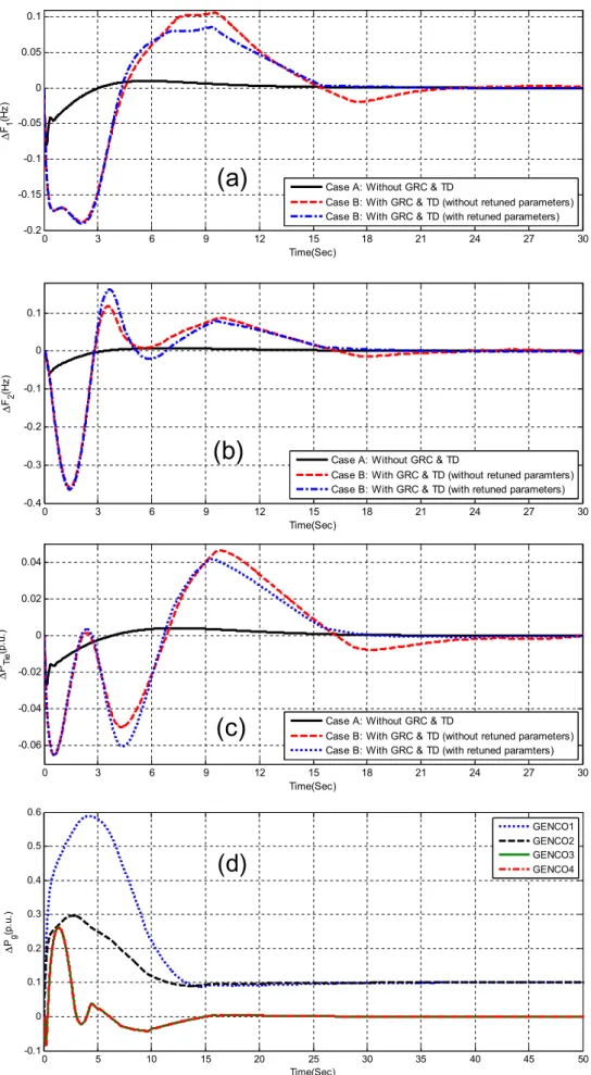
To evaluate the effect of GRC and TD and to show the need for retuning the controller parameters in presence of physical con-straints, the system dynamic responses with IPFC and RFB for both the cases (without GRC and TD: Case A and with GRC and TD: Case B) without/with retuned controller parameters are shown in
Fig. 9(aec). It can be seen fromFig. 9(aec) andTable 3that better dynamic responses in terms of peak over shoots and settling times are obtained when the controller parameter are retuned in pres-ence of physical constraints. For this case, the improvements in ITAE value are 58.92% with IPFC only and 95.93% with coordinated application of IPFC and RFB. The change in actual generated powers of various GENCOs in response to contract with DISCOs is shown in
Fig. 9(d). It is clear fromFig 9(d) that the GENCO1 and GENCO2 contribute 0.1 p.u. each and the sum of power generations of GENCOs in control area-1 matches with load demand of 0.2 pu MW.
4.3. Case II: bilateral based transaction
In this type of transactions, DISCOs have the freedom to contract with any of the GENCOs within own area or with another area. Now the DISCO participation matrix can be express as
DPM¼ 2 6 6 4 0:4 0:25 0:75 0:3 0:3 0:2 0 0:25 0:2 0:2 0:25 0:25 0:1 0:35 0 0:2 3 7 7 5
There is a load disturbance in DISCO1 is 0.15 (p.u. MW) and 0.05 (p.u. MW), 0.15 (p.u. MW), 0.05 (p.u. MW) in DISCO2, DISCO3, DISCO4 respectively. In this case, from Eq.(2)the scheduled tie-line power can be calculated as 0.0675 (p.u. MW).
Similarly from Eq.(16)the values of steady state power
gener-ated by the GENCOs are given as
D
Pg1 ¼ 0.2 (p.u. MW),D
Pg2¼0.0675 (p.u. MW),D
Pg3¼0.09 (p.u. MW),D
Pg4¼0.0425(p.u. MW).
The tuned PIDF controller parameters for Bilateral based
transaction with GRC and TD are given inTable 4. The various
performance indexes (ITAE, settling time and peak overshoot) under bilateral based transaction case are given inTable 5. It is
clear fromTable 5 that minimum ITAE value is obtained with
coordinated application of IPFC and RFB (ITAE¼64.2) compared
to only IPFC (ITAE ¼ 2930.5) and without IPFC and RFB
opti-mized PIDF controller (ITAE ¼ 3028.6). The improvements in
ITAE value for above case are 3.24% with IPFC only and 97.88% with coordinated application of IPFC and RFB. Consequently,
better system performance in terms minimum settling times in frequency and tie-line power deviations is achieved with pro-posed IPFC and RFB optimized PIDF controller compared to
others as shown inTable 5. Hence it can be concluded that in
this case also, the coordination of IPFC and RFB works satisfactorily.
It is worthwhile to mention that, in this example the values of GRC and TD as well as the magnitude of disturbance is so chosen that the system becomes unstable with IPFC for a better illustra-tion of coordinated applicaillustra-tion of IPFC and RFB. However, in the realistic system, IPFC may be enough to stabilize the system. The dynamic performance of the system for the above case is shown in
Fig. 10(aec). Critical analysis of the dynamic responses clearly reveals that coordinated application of IPFC and RFB significantly improves the dynamic performance of the system. Improved re-sults in settling times and peak overshoots of
D
F1,D
F2andD
PTieare obtained with proposed DE optimized PIDF controller with coordinated application of IPFC and RFB compared to others.
Fig. 10(d) shows the change in actual generated powers of various
GENCOs for the above case. It is clear from Fig 10(d) that the
steady state values of GENCOs are matching with the calculated values.
It is worthwhile to mention here that IPFC in general improves the AGC performance by controlling the tie-line powerflow. In case of Bilateral based transactions, the scheduled tie-line powerflow is 0.0675 (p.u. MW) as calculated according to the DPM matrix where as the load disturbance is 0.2 p.u. As the tie-line powerflow isfixed to its scheduled value, the role of IPFC which controls the tie-line powerflow is very limited for Bilateral based transactions. Due to the above reason a small improvement in ITAE value is obtained with IPFC only compared to the case when both IPFC and RFB are absent.
4.4. Case III: contract violation based transaction
In this case, there is a violation of contracts by demanding more power than that of specified in the contract. Considering Case II
again with a modification that 0.1 (p.u. MW) of excess power
demanded by DISCO1. Now
D
PD1 becomesDPD1¼DPL1þDPL2þDPuc1 ¼ 0.3 (p.u. MW) and
D
PD2 isun-changed. In this case, as contract violation done by DISCO1 the values of
D
Pg1andD
Pg2can be calculated as.DPg1;violation¼DPg1þapf11*DPuc1¼0:275 ðp:u:MWÞ
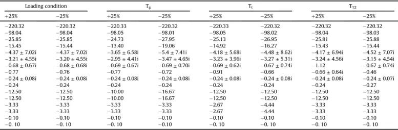
DPg2;violation¼DPg2þapf12*DPuc1¼ 0:0925 ðp:u MWÞ Table 9
System eigen values under parameter variation with poolco based transaction.
Loading condition Tg Tt T12 þ25% 25% þ25% 25% þ25% 25% þ25% 25% 220.32 220.32 220.33 220.32 220.33 220.32 220.32 220.32 98.04 98.04 98.05 98.01 98.05 98.02 98.04 98.03 25.85 25.85 24.73 27.95 25.13 26.95 25.81 25.88 15.45 15.44 13.40 19.06 14.92 16.27 15.43 15.44
4.37±7.02i 4.37±7.02i 3.65±6.58i 5.4±7.41i 4.18±5.68i 4.48±8.62i 4.17±6.94i 4.52±7.07i
3.21±4.55i 3.20±4.55i 2.95±4.41i 3.47±4.65i 3.23±3.96i 3.27±5.31i 3.24±4.56i 3.15±4.54i
0.68±0.67i 0.68±0.68i 0.69±0.67i 0.69±0.70i 0.69±0.62i 0.67±0.74i 1.12 0.67±0.74i
0.77 0.76 0.77 0.72 0.91 0.66 0.66±0.64i 0.46
0.24±0.08i 0.24±0.08i 0.24±0.08i 0.24±0.08i 0.24±0.08i 0.24±0.08i 0.24±0.08i 0.24±0.07i
0.24 0.24 0.24 0.24 0.24 0.24 0.24 0.27 12.50 12.50 10.00 16.67 12.50 12.50 12.50 12.50 12.50 12.50 10.00 16.67 12.50 12.50 12.50 12.50 3.33 3.33 3.33 3.33 2.67 4.44 3.33 3.33 3.33 3.33 3.33 3.33 2.67 4.44 3.33 3.33 0.10 0.10 0.10 0.10 0.10 0.10 0.10 0.10 0. 10 0. 10 0. 10 0.10 0. 10 0. 10 0. 10 0. 10
The values of
D
Pg3 andD
Pg4 are same as in Case II becausecontract violation is assumed in area 1.
Table 6gives the tuned PIDF controller parameters for con-tract violation based transaction with GRC and TD. The various performance indexes in terms of ITAE, settling time and peak overshoot for the above case are given inTable 7. It can be seen from Table 7 that improved results are obtained with coordi-nated application of IPFC and RFB compared to others. The
im-provements in ITAE value for contract violation based
transaction are 74.02% with IPFC only and 99.6% with coordi-nated application of IPFC and RFB. The frequency deviations and
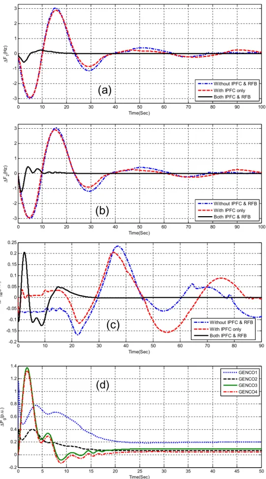
tie-line power are shown in Fig. 11(aec). It is evident from
Fig. 11(aec) that the system is unstable without IPFC and RFB as
well as with IPFC only. This due to the reason that the situation in Case II is further worsened by demanding excess power in area 1. It is also evident from Fig. 11(aec) that the system is stable with coordinated application of IPFC and RFB and the oscillations are quickly damped out. The change in actual generated powers of various GENCOs for contract violation
based transaction is shown in Fig. 11(d) from which it can be
seen that all the GENCOs contributes and their individual power generation matches with the calculated values. The output curves of IPFC and RFB for the above transactions are provided in Fig. 12(aeb). It is clear fromFig. 12(aeb) that both IPFC and RFB actively participate and contribute to the improvement of AGC.
4.5. Sensitivity analysis
Sensitivity analysis is done to study the robustness the system to changes in the operating conditions and system parameters
like speed governor time constant (Tg), Turbine time constant
(Tt), Synchronizing time constant (T12) in the range of þ25%
to25%. The performance index under normal and varied
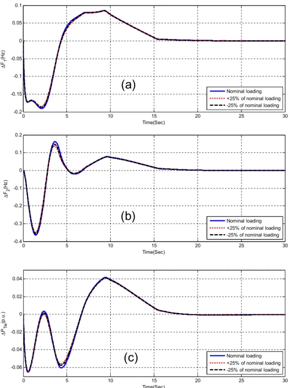
con-ditions is shown in Table 8. Table 9gives performance of the
system under varied operating load condition and system pa-rameters with proposed DE optimized PIDF controller employing both IPFC and RFB. Poolco based transaction with IPFC and RFB is considered for the sensitivity analyses as minimum ITAE value is obtained in that case compared to other cases. Critical
exami-nation ofTable 8clearly shows that the performance indexes are
more or less same and the effect of the variation in operating loading conditions and system time constants on the system performance is negligible. It is also evident fromTable 9that the eigen values lie in the left half of s-plane for all the cases thus maintain the stability. Hence it can be concluded that, the pro-posed control approach provides a robust and stable control satisfactorily. To complete the analysis, the dynamic perfor-mance of the system with the varied conditions of loading, Tg, Tt
and T12 are shown in Figs. 13e16. It can be observed from
Fig. 13(aec) that the effect of the variation of loading condition on the system performance is negligible. Also fromFigs. 14(aec),
15(aec) and16 (aec) clearly reveals that the effect of system
parameters (Tg,Tt and T12) on the system performance is
negligible.
4.6. Extension to two are six unit hydro thermal system
To demonstrate the ability of the proposed approach to cope with different sources of power generation, the study is further extended to a two area six unit hydro thermal power system with Generation Rate Constraint (GRC), time delay, IPFC and RFB as shown inFig. 17. For thermal units a generation rate constraints (GRC) of 3%/min is considered. For hydro unit, GRC's of 270%/min for raising generation and 360%/min for lowering generation are
considered[29]. Time delays can degrade a system's performance
and even cause system instability. In the present paper, a time delay of 50 ms is considered[25]. The relevant parameters are given in
Appendix B.
In this case only Poolco based transaction is considered. The area participation factors (apfs) of 0.4 for each thermal unit and 0.2 for hydro unit are assumed. A particular case of Poolco based trans-action is simulated based on the following DPM:
DPM¼ 2 6 6 6 6 6 6 4 0:35 0:35 0 0 0:35 0:35 0 0 0:30 0:30 0 0 0 0 0 0 0 0 0 0 0 0 0 0 3 7 7 7 7 7 7 5
By using Eq.(16), the changes in generated powers of different GENCOs are obtained as follows:
DPg1¼DPg2¼0:07 p:u: MW; DPg3¼0:06 p:u: MW; DPg4 ¼DPg5¼DPg6¼0 p:u: MW
Initially, the system without IPFC and RFB is considered and dissimilar PIDF controllers are chosen for each unit. A step load
disturbance of 20% is applied in area-1 and the final controller
parameters of PIDF controller for the Poolco based transaction are obtained as explained in Section 4.1. In the next step, an IPFC installed in the tie-line to analyze its effect on the power system performance. Finally, RFB is placed in area-1 and coordinated with
IPFC to study their effect on system performance. All the above conditions are tuned separately to obtainfinal controller
param-eters for PIDF controller and provided in Table 10. The
corre-sponding performance indexes are shown inTable 11. It can be
seen from Table 11that minimum ITAE value is obtained with
coordinated application of IPFC and RFB (ITAE ¼ 17.5927)
compared to the cases when only IPFC is present
(ITAE¼201.7875) and without IPFC and RFB (ITAE¼331.3957).
The improvements in ITAE value for above case are 39.11% with IPFC only and 94.69% with coordinated application of IPFC and RFB. Similar improvements are also observed in the settling times and peak overshoots.
The dynamic response of the system is shown inFig. 18(aec). It is clear fromFig. 18(aec) that in all the cases the system is stable as the magnitude of applied disturbance is small. However, responses are oscillatory without IPFC and RFB. The system performance
improves with the application of IPFC. Further, significant
im-provements in system performance are obtained with coordinated application of IPFC and RFB.Fig. 18(d) shows the change in actual generated powers of all the GENCOs for the above case from which it can be seen that the GENCO1, GENCO2 and GENCO3 of area 1 contribute 0.07, 0.07 and 0.06 p.u. MW respectively as calculated.
Finally sensitivity analysis for two area six unit hydro thermal system under poolco based transaction is performed as explained
before and the results are summarized in Table 12. It can be
observed fromTable 12that settling time, peak overshoots and ITAE values vary within acceptable ranges and are nearby equal to the respective values obtained with nominal system parameter. Hence, it can be concluded that the proposed controllers are robust and perform satisfactorily when system parameters changes in the range±25%.
The novel contributions of the present work are:
(i) PID controller with derivativefilter (PIDF) is proposed for AGC in a deregulated power environment. Afilter is used in derivative block to overcome the adverse affects of noise on PID controller.
(ii) Important physical constraints such as generation rate con-straints and time delay are included in the system model and PIDF controller parameters are optimized employing DE technique.
(iii) IPFC is then installed in the tie-line between the inter-connected areas for high speed control of tie-line power through the interconnections and to stabilize the area fre-quency oscillations quickly. The effect of presence of IPFC on the system performance is investigated.
(iv) In order to further improve the system performance, Redox Flow Batteries (RFB) which is an active power source with fast response characteristics is used. The impacts of IPFC
and RFB on the dynamic performance have been
investigated.
(v) Sensitivity analysis is performed by varying the operating load condition and system parameters in the range of±25% from their nominal values.
Table 11
Performance index values for two area six units system under Poolco based transaction.
Parameters Without IPFC&RFB With IPFC only Both IPFC&RFB
ITAE 331.3957 201.7875 17.5927
TS(sec) DF1 unstable 59.27 15.19
DF2 unstable 51.23 17.05
DPTie unstable 40.37 15.44
Peak over shoot DF1 1.0151 0.8122 0.1034
DF2 1.0609 0.8716 0.1628
DPTie 0 0.0763 0.0403
Table 10
Tuned PIDF controller parameters for two area six units system under Poolco based transaction.
Cases/Parameters Without IPFC&RFB With IPFC only Both IPFC&RFB
KP1 1.0714 1.1570 0.4925 KP2 0.6782 1.1109 0.3676 KP3 0.8396 1.0238 1.7358 KI1 0.2927 0.7070 1.8303 KI2 0.2313 0.1535 1.3551 KI3 0.2416 0.1499 1.3448 KD1 0.6553 0.0486 1.1918 KD2 1.8126 1.5941 0.9436 KD3 0.7453 0.8191 0.0594 N1 168.1922 53.5930 68.4587 N2 182.8122 157.4710 42.9118 N3 42.1501 187.6362 162.7192
5. Conclusions
In this paper, a Differential Evolution Algorithm (DE) optimized PID controller with derivativefilter (PIDF) has been proposed for Automatic Generation Control of multi area power system. Initially, a two area four unit thermal system is considered and the gains of PIDF controller parameters are optimized by employing DE tech-nique. It is observed that better dynamic performance are obtained with proposed DE optimized PIDF controller compared to a fuzzy logic controller. Time Delay (TD) and Generation Rate Constraints (GRC) have been considered to have a more realistic power system. To get better insight of AGC problem, inclusion of GRC and TD is important for the dynamic performance study of the system. The system has been investigated all possible of power transactions that
take place under deregulated environment. Interline powerflow
controller (IPFC) is then added in the tie-line for improving the
system performance. As the tie-line power flow is fixed to its
scheduled value, the role of IPFC which controls the tie-line power flow is very limited for bilateral based transactions. Due to the above reason a small improvement in ITAE value is obtained with IPFC only compared to the case when both IPFC and RFB are absent. Additionally, Redox Flow Batteries (RFB) is included in area 1 along with IPFC in order to improve the system performance. It is observed that in all the cases (poolco based, bilateral based and contract violation based) the deviation of frequency becomes zero in the steady state with coordinated application of IPFC and RFB which assures the AGC requirements. The proposed approach is also extended to a two-area six unit hydro thermal system. Sensi-tivity analysis is performed for both test systems under study by varying the system parameters and operating load conditions from their nominal values. From the simulation results it is observed that effect of system parameters and loading condition on the dynamic response of the power system is negligible.
Appendix
Nominal parameters of the system investigated are: A .Data for two area four unit thermal system[6].
Rated frequency¼60Hz,Rating of each area¼2000MW,Base power ¼ 2000 MVA, R1 ¼ R2 ¼ R3 ¼ R4 ¼ 2.4 Hz/p.u.MW,
B1 ¼ B2 ¼ 0.425 p.u.MW/Hz, Tg1 ¼ Tg2 ¼ Tg3 ¼ Tg4 ¼ 0.08s,
Tr1 ¼ Tr2 ¼ Tr3 ¼ Tr4 ¼10 s, Tt1 ¼ Tt2 ¼ Tt3 ¼ Tt4 ¼ 0.3 s,
Kp1 ¼ Kp2 ¼ 120 Hz/p.u. MW, Tp1 ¼ Tp2 ¼ 20s,
Kr1¼Kr2¼Kr3¼Kr4¼0.5;a12¼ 1, 2
p
T12¼0.545p.u.MW/Hz.B .Data for two area six unit hydro thermal system
B1¼B2¼0.425p.u. MW/Hz;KPS1¼KPS2¼120Hz/p.u. MW; TPS1¼TPS2¼20s;RTH1¼RTH2¼RTH3¼RTH4¼RHY1¼RHY2¼2.4Hz/ p.u.;TT1¼TT2¼TT3TT4¼0.3s;TSG1¼TSG2¼TSG3¼TSG4¼0.08s; KR1 ¼ KR2¼ KR3 ¼ KR4 ¼ 0.5; TR1 ¼ TR2 ¼ TR3 ¼ TR4 ¼10 s; T12 ¼ 0.0433; TGH1 ¼ TGH2 ¼ 48.7 s; TW1 ¼ TW2 ¼ 1 s; TRS1¼TRS2¼0.513;TRH1¼TRH2¼10;a12¼ 1.
C .Data for RFB and IPFC[6].
Krfb¼0.6787, Trfb¼0 s, Tipfc¼0.01 s, K1¼ 0.3, K2¼ 0.2622.
D .MATLAB Programme tofind system eigen values:
[A, B, C, D]¼linmod ('Model'); % Model is the SIMULINK model of system.
Eigen_Values¼eig(A); %Computes the system eigen values.
References
[1] O.I. Elgerd, Electric Energy Systems Theory: An Introduction, McGraw-Hill, New York, 1982.
[2] P. Kundur, Power System Stability and Control, McGraw-Hill, New York, 1994. [3] H. Bervani, T. Hiyama, Intelligent Automatic Generation Control, CRC Press,
2011.
[4] P. Bhatt, R. Roy, S.P. Ghoshal, Optimized multi-area AGC simulation in restructured power systems, Int. J. Electr. Power Energy Syst. 32 (1) (2010) 311e322.
[5] V. Donde, M.A. Pai, I.A. Hiskens, Simulation and optimization in an AGC system after deregulation, IEEE Tran. Power Syst. 16 (3) (2010) 311e322.
[6] I.A. Chidambaram, B. Paramasivam, Optimized load-frequency simulation in restructured power system with redoxflow batteries and interline power
flow controller, Int. J. Electr. Power Energy Syst. 50 (2013) 9e24.
[7] K.P.S. Parmar, S. Majhi, D.P. Kothari, LFC of an interconnected power system with multi-source power generation in deregulated power environment, Int. J. Electr. Power Energy Syst. 57 (2014) 277e286.
[8] N.G. Hingorani, L. Gyugyi, Understanding FACTS: Concepts and Technology of Flexible AC Transmission System, IEEE Press., 2000.
[9] A.V. Naresh Babu, S. Sivanagaraju, C.H. Padmanabharaju, T. Ramana, Power
flow analysis of a power system in presence of interline powerflow controller (IPFC), ARPN J. Eng. Appl. Sci. 5 (10) (2010) 1e4.
[10] L. Gyugyi, K.K. Sen, C.D. Schavder, The interline power flow controller concept: a new approach to powerflow management in transmission system, IEEE Trans. Power Deliv. 14 (3) (1989) 1115e1123.
[11] D. Kottick, M. Balu, D. Edelstein, Battery energy storage for frequency regu-lation in an island power system, IEEE Trans. Energy Convers. 8 (3) (1993) 455e459.
[12] H.J. Kunisch, K.G. Kramer, H. Dominik, Battery energy storage, another option for load frequency control and instantaneous reserve, IEEE Trans. Energy Conversions 1 (3) (1986) 41e46.
[13] Lu Chun-Feng, Liu Chun-Chang, Wu Chi-Jui, effect of battery energy storage system on load frequency control considering governor dead band and gen-eration rate constraint, IEEE Trrans. Energy Convers. 10 (3) (1995) 555e561. Table 12
Sensitivity analysis for two area six units system under poolco based transaction.
Parameter variation % Change Settling time in (Sec) Peak overshoot ITAE
DF1 DF2 DPTie DF1 DF2 DPTie Nominal 0 15.19 17.05 15.44 0.1034 0.1628 0.0403 17.5927 Loading condition þ25 15.24 17.08 15.45 0.1032 0.1567 0.0401 17.4978 25 15.12 17.02 15.44 0.1036 0.1690 0.0406 17.7026 TSG þ25 15.04 16.96 15.38 0.1036 0.1705 0.0408 17.6946 25 15.32 17.14 15.51 0.1031 0.1539 0.0399 17.4899 TT þ25 14.91 16.90 15.32 0.1044 0.1628 0.0405 17.5920 25 15.47 17.23 15.59 0.1023 0.1627 0.0401 17.6237 TRH þ25 15.26 17.11 15.45 0.1029 0.1619 0.0402 17.8214 25 15.04 16.94 15.41 0.1040 0.1641 0.0405 17.4003 TGH þ25 15.22 17.06 15.44 0.1028 0.1619 0.0401 17.8788 25 15.09 17.01 15.44 0.1043 0.1642 0.0406 17.0249 T12 þ25 15.47 16.90 15.32 0.1035 0.1185 0.0401 17.1093 25 14.57 17.22 15.57 0.1015 0.2214 0.0430 18.7608 R þ25 14.04 16.14 15.40 0.1089 0.1585 0.0395 17.7816 25 17.20 18.09 15.36 0.0978 0.1682 0.0418 17.8693
[14] L.H. Walker, 10 MW GTO converter for battery peaking service, IEEE Trans. Ind. Appl. 26 (1) (1990) 63e72.
[15] S.K. Aditya, D. Das, Battery energy storage for load frequency control of an interconnected power system, Electr. Power Syst. Res. 58 (3) (2001) 179e185.
[16] S.K. Aditya, D. Das, Application of battery energy storage system to load fre-quency control of an isolated power system, Int. J. Energy Res. 23 (3) (1999) 247e258.
[17] S.K. Aditya, D. Das, Load frequency control of an interconnected hydro-thermal power system with new area control error considering battery en-ergy storage facility, Int. J. Enen-ergy Res. 24 (6) (2000) 525e538.
[18] R.J. Abraham, D. Das, A. Patra, Load following in a bilateral market with local controllers, Int. J. Electr. Power Energy Syst. 33 (10) (2011) 1648e1657.
[19] S. Tetsuo, K. Toshihisa, E. Kazuhiro, Study on load frequency control using redox flow batteries, IEEE Trans. Power Syst. 19 (1) (2004) 660e667.
[20] K. Enomoto, T. Sasaki, T. Shigematsu, H. Deguchi, Evaluation study about redoxflow battery response and its modeling, IEEE J. Trans. Power Eng. 122 (4) (2002) 545e560.
[21] R.K. Sahu, S. Panda, S. Padhan, Optimal gravitational search algorithm for automatic generation control of interconnected power systems, Ain Shams Eng. J. 5 (3) (2014) 721e733.
[22] R. Stron, K. Price, Differential evolutionea simple and efficient adaptive scheme for global optimization over continuous spaces, J. Glob. Optim. 11 (4) (1995) 341e359.
[23] S. Das, P.N. Suganthan, Differential evolution: a survey of the state-of-the-art, IEEE Trans. Evol. Comput. 15 (1) (2011) 4e31.
[24] R.K. Sahu, S. Panda, U.K. Rout, DE optimized parallel 2-DOF PID controller for load frequency control of power system with governor dead-band nonline-arity, Int. J. Electr. Power Energy Syst. 49 (2013) 19e33.
[25] S. Panda, N.K. Yegireddy, S. Mahapatra, Hybrid BFOA-PSO approach for co-ordinated design of PSS and SSSC-based controller considering time delays, Int. J. Electr. Power Energy Syst. 49 (2013) 221e233.
[26] H. Shabani, B. Vahidi, M. Ebrahimpour, A robust PID controller based on imperialist competitive algorithm for load-frequency control of power sys-tems, ISA Trans. 52 (1) (2013) 88e95.
[27] K.P.S. Parmar, Load frequency control of multi-source power system with redoxflow batteries: an analysis, Int. J. Comput. Appl. 88 (8) (2014) 46e52. [28] R.K. Sahu, S. Panda, N.K. Yagireddy, A novel hybrid DEPS optimized fuzzy PI/
PID controller for load frequency control of multi-area interconnected power systems, J. Process Control 24 (01) (2014) 1596e1608.
[29] S.R. Khuntia, S. Panda, Simulation study for automatic generation control of a multi-area power system by ANFIS approach, Appl. Soft Compt. 12 (1) (2012) 333e341.