6349
Fuzzy Control Of A Mobile Robot In A Dynamic
Environment
Najmeh Asadi, Mazda Moatari, Padideh Rasouli, Elham Baneshi
Abstract: In this paper, a fuzzy control system is proposed to making intelligent the movement of a robot in a dynamic environment. We use a Kalman filter in order to determine the position of moving obstacle relative to the position of the robot at any moment. Our intelligent robot is able to change speed and direction of its movement at any moment, depending on the position of obstacle and the position of the target. Eventually, the simulation results confirm the system performance using MATLAB software.
Index Terms: Mobile Robot, Kalman Filter, Fuzzy Logic, Dynamic Environment
—————————— ◆ ——————————
1.
INTRODUCTION
The modern world that we are living in today, robots play a role more than attending imaginative stories or children's toys. We now see a widespread use of robots, and especially mobile robots, with a wide variety of applications in our environment. Types of intelligent robots come to help humans in difficult and dangerous environments such as space or at the bottom of the ocean. Also, the use of mobile robots is very common in order to serve humans with interesting and various applications and sometimes taking on very important and complex responsibilities such as disaster relief or help patients and people with disabilities or doctor's assistant in surgical operations. But the most basic issue with mobile robots is the performance of these robots in dynamic environments. The autonomous mobile robots must be planned in such a way that they can automatically find a path without collision with obstacles and reach the specified destination from a certain beginning point in order to properly carry out their duties. Therefore, an intelligent mobile robot should be programmed with knowledge and reasoning to have independent behavior. Our goal of this research is to making intelligent an autonomous mobile robot in a dynamic environment. The dynamic environment means an environment in which the obstacle position is changing at any moment. Using fuzzy logic is one of the methods to control the robot, in which lots of researches have been done so far. A robot arm system for rehabilitation is designed for patients with neurological and muscular disorders by force and position control using fuzzy logic [1]. Also, adaptive fuzzy controllers are designed for industrial applications [2]. In another research, a decentralized fuzzy controller for robot arms has been developed [3]. Also, a robust fuzzy controller is designed for robot arms [4]. Fuzzy logic in static environments is developed in [5] for mobile robot navigation. A sensor fusion technique is proposed to enhance the navigation rules using a modified fuzzy associative memory in [6].
And even a fuzzy-based approach to avoiding collision with obstacles for the human robot TWNHR-3 has been proposed in [7]. Another important subject that we are facing in this study is the issue of position estimation. With the introduction of Kalman filter in 1990, a great revolution in the problem of position estimation was created and many studies have been done in this regard. In the past, the extended Kalman filter and various types of it have been investigated for dealing with nonlinear estimation problem by replacing nonlinear equations with linear approximations [8]. Nam ∙ K ∙ H and his colleagues studied a second-order filter to access more accuracy [9]. Then an extended Kalman filter was designed to improve accuracy of approximation using the approximation of the measurement equations for the correction of last estimation instead of predicting the previous estimate [10]. Mira ∙ R ∙ K has checked an extended Kalman filter to transfer nonlinear equations of measurement to linear functions by selecting a suitable coordinate system [11]. It was also found in a study that a modified extended Kalman filter algorithm provides better performance rather than the estimated state vector from random equations by approximating nonlinear equations on the state vector which are calculated from algebraic equations [12]. In another study, the extended Kalman filter performance has been improved by changing the Taylor series approximation center [13]. Finally, Kalman filter has been used as a tool to estimate the obstacle position [14]. In the previous studies, the use of Kalman filter algorithm and fuzzy logic simultaneously, have not been tested. In this study by combining the powerful Kalman filter tool to estimate obstacle position and fuzzy logic to making intelligent the movement of autonomous mobile robot, an attempt has been made to design an intelligent control system and routing for an autonomous mobile robot in a dynamic environment. Also, by using input feedback linearization of the fuzzy system, we provide a new approach to control of mobile robots in dynamic environments. The proposed system is designed in such a way that our intelligent robot determines its own motion plan autonomously, by considering the position and the direction of moving obstacle, and also considering the position of target point. In this motion plan, by using fuzzy inference system and without human intervention, the robot starts to move from beginning point and estimates the position of obstacle sequentially by Kalman filter at any moment. with regard to direction of obstacle movement, the robot selects a direction to the target point in the way that it reaches target point without collision with moving obstacle. In this plan, the force applied to robot wheels is also determined according to the distance between robot and target by fuzzy inference system. So our
_______________________________
Authors affiliation:
Department of Electrical Engineering, Marvdash Branch, Islamic Azad University, Marvdasht, Iran
Email: [email protected]
Department of Electrical Engineering, Marvdash Branch, Islamic Azad University, Marvdasht, Iran
Email: [email protected]
Department of Electrical Engineering, Marvdash Branch, Islamic Azad University, Marvdasht, Iran
6350
autonomous mobile robot will be able to move from beginning point and travel along the path to target without colliding with moving obstacle and ultimately stop at the target point. Therefore, the innovation of this research is in the simultaneous use of Kalman filter and fuzzy logic to making intelligent a mobile robot, and also the input feedback linearization of the fuzzy system. It should be noted that the designed system, in the simplest way, offers very good performance. In section 2, the Extended Kalman Filter algorithm and its operation are expressed. In section 3, models of the moving obstacle and the mobile robot are described. Design of the intelligent control system is explained in section 4. Simulation results are presented in section 5. And finally, the conclusion is given in section 6.
2-EXTENDED
KALMAN
FILTER
This filter is actually a Kalman filter, which linearizes in the current average range. In this way, we can make estimates of the current calculation, using partial derivatives of process functions and measurements, even in the face of nonlinear relationships. Assuming that the process has a state vector in the form , it is expressed by the nonlinear randomized differential equation below :
(1)
And the measurement equation is as follows :
(2)
The random variables and respectively represent process noise and measurement noise. The nonlinear function connects the states in previous time step to the states in current time step and The non-linear function linkes the states to the measurement. The set of time update equations, and EKF filtering measurements, are as follows :
̂ ̅ ̂
(3)
̅ (4)
̅ ̅
(5)
̂ ̂ ̅ ̂ ̅ (6)
̅ (7)
In the time update equations, states and covariance are estimated from step to the current step. And in the updating equations of measurement, the estimated states and covariance are corrected. and are the Jacobins of measurement in step and is the noise covariance of measurement in step .
Table (1) shows an algorithm for estimating an obstacle position with a Kalman filter .
TABLE 1. ALGORITHM FOR ESTIMATING AN OBSTACLE POSITION WITH A KALMAN FILTER [15]
1-Estimate the initial target pose
2-Augment to state variable { ̇ } 3-Initialize
4- ( enabled) 5-{
6-Estimate next state variable and covariance matrix
7-Evaluate Jacobian of measurement model
│ 8-Calculate Kalman gain 9-Update state variable and covariance matrix
( ( ))
10-Output 11-}
3-MODELING
3-1 Model of the moving obstacle
Considering a moving arm as an obstacle, which moves in two-dimensions, the state vector of obstacle is defined as follows [15]:
{ ̇ ̇ } (8)
Where { } is coordinates of the fixed body of obstacle and { ̇ ̇ } represents derivation with respect to time. By assuming that the obstacle motion is uniform within a sample time interval and if is sufficiently small, then the higher order motion can be regarded as process noise in the form of
{ ̈ ̈ } . So the system model is defined as [15]:
(9)
Notes that the subscripts and indicate current and previous sampling time. The coefficient matrix of system model , and the coefficient matrix of process noise , are defined as follows [15]:
* + * +
* + [ ]
(10)
The measurement model from a pin-hole camera model, is expressed in the following vector equation [15]:
(11)
Where is the real measurement vector and is the estimated measurement vector based on the camera model and stands for the measurement noise of the camera, which may be caused by different natural conditions. This kind of noise can be considered as Gaussian noise and obeys the normal distribution [15].
3-2 Model of the mobile robot
6351
Fig 1. omnidirectional mobile robot model [16]
The applied force which determines the translational motion of the robot is given by the following equation [16]:
(12)
To convert the applied force F into the driving input torque to individual wheel, we need to define the dynamic model of the robot. The driving system for each assembly can be modeled by [16]:
̇ (13)
Where is the moment of inertia of the wheel around the driving shaft, is the rotational rate of the wheel, is the viscous friction factor for the wheel, is the radius of the wheel, is the driving gain factor and is the driving input torque. Define the state variable for the robot as ̇ ̇ ̇ and the manipulated variable as . Denote as the moment of inertia of the robot and as the distance between any assembly and the center of gravity of the robot, the dynamic model of the robot is as follows [16]:
̇ (14)
Where the matrixes A and B are equal to [16]:
[
̇
̇
]
[
√
√
√
√
]
(15) Apparently, the system is nonlinear and coupled. Nevertheless, using feedback lineization, we know that control
, can transform Equation (14) into the following form [16]:
̇ (16)
Where ̈ is the new control signal to be determined. is the desired acceleration of robot and is the desired orientation of the robot. For this holomonic omnidirectional robot, the orientation and the position can be controlled independently. In the following discussions, the orientation of the robot is assumed to be kept unchanged, i.e.,
̈ [16].
4-THE
INTELLIGENT
CONTROL
OF
ROBOT
In this research, intelligent control of robot in a dynamic environment means the choice of a path, which the robot chooses completely independently and without human intervention and this path can bring the robot to the target without collision with the obstacle. The proposed fuzzy control system, which is designed using Fuzzy Mamdani systems, consists of two separate Fuzzy control systems, including a Force Fuzzy Control System, and a Rotation Angle Fuzzy Control System. Force Control means that, by determining the distance between itself and the target, the robot determines its own motion force. So that, at long distances with more force and at near distances with less force, moves toward the target. until it finally stops at the target. Rotation Angle Control, allows the robot to instantly detect the position of obstacle and the position of target relative to its own location, and to change its direction, in order to avoid obstacle and approaching the target.
4-1 Design of the Force Fuzzy Control System
In order to control the applied force to robot wheels, a fuzzy system is designed with 1 input and 1 output, which at any moment determines amount of the applied force to robot wheels by considering the distance between robot and target. The input of this system; , is the distance between robot and target. for this variable 4 fuzzy sets are defined as " ", " ", " " and " ", which are briefly named as ,
, , and . The output of this system; , is the applied force to robot wheels. This variable also belongs to four fuzzy sets, which include " ", " ", " "and " ", and are named as , , , and respectively.
The task of this controller system, which is designed using Mamdani fuzzy model, is to determine the amount of output force and is completely dependent on the distance between robot and target. The scenario of this system is: the more the distance between robot and target is, the greater the force applied to robot, and as the distance decreases, the system output will also decreases. Table (2) is the rule base, which consists of 4 fuzzy rules in order to fulfill system's task.
TABLE 2.RULE BASE OF THE FORCE CONTROL SYSTEM
R2
Z VC C FA
Z VS
L S
L FS
6352
a poor performance of this system, the possibility of collision with obstacle is very probable in our dynamic environment. On the other hand, the system must also monitor the target, and adjust the robot's path so that robot eventually reaches target. This controller has 3 input variables called , and , which are respectively "The obstacle position relative to robot", "The target position relative to robot" and "The subtraction of the distance between robot and obstacle and the distance between robot and target". The variable α, which is "The rotation angle of robot", is defined as the single output of this system. Fuzzy sets of this variables are as follows:
The variable belongs to 4 fuzzy sets " ", " ", " " and " ", which are briefly called as , , and respectively. The variable belongs to 5 fuzzy sets called as , ,
, and , which are briefly called as , , , and . And the last input of this system; belongs to 2 fuzzy sets " " and "Far", called and respectively. α; The output of this system also belongs to 5 fuzzy sets called as " ", " ", " ", " " and " " Which are briefly named as , , , , and . In order to perform a desirable task, the rule base of this system consist of 40 fuzzy rules, which are shown in Table (3).
TABLE 3.RULE BASE OF THE ANGLE CONTROL SYSTEM Theta2 L LD L LU R RU R RD Z Z T L LD 2 2SL 1 1SL 1 1SR 1 2SR G GS N N R R12 L LU 2 2SL 1 1SL 1
1SR1 2SR G GS R RU 2 2SL 1 1SL 1
1SR1 2SR G GS R RD 2 2SL 1 1SL 1
1SR1 2SR G GS L LD G GS 1 1SL 1 1SR 1 2SR G GS D FA L LU 2 2SL G GS 1 1SR 1 2SR G GS R RU 2 2SL 1 1SL G GS 1 2SR G GS R RD 2 2SL 1 1SL 1 1SR G GS G GS Theta1
It is worth noting that the forces applied to the robot wheels (control forces) will ultimately be a combination of force and angle (the outputs of the fuzzy system), and .
(17)
5.
SIMULATION
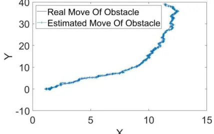
As we know, the robot's purpose in this system is to reach to the coordinates of the target point without collision with the moving obstacle. In order to achieve this goal, robot must decide at any moment that with how much force and at what angle to move. The obstacle position is estimated at any moment by Kalman filter. Then, our intelligent robot, considering the position of obstacle and target, measures the distances between itself and obstacle and target. Also, robot considering the Current and previous coordinates of obstacle, will be able to detect the direction of obstacle's motion. Therefore, robot, with the available information, assesses force and angle of its motion to reach to the target without collision with obstacle. After starting to move in a collision-free path to target, it stops at the target. In order to test the performance of proposed system, simulations are carried out in two steps. In the first step, the estimation of moving obstacle position and, in the second step, the results of proposed system's performance are displayed in different situations.
5-1 Step 1
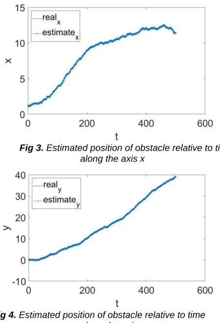
At this step, with the knowledge of the system model and the measurement model, the obstacle position is estimated at any given moment. Figures 2 to 4 represent results of this simulation.
6353
Fig 3. Estimated position of obstacle relative to time along the axis x
Fig 4. Estimated position of obstacle relative to time along the axis y
As it can be seen, the estimated values are very close to the real values.
5-2 Step 2
At this step, simulations in different scenarios are taken in terms of coordinates of the begining point of robot's motion and target point. The results of these simulations are shown below.
Case A:
The target’s coordinates: The robot's initial coordinates:
Fig 5. The path of robot, obstacle and target along axes x and y (Case A)
Fig 6. The path of robot, obstacle and target, relative to time along axis x (Case A)
Fig 7. The path of robot, obstacle and target, relative to time along axis y (Case A)
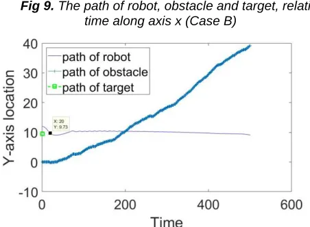
Case B:
The target’s coordinates: The robot's initial coordinates:
6354
Fig 9. The path of robot, obstacle and target, relative to time along axis x (Case B)
Fig 10. The path of robot, obstacle and target, relative to time along axis y (Case B)
Case C:
The target’s coordinates: The robot's initial coordinates:
Fig 11. The path of robot, obstacle and target along axes x and y (Case C)
Fig 12. The path of robot, obstacle and target, relative to time along axis x (Case C)
Fig 13. The path of robot, obstacle and target, relative to time along axis y (Case C)
As the images are illustrative, in all cases, robot has reached the goal without collision with the obstacle. For each case, three images are displayed. In all simulation results, the first image shows the path of robot, obstacle and the coordinates of target point along axes x and y , the second image shows the path of robot, obstacle and the coordinates of target point relative to time along x-axis and the third image shows the path of robot, obstacle and the coordinates of target point relative to time along y-axis. At some points in the images of axes x and y, it seems that robot has hit obstacle but by referring to these points in the images that are relative to time, it has been shown that at the given time there was no collision.
6-
CONCLUSION
In this research, we tried to use the Kalman filter algorithm and fuzzy logic simultaneously, and also the linearization of input feedback of the fuzzy system, to making intelligent and controlling mobile robots in dynamic environments. Using the Kalman filter to estimate the obstacle position, provides detailed information about the position of the moving obstacle, to the robot. Then, the fuzzy control system, consisting of force control and angle control, has succeeded in achieving the target in addition to a desirable performance in order to avoid the moving obstacle. Finally, it can be concluded that the application of the proposed methodology and design, despite the simplicity, has been successful.
REFRENCES
[1] Ming-Shaung Ju, Chou-Ching K. Lin, Dong-Huang Lin, Ing-Shiou Hwang, and Shu-Min Chen, A Rehabilitation Robot With Force-Position Hybrid Fuzzy Controller: Hybrid Fuzzy Control of Rehabilitation Robot, IEEE Transactions on neural systems and rehabilitation engineering, Vol. 13, No. 3, September 2005.
[2] Marius-Constantin Popescu, Ilie Borcosi, Onisifor Olaru, Luminita Popescu, Florin Grofu, The simulation hybrid fuzzy control of Scara robot, Wseas transactions on systems and control, 2008.
[3] Yaochu Jin, Decentralized Adaptive Fuzzy Control of Robot Manipulators, IEEE Transactions on systems, man , and cybernetics-Part B: cybernetics, Vol. 28, No. 1, February 1998.
[4] C Ham, Z Qu, R Johnson, Robust fuzzy control for robot manipulators, IEE Proceedings-Control Theory and Applications, 2000.
[5] Ngangbam Herojit Singh and Khelchandra Thongam, Mobile robot navigation using fuzzy logic in static environment, 6th International Conference on Smart Computing and Communications, ICSCC 2017, 7-8 December 2017, Kurukshetra, India.
[6] S.Parasuraman, sensor Fusion for Mobile Robot navigation: Fuzzy Associative memory, International Symposium on Robotics and Intelligent Sensors 2012 (IRIS 2012)
6355
[8] Kalman, R.E. and R.S. Bucy, New results in linear filtering and prediction theory. Journal of basic engineering, 1961. 83 :)3(p. 95-108.
[9] Nam, K. and M.-J. Tahik, A second-order stochastic filter involving coordinate transformation. IEEE transactions on automatic control, 1999. 44(3): p. 603-608.
[10] Bellaire, R.L., E.W. Kamen, and S.M. Zabin. New nonlinear iterated filter with applications to target tracking. in SPIE's 1995 International Symposium on Optical Science, Engineering, and Instrumentation. 1995. International Society for Optics and Photonics.
[11] Mehra, R., A comparison of several nonlinear filters for reentry vehicle tracking. IEEE Transactions on Automatic Control, 1971. 16(4): p. 307-319.
[12] Wall, D. and F. Gaston. Modified extended Kalman filtering. in Digital Signal Processing Proceedings, 1997. DSP 97., 1997 13th International Conference on. 1997. IEEE.
[13] Chui, C., G. Chen, and H. Chui, Modified extended Kalman filtering and a real-time parallel algorithm for system parameter identification. IEEE Transactions on Automatic Control, 1990. 35(1): p. 100-104.
[14] Zezhong, X., et al. Position estimation for a mobile robot with augmented system state. in Neural Networks and Brain, 2005. ICNN&B'05. International Conference on. 2005. IEEE.
[15] Dong, G. and Z.H. Zhu, Autonomous robotic capture of non-cooperative target by adaptive extended Kalman filter based visual servo. Acta Astronautica, 2016. 122: p. 209-218.
![Fig 1. omnidirectional mobile robot model [16]](https://thumb-us.123doks.com/thumbv2/123dok_us/8644077.1433785/3.612.59.247.63.244/fig-omnidirectional-mobile-robot-model.webp)