Logarithmic Edge Detection with Applications
Karen A. Panetta, Eric J. Wharton Tufts University, Medford, MA, United States Email: [email protected], [email protected]
Sos S. Agaian
The University of Texas at San Antonio, San Antonio, TX, United States Email: [email protected]
Abstract—In real world machine vision problems, numerous issues such as variable scene illumination make edge and object detection difficult. There exists no universal edge detection method which works well under all conditions. In this paper, we propose a logarithmic edge detection method based on Parameterized Logarithmic Image Processing (PLIP) and a four-directional Sobel method, achieving a higher level of independence from scene illumination. We present experimental results for this method, and compare results of the algorithms against several leading edge detection methods, such as Sobel and Canny. To compare results objectively, we use Pratt’s Figure of Merit. We demonstrate the application of the algorithm in conjunction with Edge Preserving Contrast Enhancement (EPCE), which is an image enhancement method dependent on the raw output of an edge detection kernel. This shows that the use of this edge detection algorithm results in better image enhancement, as quantified by the Logarithmic AME.
Index Terms—Parameterized Logarithmic Image Processing, Edge Detection, Image Enhancement, Measure of Enhancement
I. INTRODUCTION
Effective edge detection is an important step for many important areas, such as machine vision and automated interpretation systems, and is often used as the front-end processing stage for higher level object recognition and interpretation systems [1][2][3]. An edge detector is defined as a mathematical operator of small spatial extent that responds in some consistent manner to these discontinuities, usually classifying every image pixel as either constituting an edge or not [4]. Much research has been spent developing effective edge detection algorithms. These can generally be classified as gradient- based [5][6], template matching [7], or parametric models [8]. Despite this extensive research, the task of finding edges that correspond to the true physical boundaries remains a difficult problem [1].
In [9], edge detection methods based upon Logarithmic Image Processing (LIP) were first proposed. A contrast operator was introduced for edge detection with impressive results. It was proven that this method is not dependent on the intensity level of the illumination and
that it is robust in small scale changing illumination, specifically at the pixel-by-pixel scale.
Further, an LIP based Sobel operator has been proposed [10], which works in the same manner as the standard Sobel operator but using LIP arithmetic. In the same manner as the LIP contrast operator, this also has the same desirable properties; independence of overall illumination and pixel-by-pixel changes in illumination. These methods, however, can be improved upon.
In [11], a parameterization of the LIP model was proposed, called Parameterized LIP (PLIP). By parameterizing the model instead of simply using the same values as in linear image processing, better results were obtained. By parameterizing the LIP Sobel operator, we will show a similar improvement with more accurate edge detection results.
Further, the Sobel operator is only applied in the horizontal and vertical orientations. However, it is possible to combine the two classical LIP methods to improve results with diagonal edges. By including a diagonal PLIP Sobel filter, edges which are commonly missed by the horizontal and vertical Sobel filters are detected. These methods can also be extended to any edge detection methods for better results.
These new parameterized operators can then be used for image enhancement. An image enhancement method which is dependent on the raw output of an edge detection kernel, called Edge Preserving Contrast Enhancement (EPCE) has been introduced. It has been shown that the quality of the edge detection has a major effect on the enhancement using this algorithm, and better edge detection methods results in better image enhancement [13]. By using these proposed edge detection methods, we will show improved image enhancement, as quantified by the Logarithmic AME measure of image enhancement.
will show that, on the basis of these objective measures and visual inspection, the PLIP edge detection methods achieve better edge detection and image enhancement.
In this paper, we introduce a parameterized edge detection method. The proposed algorithm modifies well known edge detection methods for better results, with the goal of a simple and quick edge detection process. We further present the image enhancement application, demonstrating the use of the proposed edge detection methods for the EPCE algorithm.
The paper is organized as follows: Section 2 presents necessary background information including the Parameterized Logarithmic Image Processing (PLIP) model, Pratt’s Figure of Merit, and the Logarithmic AME measure of image enhancement. Section 3 presents the proposed algorithm. Section 4 presents the results of computer simulations and makes a comparison between the proposed algorithm and several leading edge detection algorithms. Section 5 presents the EPCE algorithm and presents results using the different edge detection algorithms, demonstrating the results of the proposed algorithm. Section 6 presents a discussion of results and concluding comments are made.
II. BACKGROUND
In this section, we present necessary background information. This includes the Parameterized Logarithmic Image Processing (PLIP) model, Pratt’s Figure of Merit, and the Logarithmic AME measure of enhancement.
A. Parameterized Logarithmic Image Processing Model The Parameterized Logarithmic Image Processing (PLIP) model was introduced by Panetta, Wharton, and Agaian to more accurately process images [11]. It gives a non-linear framework for image processing which is designed to both maintain the pixel values inside the allowable range as well as more accurately process images from a human visual system point of view. To accomplish this, the images are processed as gray tone functions. The gray tone function is arrived at as follows:
)
,
(
)
,
(
i
j
M
f
i
j
g
(1)Where f( i, j ) is the original image function, g( i, j ) is the output gray tone function, and M is the maximum value of the range. It can be seen that this gray tone function is much like a photo negative.
The PLIP model can be summarized as follows:
)
(
M
ab
b
a
b
a
J
(2)g
M
k
b
a
M
k
b
a
4
)
(
)
(
(3)(
)
(
)
1b
a
b
a
M
M
M
(4) ¸¸ ¹ · ¨¨ © § ) ( 1 ln ) ( ) ( M f M a O O M E (5) » » ¼ º « « ¬ ª ¸¸ ¹ · ¨¨ © § E O O M / 1 1 ) ( exp 1 ) ( ) ( M f M a (6)
where we use
as PLIP addition,4
as PLIP subtraction, andas PLIP multiplication. Also, a and b are any grey tone pixel values, cis a constant, M is the maximum value of the range, and ȕ is a constant. Ȗ(M), k(M), and Ȝ(M) are all arbitrary functions. In [11], it is found that the best value of these arbitrary functions is Ȗ(M),k(M), and Ȝ(M) = 1026.
B. Pratt’s Figure of Merit
Pratt’s Figure of Merit is used to compare the result of an edge detection algorithm to the known ground truth [12][6]. It returns a number between 0 and 1 based upon the quality of the edge detection, with 1 being the best. The measure is based upon three things, detection, localization, and spurious response. This means that the score is based upon all edges being found, all edges being placed in the correct location, and no false alarms. Pratt’s Figure of Merit is computed as follows:
¦
AN
k A
I
N
d
k
N
F
1 2)
(
1
1
}
,
max{
1
D
(7)where NI is the number of actual edges, NA is the number of detected edges, d(k) denotes the distance from the kth actual edge to the corresponding detected edge, and Į is a scaling constant set to 1/9 as in Pratt’s work.
C. Measure of Enhancement
In general, image enhancement performance and its automation are judged subjectively. For applications involving a measure of image enhancement, the optimal enhanced image is not known, and cannot be used for comparison purposes. There have been many differing definitions of an adequate measure of performance based on contrast [14][15][16][17].
Recently, Panetta, Wharton, and Agaian introduced the Logarithmic AME measure of image enhancement [13]. It was shown that this is an effective method for selection of parameters and as an objective means of quantifying enhancement performance. These measures are calculated as follows:
¦¦
¸¸ ¹ · ¨ ¨ © § 4 ) 1 2 2 11 1 max:, min:, , : min , : max 2 1 ln 20 1 1 ) ( log k i k j w l k w l k w l k w l k k k I I I I k k AME (8)
¦¦
4)
1 2
2 1
1 1 max:, min:, , : min , : max 2 1 1 ) ( log k i k
j w kl
w l k w l k w l k k k I I I I k k AMEE ¸ ¸ ¹ · ¨ ¨ © § 4 w l k w l k w l k w l k I I I I , : min , : max , : min , : max
These measures are calculated by dividing an image into k1 x k2 blocks, calculating the measure for each, and averaging the results across the entire image. For a more in depth analysis of these measures, refer to [13].
III. PROPOSED ALGORITHM
Due to the importance of accurate edge detection for a number of image processing applications, it is necessary to continue researching more accurate and effective edge detection methods. It is common for edge detection algorithms to make use of first or second order derivatives because an edge can be classified as a unit step. However, this is an ideal definition which is rarely seen in practice [1].
While such ideal edges are rarely seen in practice, most effective edge detectors see an edge as a region of high contrast. This is because the unit step can be effectively detected as a region of high contrast, even in the presence of noise. As such, the LIP contrast between two pixels f( x, y ) and f( x’, y’ ) has been defined in [9] to be:
)
'
,
'
(
)
,
(
) ' ,' ( ), ,
(
f
x
y
f
x
y
C
xy x y4
(10)
( , ), ( ', ')max f x y f x y C
( , ), ( ', ')min f x y f x y
4 (11)
This contrast estimator has many important properties. It is independent on the intensity level of the illumination and it is robust in small scale changing illuminations, specifically at the pixel-by-pixel scale. Manipulations of the light intensity formula used to derive the LIP model can be used to prove the former, and the latter can be shown by modeling an image as the LIP summation of
the objects plus the illumination [9].
To construct an edge detector using contrast operator, one first defines a neighborhood, A, around a given pixel f( x, y ). The contrast is then measured between the given pixel and every other pixel in the neighborhood using the contrast operator. Finally, the weighted sum of these contrast measurements is taken to determine the likelihood that the pixel is an edge. This is done according to the following formula:
¦
A y x y x
y x y x
C
A
count
y
x
E
) ' ,' ( ), , (
) ' ,' ( ), , (
)
(
1
)
,
(
(12)
Where count(A) is the number of pixels in A. Finally, the data is thresholded to produce the binary output.
This can be extended using any edge detection kernel of any size. For example, the simple 2 x 2 kernel:
1 1 1 -1 yields the following edge detection formula:
(
,
)
(
,
1
)
4
1
)
,
(
x
y
f
x
y
f
x
y
E
)
1
,
1
(
)
,
1
(
4
f
x
y
f
x
y
(13)
The LIP based Sobel algorithm has been introduced [10]. It functions in the same manner as the standard Sobel kernels, using the LIP arithmetic operations in place of classical linear arithmetic. The magnitude of horizontal and vertical Sobel operators is then taken as the likelihood that a given pixel is an edge. As will be seen in the results, however, this has a tendency to miss diagonal edges.
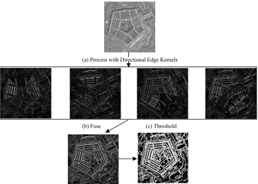
(a) Process with Directional Edge Kernels
(b) Fuse (c) Threshold
To address this problem, we make use of multi-directional Sobel kernels, which apply the same standard Sobel operator with diagonal orientation. The horizontal and vertical filters are as follows:
1 2 1 1 0 -1 0 0 0 2 0 -2 -1 -2 -1 1 0 -1
In order to construct the diagonal filter, it is necessary to use a 5x5 block instead of a 3x3 block. Therefore, the diagonal kernels are as follows:
1 -1
0 2 -2 0
-1 0 1 -1 0 1
-2 0 0 2
-1 1
Where all blank spaces are 0. It is important to note that, for both kernels, PLIP arithmetic is used. This information is collected for all four directions, and then must be combined in some manner.
It can be seen that these edge detectors work in the general format of the diagram shown in figure 1. An input image is processed with several edge detection
kernels, for example the directional Sobel kernels, and this information is somehow fused. Traditionally, this fusion took the form of a magnitude estimator which would fuse n edge detector results:
¦
2n
Fused
E
E
(14)As the output of PLIP operations is always an image, this type of fusion is unnecessary. We instead find that it is effective to add the images using PLIP addition:
¦
nFused
E
E
(15)where the summation uses PLIP addition, as shown in figure 1.
IV. COMPUTER SIMULATIONS: EDGE DETECTION
In this section, we show the results of computer simulations using the edge detection method alone. For synthetic images, we will use Pratt’s Figure of Merit (PFOM) to assess results. In order to quantify the performance of an edge detection algorithm using Pratt’s Figure of Merit, the results of an edge detection algorithm must be compared against the known edges of the image.
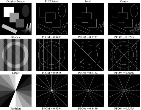
Original Image PLIP Sobel Sobel Canny
Shapes PFOM = 0.9439 PFOM = 0.7737 PFOM = 0.8795
Target PFOM = 0.9555 PFOM = 0.8182 PFOM = 0.8886
Partition PFOM = 0.9394 PFOM = 0.8439 PFOM = 0.9375
For this reason, we can use PFOM only for synthetic images. We will demonstrate the performance of the algorithm using natural images with visual assessment.
Figure 2 shows the results for several synthetic test images. The first column shows the original images. The second column shows the results of the images using the proposed algorithm, and the third and fourth columns show the results of Sobel and Canny, respectively.
It can be seen from the results in Figure 2 that the proposed algorithm outperforms the Sobel and Canny methods, both on the basis of visual inspection and objectively. From visual inspection, it can be seen that the Sobel method has a tendency to miss the lowest contrast edges, such as the oval in the first image, while the Canny algorithm is more likely to give crooked edges and false alarm pixels. This also shows that Sobel can have some difficult with diagonal edges, as stated. The proposed algorithm, on the other hand, scores better than 0.9 for PFOM on every image and visually is able to find all edges in all the images.
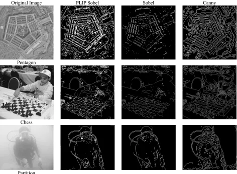
Figure 3 shows the results for several natural images. Again, the first column shows the original, the second column shows the result of the proposed algorithm, and the third and fourth columns shows Sobel and Canny, respectively. These images demonstrate the improved
performance of the PLIP edge detector.
As can be seen from the Pentagon image, Sobel commonly misses edges, most noticeably the diagonal edges in the bottom right corner of the Pentagon. Canny, on the other hand, is able to correctly find the majority of the edges in the Pentagon and surrounding areas. However, one issue with Canny is demonstrated in the bottom left corner; the cars in the parking lot produce a collection of spurious, connected edges that run throughout the parking lot. The result from PLIP Sobel, however, correctly identifies the several rings of the Pentagon, the roadways surrounding it, and does a better job with the parking lot.
Similar results can be seen with the other two images. Chess demonstrates again that Sobel can miss difficult edges, such as the player’s hand or the chair in the background, while Canny picks up spurious edges in the player’s sweatshirt. PLIP Sobel correctly identifies the player’s hand and the objects in the background, while minimizing the response for the player’s sweatshirt to the major folds, such as where he bends his right elbow.
The diver image is a particularly difficult scenario because it is underwater, introducing a large amount of image noise in the form of blurring, glare, contrast reduction, and non-linear effects from the water itself.
Original Image PLIP Sobel Sobel Canny
Pentagon
Chess
Partition
As before, Sobel misses some edges, such as the diver’s snorkel. Canny, on the other hand, places a number of spurious edges throughout the diver’s body where the human eye detects nothing. PLIP Sobel avoids these spurious edges while detecting more objects than classical Sobel, such as the snorkel. Also, it can be seen that PLIP Sobel best detects the difficult criss-crossing tubes from the diving apparatus.
V. EDGE PRESERVING CONTRAST ENHANCEMENT (EPCE) WITH SIMULATION RESULTS AND COMPARISON
In this section, we will present an image enhancement algorithm which makes use of the raw output of an edge detection algorithm. It was shown in [13] that the results of the Edge Preserving Contrast Enhancement (EPCE) algorithm are dependant on the quality of the edge detection algorithm, with more accurate edge detection resulting in better enhanced images. We will show results for the EPCE algorithm using the proposed algorithm as well as other leading algorithms, and compare the results.
A. Edge Preserving Contrast Enhancement (EPCE) Edge Preserving Contrast Enhancement (EPCE) is an algorithm that combines the output of an edge detection algorithm with the original spatial image information to obtain a more robust algorithm that is tunable to perform edge detection or image enhancement [13]. This enhancement algorithm can work with any suitable edge detection algorithm. It uses pre-processing steps to standardize image brightness and several post-processing steps to enhance the edges contained.
The first part of this algorithm is performed on each image pixel and is based on the local mean at each pixel, using the following formula:
2 ( , ) / ( , )
2
( , ) 1
1 x y x y
I x y
eW O
(16)
where I( x, y ) is the output image, IJ( x, y ) is either the V component of the image in HSV color space or the gray scale image, and Ȝ is the local statistic of the image used to adjust the transfer function to the local mean. Finally, where Ȝ is
¸¸
¹
·
¨¨
©
§
N
Qx
M
y
x
C
M
C
y
x
,
)
(
)
(
,
)
(
P
O
(17)
where C is a user selected enhancement parameter, with effective range 0 C < 256,M is the maximum value of the range, and ȝ( x, y ) is the local mean of the image.
After this, a second step is performed to enhance the contrast. This is performed by first applying a high pass filter on the image, then enhance this image. We will call this IEN. For this step, most any common enhancement algorithm can be used. Next, apply edge detection, resulting in the image we will call IED. Finally, the following formula gives the output-enhanced image:
J D)
,
(
)
,
(
)
,
(
,
A
I
x
y
I
x
y
I
x
y
I
F EN EDu
EN(18)
where IF,EN is the output image and A,Į, and Ȗ are user defined operating parameters.
In summary, this algorithm is executed as follows: Input Image
Step 1: Compute image statistics using formula (17) Step 2: Standardize image brightness using formula
(16)
Step 3: Apply high pass filter Step 4: Enhance image to get IEN
Step 5: Apply edge detection to get IED
Step 6: Apply formula (17) to get output image, IF,EN
Output Image
B. Computer Simulations
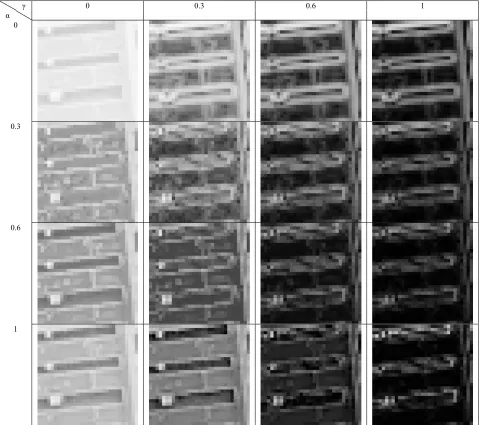
We first demonstrate the use of the EPCE algorithm by showing the effects of the parameters. Figure 4 shows a collection of enhanced images using this algorithm for different values of Ȗ and Į. This shows the effect of the parameters on edge strength and overall image contrast. The effects of these parameters are fairly intuitive from (17);Ȗ controls the edge strength, IED, and Į provides the enhanced contrast, IEN.
The first row of images, with Į = 0, shows how Ȗ
controls the edge strength. When Į = 0, this looks similar to the output of an edge detector, and as Ȗ increases, these edges get stronger. Then, as Į increases, the remainder of the image contrast fills in with the edges.
This also demonstrates the importance of selecting Į
and Ȗ correctly. If Į is set too high, then the important image edges are lost. If Ȗ is set to high, then the image content is lost and only the edges remain. From figure c, it can be seen that the best two images occur at Į = 0.6,
Ȗ = 0, and Į = 1, Ȗ = 0.3. This indicates that the best balance would occur somewhere in the range 0.6 < Į < 1 and 0 < Ȗ < 0.3. We will find that the parameters selected by the measure are Į = 0.6, Ȗ = 0.2; which are the parameters used for the Pentagon image in figure 5.
In order to evaluate the proposed edge detection algorithm, we compare the results of the EPCE algorithm using the proposed edge detector to those using the other leading edge detection algorithms. We perform the comparison for a collection of images using the Logarithmic AME measure as the basis for comparison.
cell phone instead of with a tripod mounted camera with dedicated lighting.
The enhanced images in figure 5 show the improved performance of the EPCE algorithm using the proposed edge detection method over the other edge detection methods. The Pentagon image has many diagonal images. As the proposed algorithm is better able to detect these edges, this gives a sharper image with better contrast. The diver image shows the strength of the proposed algorithm is difficult scenarios, giving a sharper image than the other edge detection algorithms. This enhanced image, in figure 5.f, clearly shows all of the diver’s equipment and has good contrast between the diver and the background. For the wall image, the other two edge detection algorithms emphasize some of the noise added by the lower quality digitization inherent in cell phone images, lowering the enhanced images’ quality. This is not the case with the results using the proposed algorithm. Also, for all three images, the Logarithmic AME values of the enhanced images using
the proposed method are higher than those for the other methods, further demonstrating the high performance of the proposed edge detection method.
Table I shows Logarithmic AME values for a collection of other images as well, to demonstrate the robustness of the algorithm. It can be seen that, for a wide variety of images, the proposed algorithm outperforms the other methods on the basis of the Logarithmic AME measure. This includes common test images, more difficult images, and cell phone camera images.
From Table I, Pentagon, clock, and Lena are all well known common test images. Highway is a foggy image of traffic on a highway, and diver, turtle, and fish are all underwater images. Wall, cave, and faces are all camera phone images, captured with the same camera phone as the wall image. For every image, the output of the EPCE algorithm with the proposed algorithm scores higher on the Logarithmic AME than for the other two algorithms. This shows the robustness of the proposed algorithm for a
Ȗ Į
0 0.3 0.6 1
0
0.3
0.6
1
TABLE I.
LOGARITHMIC AME VALUES FOR EPCE ALGORITHM
Image Proposed Algorithm
Sobel Canny
Pentagon 71.8045 62.8536 61.4667 Clock 154.8656 134.1348 132.3618
Lena 138.1151 122.4565 121.8269 Diver 17.3682 16.9127 16.9279 Highway 284.0660 278.4828 277.2733
Turtle 143.1683 142.3334 140.9727 Fish 186.2207 180.3749 180.9412 Wall 385.6494 367.4256 366.1753 Cave 169.5164 167.3053 167.2748 Faces 423.3307 418.6522 418.3904
wide variety of simple and more difficult images.
VI. CONCLUSION
In this paper, a PLIP based edge detection method was presented. This method incorporates the LIP contrast estimator with the LIP Sobel method and the improvements of PLIP. It was shown that this method outperforms the Sobel and Canny edge detector on the basis of Pratt’s Figure of Merit for synthetic images and
on the basis of visual inspection for natural images. The application of this new edge detection algorithm for image enhancement was also demonstrated. An enhancement method which is highly dependent on edge detection results, Edge Preserving Contrast Enhancement (EPCE), was utilized in conjunction with the edge detectors presented. It was shown that, using the Parameterized LIP Sobel Edge Detection method, it is possible to achieve better image enhancement using the EPCE algorithm. Future work will include developing new PLIP based edge detection methods which can further improve the performance of the EPCE algorithm.
REFERENCES
[1] H. T. Tan, S. B. Gelfand, and E. J. Delp, “A Comparative Cost Function Approach to Edge Detection, IEEE Tran.
Systems, Man, and Cybernetics, 19(6), pp. 1337—1349,
December, 1989.
[2] P. J. Besl and R. C. Jain, “Three-Dimensional Object Recognition,” Computing Surveys, 17(1), pp.75—145, March 1985.
[3] A. Rosenfeld and A. C. Kak, Digital Image Processing, New York: Academic Press, 1982.
[4] P. H. Eichel, D. J. Delp, “Quantitative Analysis of a Moment-Based Edge Operator,” IEEE Tran. Systems,
Original Image Proposed Method Sobel Canny
Pentagon (a)
LogAME = 71.8045 (b)
LogAME = 62.8536 (c)
LogAME = 61.4667 (d)
Diver (e)
LogAME = 17.3682 (f)
LogAME = 16.9127 (g)
LogAME = 16.9279 (h)
Wall (i)
LogAME = 385.6494 (j)
LogAME = 367.4256 (k)
LogAME = 366.1753 (l)
Figure 5. Comparative results of EPCE using all three edge detection algorithms, shows that the proposed algorithm outperforms Sobel and Canny both on the basis of the measure and visual inspection; (a-d)Original image and enhanced images for Pentagon, (e-h)Original image and enhanced images for Diver, (i-l)Original image and enhanced images for Wall; this shows that the proposed method outperforms the other methods on the basis
Man, and Cybernetics, 20(1), pp. 59—66, January/February 1990.
[5] J. Canny, “A Computational Approach to Edge Detection,” IEEE Tran. Pattern Analysis and Machine Intelligence, 8(6), pp. 679—698, November, 1986.
[6] P. Bao, L. Zhang, and X. Wu, “Canny Edge Detection Enhancement by Scale Multiplication,” IEEE Tran. Pattern Analysis and Machine Intelligence, 27(9), pp. 1485—1490, September, 2005.
[7] V. S. Nalwa and T. O. Binford, “On Detecting Edges,” IEEE Tran. Pattern Analysis and Machine Intelligence, 8(6), pp. 699—714, November, 1986.
[8] R. M. Haralick, “Digital Step Edges from Zero Crossings of Second Directional Derivatives,” IEEE Tran. Pattern Analysis and Machine Intelligence, 6(1), pp. 58—68, January, 1984.
[9] M. Jourlin, J. C. Pinoli, “Logarithmic Image Processing; The Mathematical and Physical Framework for the Representation and Processing of Transmitted Images,”
Advances in Imaging and Electron Physics, 115, pp. 129—196, 2001.
[10] G. Deng, L. W. Cahill, “The Logarithmic Image Processing Model and Its Applications,” in Conf. Record 1993 Asilomar Conference on Signals, Systems, and Computers, volume 2, pp. 1047—1051, 1993.
[11] K. Panetta, E. J. Wharton, S. S. Agaian, “Parameterization of Logarithmic Image Processing Models,” IEEE Tran. Systems, Man, and Cybernetics, Part A: Systems and Humans, submitted for publication January 2007.
[12] W. K. Pratt, Digital Image Processing, New York: John Wiley & Sons, 1991.
[13] K. Panetta, E. J. Wharton, S. S. Agaian, “Human Visual System based Image Enhancement and Logarithmic Contrast Measure,” IEEE Tran. Systems, Man, and Cybernetics, Part B: Cybernetics, submitted for publication February 2007.
[14] S. Agaian, B. Silver, and K. Panetta, “Transform Coefficient Histogram Based Image Enhancement Algorithms Using Contrast Entropy,” IEEE Tran. Image Processing, 16(3), pp. 751—758, 2007.
[15] A. Beghdadi and A. L. Negrate, “Contrast Enhancement Technique Based on Local Detection of Edges,” Computer Visualization of Graphic Image Processes, 46, pp. 162— 274, 1989.
[16] J. K. Kim, J. M. Park, K. S. Song, H. W. Park, “Adaptive Mammographic Image Enhancement using First Derivative and Local Statistics,” IEEE Tran. Medical Imaging, 16, pp. 495—502, 1989.
[17] W. M. Morrow, R. B. Paranjape, R. M. Rangayyan, and J. E. L. Desautels, “Region-Based Contrast Enhancement of Mammograms,” IEEE Tran. Medical Imaging, 11(3), pp. 392—406, 1992.
[18] Gregory Beylkin, “Discrete Radon Transform,” IEEE Tran. Acoustics, Speech, and Signal Processing, 35(2), pp. 162—172, 1987.
Karen Panetta received the B. S. degree in computer engineering from Boston University, Boston, MA, and the M. S. and Ph.D. degrees in electrical engineering from Northeastern University, Boston.
She is the Chief Research Scientist for BA Logix Inc. She is also a Professor of Electrical and Computer Engineering at Tufts University. Dr. Panetta is the IEEE Director of Women in Engineering and is the Editor-in-Chief of the IEEE Women in Engineering Magazine. She is a Fellow of the IEEE.
Eric J. Wharton was born July 24, 1984. He has a B.S. in computer engineering and the M.S. degree in electrical engineering from Tufts University in Medford, MA
He was a Research Assistant in SIMLAB at Tufts University under the advisement of Dr. Karen Panetta. His current research interests include image and signal processing, specifically developing performance metrics.
Mr. Wharton is a student member of the IEEE and SPIE, and is a member of Eta Kappa Nu (HKN) and Tau Beta Pi (TBP).
Sos Agaian received the M. S. degree (summa cum laude) in mathematics and mechanics from Yerevan State University, Yerevan, Armenia, the Ph.D. degree in mathamatics and physics and the Doctor of Engineering Sciences (equivalent to the US Doctor of Electrical and Computer Engineering) degree from the Academy of Sciences of the USSR, Moscor, Russia, and the Diploma in computer science (equivalent ot the US Ph.D. Degree in computer science) from the Supreme Attestation Board of the USSR, Moscow.
He is currently the Peter T. Flawn Distinguished Professor with the College of Engineering, University of Texas at San Antonio, San Antonio, and an Adjunct Professor with the Department of Electrical and Computer Engineering, Tufts University, Medford, MA. He is the author of more than 350 scientific papers and four books and is the holder of 13 patents. He is an Associate Editor for the Journal of Real-Time Imaging and the Journal of Pattern Recognition and Image Analysis. His current research interests include signal/image processing and transmission, multimedia security, digital forensics, vision networks, and mobile imaging and secure communication.