INTERNATIONAL JOURNAL OF ENGINEERING SCIENCES &
MANAGEMENT
REVIEW PAPER ON SMART ANTENNA SYSTEM IN DIFFERENT ASPECT OF
WIRELESS NETWORK
Harish Sukumar
1, Manish Gurjar
2Department of Electronics and Communication Engineering (Digital Communication)
TIT COLLEGE BHOPAL (M.P.), India
[email protected]
1Abstract
Smart Antenna system is the One of the most rapidly developing areas of communications. The use of smart antennas in mobile communications that enhances the capabilities of the mobile and cellular System such a faster bit rate, multi-use interference, space division multiplexing (SDMA), increase in range, multipath mitigation, and reduction of errors due to multi path fading and w ith one great advantage that is a very high security. The signal that is been transmitted by a smart antenna cannot be tracked or received by any other antenna, thus ensuring a very high security of the data transmitted. We study the required algorithms that are need for the beam forming in the antenna patters. Smart antenna systems have been long predicted to provide much better performance than existing antennas in terms of power consumption, user capacity and noise suppression these advantages are due to the antenna array and the performance of digital signal processing techniques used in the system. Direction-of-arrival (DOA) algorithm plays a crucial role in smart antenna system to ensure that the antenna array is able to estimate the direction of the incoming signal and thus, with the aid of adaptive beam forming, to point the array beam towards the estimated direction.
Keywords: Smart antenna, DOA, Beam forming, switched beam, adaptive array.
I.
INTRODUCTION
A smart antenna is an array of antenna elements connected to a digital signal processor. Such a configuration dramatically enhances the capacity of a wireless link through a combination of diversity gain, array gain, and interference suppression. as the demand for wireless communications constantly grows, the need arises for better coverage, improved capacity, and higher transmission quality. Thus, a more efficient use of the radio spectrum is required. Smart antenna systems are capable of efficiently utilizing the radio spectrum and promise an effective solution to the present wireless system problems while achieving reliable and robust high speed high-data-rate transmission. Using beam forming algorithms the weight of antenna arrays can be adjusted to form certain amount of adaptive beam to track corresponding users automatically and at the same time to minimize interference arising from other users by introducing nulls in their directions.
II.
FUNCTIONS OF SMART
ANTENNA
A. Direction of Arrival Estimation
The smart antenna estimates the direction of arrival of the signal, using techniques such as Multiple Signal Classification, estimation of signal parameters via rotational
invariance techniques (ESPRIT) algorithms, Matrix Pencil method or one of their derivatives. They involve finding a spatial spectrum of the antenna/sensor array, and calculating the DOA from the peaks of this spectrum. These calculations are computationally intensive. Matrix Pencil is very efficient in case of real time systems, and under the correlated sources.
B. Beam forming
receiving weak signals. Thirdly, signal interference is reduced due to the rejection of undesired signals. For the uplink case of transmitting from the antenna array to a mobile telephone, system interference is reduced since the signal is only transmitted in the look direction. A digital beam former is one that operates in the digital domain. Traditionally, beam formers were implemented in analog; the weights were determined and applied to the antenna inputs via analog circuitry. With digital beam forming, the antenna signals are individually translated from Radio Frequencies (RF) to Intermediate Frequencies (IF), digitized and then down-converted to base-band I and Q components. A beam forming algorithm implemented on one or more digital signal processors then processes I and Q components to determine a set of weights for the input signals. The input signals are then multiplied by the weights and summed to output the signal of interest (SOI).
III.
TYPES OF SMART ANTENNA
SYSTEMS
There are basically two approaches to implement antennas that dynamically change their antenna pattern to mitigate interference and multipath affects while increasing coverage and range.
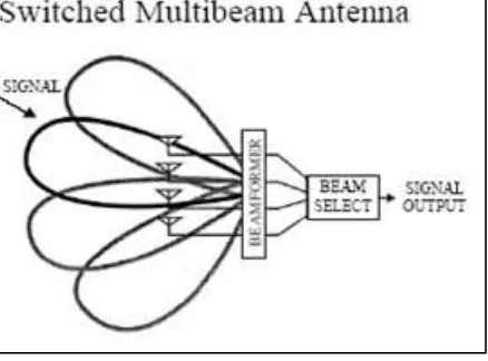
A. Switched Multi-beam Antenna
The Switched beam approach is simpler compared to the fully adaptive approach. It provides a considerable increase in network capacity when compared to traditional Omni directional antenna systems or sector-based systems. In this approach, an antenna array generates overlapping beams that cover the surrounding area. When an incoming signal is detected, the base station determines the beam that is best aligned in the signal-of-interest direction and then switches to that beam.
Fig. 1: Switched Multibeam Antenna
B. Adaptive Arrays
The Adaptive array system is the “smarter” of the two approaches. This system tracks the mobile user continuously by steering the main beam towards the user and at the same time forming nulls in the directions of the interfering signal. Like switched beam systems, they also incorporate arrays. Typically, the received signal from each of the spatially distributed antenna elements is multiplied by a weight. The weights are complex in nature and adjust the amplitude and phase. These signals are combined to yield the array output. These complex weights are computed by a complicated adaptive algorithm, which is pre-programmed into the digital signal-processing unit that manages the signal radiated by the base station.
Fig.2: Adaptive Antenna Array
IV.
Adaptive Beam forming & Algorithms
The convergence speed of the LMS algorithm depends on the Eigen values of the array correlation matrix[11]. In an environment giving an array correlation matrix with large Eigen value spread the algorithm converges with a slow speed. This problem is solved with the RLS [5] algorithm by replacing the gradient step size with a gain matrix ΛR (n). The RLS algorithm does not require any matrix inversion computations as the inverse correlation matrix is computed directly [6]. It requires reference signal and correlation matrix information. An important feature of the recursive least square algorithm is that its rate convergence is typically an order of magnitude faster than that of the simple least square [6].
V.
APPLICATIONS
OF
SMART
ANTENNA
Space-time processor (’smart ‘antenna’) is capable of forming transmit/receive beams towards the mobile of interest. At the same time it is possible to place spatial nulls in the direction of unwanted interferences. This capability can be used to improve the performance of a mobile communication system.
A. Increased antenna gain
The ’smart’ antenna forms, transmit and receive beams. Therefore, the ’smart’ antenna has a higher gain than a conventional Omni-directional antenna. The higher gain can be used to either increase the effective coverage, or to increase the receiver sensitivity, which in turn can be exploited to reduce transmit power and electromagnetic radiation in the network.
B. Decreased inter-symbol-interference (ISI) Multipath propagation in mobile radio environments leads to ISI. Using transmits and received beams that are directed towards the mobile of interest reduce the amount of Multipath and ISI.
C. Decreased co-channel-interference (CCI) Smart antenna transmitters emit less interference by only sending RF power in the desired directions. Furthermore, ’smart’ antenna receivers can reject interference by looking only in the direction of the desired source. Consequently ’smart’ antennas are capable of decreasing CCI. A significantly reduced CCI can be taken advantage of by Spatial Division Multiple Access (SDMA).
VI.
SMART
ANTENNA
RELATED
WORKS
Several researches have been done in this field such as follows.
A. “Microprocessor controlled phased array system for Smart Electronic Phase Control”, in this paper, author [1] present a microprocessor controlled phased array system which can point in a desired direction as in conventional phased array systems. The additional feature is that even if the source changes position relative to the original beam direction, microprocessor controlled system checks for the maximum signal direction regularly and changes the necessary phase angles of the phase shifters to point in the incoming signal direction. This is realized by continues detecting and tracking functions. Details of the design, choice of phase detectors and implementation using a linear and planar arrays will be presented a smart phased array system is presented which can be programmed to continuously monitor the incoming signal direction and point the main beam automatically in that direction without losing communication. Once the right phase shifters are chosen, corresponding digital system is designed including the necessary number of DACs. The microprocessor is then programmed to satisfy the functionality of the system.
C. “The WWRF and SAS Technology”, in this paper author [3]particular, identify and scope research issues relevant to future mobile and wireless communications, including pre-regulatory impact assessments and invite worldwide participation. As such, the Forum provides a global platform for discussion of results, exchange of views to initiate global cooperation towards systems beyond 3G. In particular, smart antenna technology has become one of the most dominant technologies for future wireless systems. This paper gives an overview of the WWRF and smart antenna technologies being developed within the WWRF.
D. “MLA for High Frequency RFID Smart Shelf Application” in this paper author [4] has presented a patent-pending multi loop antenna for HF (13.56MHz) RFID smart shelf applications. The proposed antenna prototype has been able to generate magnetic field with uniform magnitude for a larger interrogation region. In addition, the low profile structure makes it very easy for implementation hence; the system installation cost has been reduced significantly. The patent-pending multi-loop antenna has been used for RFID smart shelves which are implemented in library for book management with achieved detection accuracy of 95-100%.
E. “RC and EI to Smart Antenna” in this Research author [5] has actual working conditions influence to communication ability with common and similar smart antenna. Methods: Experimental research, data comparison and the results analysis comprehensively. Test received and sent data-packets successful ratio, and it’s reception intensity with antenna in USB network device in Windows 98 system, under AP (infra- structure) mode with wireless broadband routers at several channels. It is greatly changing the similar smart antenna position indoors of crowd residential area, under 1 to most several BSs at the same channel. Results: The reception intensity is 70~76%, even over90% out of the door, the successful reception packets 14~20%,even below 10%; sending packets below 10% even 2% between wireless router and adapter only Conclusion: It is stronger than commons in the field and less penetrating through impediments that main-directional pattern self-fit antenna for its reception and sending. Synchronous uplink for smart one keeps unblocked communication to overcome wave front distortion and multipath interference. The reflector is very effectual method strong signal for common antenna, but not suitable for smart one. Unidirectional antenna concentrates energy for long distance point-to-point fixed communication and weakening signal, so that it suits and penetrates through multi impediments.
In this Paper author[6] explored methods for forming an Over The Horizon (OTH) communications link of Wireless Sensor Networks (WSNs) by enabling each WSN to act as a smart antenna array. Each WSN was modeled as a uniformly distributed random array of sensors nodes. An element random planar array, comparable to a 36 element periodic planar array of similar size, was simulated to demonstrate the search capability. Methods for establishing the OTH communications link via beam forming and direct sequence spread spectrum Space Division Multiple Access (SDMA) were presented and modeled using MATLAB. Methods for forming a search beam for a transmitting WSN and determining the direction of arrival of the received beam for a receiving WSN were presented.
F. “Error Estimation in AAO (Angle of Arrival) in smart Antenna” in this Paper author [10] provides comparative analysis and simulation of angle of arrival (AOA) estimation, and estimate error in AOA estimation. Relative results are useful for achieving optimal performance in smart antenna design rapidly growing demand in mobile communication system required technology which will provide minimum errors and maximize SNR in a particular angle/direction. Smart antenna has a system for directed a interference from
undesired angle/direction. MUSIC (Multiple Signal Classification) has capability to estimate number of signals in an array and angle/direction of arrival of desired signal. ESPRIT (Estimation of Signal Parameters via Rotational Invariance Techniques) is used for the estimation of direction of arrival of multiple sets of identical doublets, provides parallel processing. Describes that ESPRIT have lower noise/errors than MUSIC, describes the facts that doublet array performance is better than normal array.
G. “Four-port beam reconfigurable antenna array for pattern diversity system” in this paper author [11] this study investigates a practical design for a switched beam planar antenna that can be implemented as a compact, low-cost switchable and/or reconfigurable beam antenna array. The antenna consists of a four-port antenna array, which is based on L-shaped quarter-wavelength slot antenna elements. This type of antenna array is a planar structure and its maximum directional radiation beam pattern presents in an azimuth plane covering 3608. The antenna array operates based on the ‘ON’ or ‘OFF’ states of PIN diodes in each individual slot antenna element and the combined signals from the four-port output.
beam forming Algorithm RLS have been analyzed on a smart antenna system. It was noticed that increasing the number of elements of the antenna array ensures better performance. Conventionally, the LMS adaptive algorithm has been used to update the combining weights of adaptive antenna array. In an environment yielding an array correlation matrix with large Eigen values spread the algorithm converges with a slow speed [14]. This problem is solved with the RLS algorithm by replacing the gradient step size _ with a gain matrix. It was noticed that increasing the number of elements of the antenna array ensures better performance. Also conclude that the optimum spacing beam between the elements is half wave length.
J. Analysis of DOA Estimation for Directional and Isotropic Antenna Arrays. in this paper[15] A comparison analysis between two different types of antenna arrays in direction of-arrival (DOA) estimation is presented. This study was undertaken to point out any difference in the process of DOA estimation between isotropic and directional antenna array. To the best of our knowledge, there is no previous work that analyzed the DOA estimation between these two antenna arrays. The approach taken was to estimate all predetermined angle-of-arrival (AOA) correctly by using MUSIC, a spectral-based DOA algorithm. Results obtained show that, to perform the DOA estimation, isotropic antenna array depends entirely on DOA algorithm, whereas directional antenna array required both the DOA algorithm and the position of the main beam at any instant. This work concludes that, in practical application.
VII.
CONCLUSION
A brief overview study of smart antenna in different aspect in design , application and various DOA and beam forming algorithm analysis are discussed .This field is attracting Considerable research attention in all of these areas. There are further investigation especially in the area of small size and low cost and better performance in 2.4 to 2.8 GHz wireless communication range. A compact low-cost low-power smart antenna has been developed. To reduce the cost and power consumption.
REFERENCES
[1] G. M. Rebeiz, G.-L. Tan, and J. S. Hayden, "RF MEMS phase shifters: design and applications," Microwave Magazine, IEEE, vol. 3, pp. 72-81, 2002.
[2] Martin Wagner, Uhland Goebel, Jan Hesselbarth, Mischa Graeni, Peter Nuechter, “Multi-Band Polarization- Versatile Array Antenna
for Smart Antenna Applications in Cellular Systems”, IEEE 2004.
[3] Pieter van Rooyen, AngelikiAlexiou, “The Wireless World
Research Forum and Future Smart Antenna Technology”, IEEE 2006.
[4] Xianming Qing, ZhiNing Chen, AilianCai, “Multi-loop Antenna
for High Frequency RFID Smart Shelf Application”, IEEE 2007. [5] Jianren Hu, Huibin Qin, “Reception Condition And Environment
Influence to Smart Antenna”, Hangzhou Oianzi University, Hangzhou 310037, 2007
[6] Y.-W. Hong, W.J. Huang, F.-H.Chiu, and C.-C. Jay Kuo,
“Cooperative Communications in Resource-Constrained Wireless Networks,” IEEE Signal Processing Magazine, Vol. 24, Issue 3, pp 47-57, May 2007.
[7] Waiyieleong “Angle of Arrival Estimation:
Beamformer-BasedSmartAntennas”, 978-1-4244-1718-6/08, pp.1593-1598, 2008 IEEE
[8] Susmita das, “Smart Antenna Design for Wireless
Communication using Adaptive Beam-forming Approach”,
10.1109/TENCON.2008.4766732, 2009 IEEE.
[9]V.-A. Nguyen, M.-H.Jeong M,T. Dao ,S.-O. Park “Four-port
beam reconfigurable antenna array for pattern diversity system”
Published in IET Microwaves, Antennas & Propagation Received on 21st December 2011 Revised on 24th May 2012 doi: 10.1049/iet-map.2011.0606.
[10]Khyati R. Zalawadia, Twinkle V. Doshi,Dr U. D Dalal “Adaptive Beam Former Design using RLSAlgorithm for Smart Antenna System” 2011 International Conference on Computational Intelligence and Communication Systems.
[11] Susmita Das, “Smart Antenna Design for Wireless
Communication using Adaptive Beam-forming Approach” Tencon- 2008 IEEE Region 10 conference.
[12] A. Cidronali, S. Maddio, G. Giorgetti, and G. Manes, "Analysis and Performance of a Smart Antenna for 2.45-GHz Single-Anchor Indoor Positioning," Microwave Theory and Techniques, IEEE Transactions on, vol. 58, pp. 21-31, 2010.
[13] RahmatSanudin, Nurul H. Noordin, Ahmed O. El-Rayis, Nakul Haridas, Ahmet T. Erdogan and TughrulArslan “Analysis of DOA