Analysis Of Patch Antenna With Defected Ground
Structure For Wireless Applications
M.Sumathi, P.Chitra , K.Srilatha
Abstract : Microstrip fix receiving wire finds a superior decision in remote correspondences in view of their less cost, light weight and simplicity of creation. Small size wide band reception apparatuses are of awesome request in future advances with the fast development of remote correspondence innovation. Notwithstanding innate impediment like thin transfer speed and low pick up, microstrip fix receiving wires have various preferences. Be that as it may, different strategies have been examined for the improvement of both transfer speed and gain. This paper proposes a novel outline with deserted ground structure so as to get better data transfer capacity. The structure is designed at 8.5 GHz using FR4-epoxy as substrate material that has relative permittivity 4.4 and loss tangent 0.02. HFSS (High Frequency Structure Simulator) software is used for simulating the proposed design. This antenna obtained the return loss -12.87 dB, -14.36 dB at 5.5 GHz and 10.5 GHz with a VSWR of less than 2. In order to enhance the bandwidth of the antenna, defected partial ground has been used which truncate at the edges so, that bandwidth of more than 1 GHz has been achieved at both resonating frequencies. Gain of 4.24 dB and 6.27 dB has been obtained at 5.5 GHz and 10.5 GHz. The efficiency of antenna is also found to be good and proposed design has suitable characteristics so that it can be used in WiMax and Radar applications.
Keywords: Patch antenna, Microstrip, FR4-epoxy, HFSS, VSWR, DGS
—————————— ——————————
I INTRODUCTION
The quick headway in microwave and remote correspondence has pulled in the interests in microstrip receiving wires. With the boundless multiplication of remote correspondence innovation as of late, the interest for smaller, low profile, simplicity of similarity with microwave circuits and less cost has expanded fundamentally [17]. Be that as it may, despite these favorable circumstances microstrip radio wires experiences constraints, for example, limit data transfer capacity and low pick up. To maintain a strategic distance from utilization of two separate receiving wires for two recurrence groups and to satisfy the request of driving business sector there is a need to build up the double band radio wires. Numerous outlines are accounted for in writing, for various correspondence groups, which utilizes diverse procedures, for example, opening, abandoned ground structure and so on to upgrade the execution of Microstrip fix radio wires likewise assortments of fix structures are planned. Presently a day defected ground structure (DGS) microstrip fix receiving wires have been quickly created for multi-band and wide band in wideband correspondence frameworks. M.HaroonTaria et.al recommended that the prerequisite of fast remote neighborhood (IEEE 802.11a standard) and other correspondence systems.Bandwidth increments because of bigger width of microstrip antenna. [7]. In recent years, specialists have been examined distinctive strategies to upgrade the transfer speed. It is watched that proficiency of radio wire get increments by expanding transfer speed and pick up diminishes in like manner. J.A. Ansari et.al portrayed that substrate thickness and openings length have huge impact on recurrence proportion [11]. Garima et.al suggested that by expanding the measure of jewel molded opening compelling range of circle get abatements and fix current increments. So that, impedance data transmission and pick up of radio wire get increments.
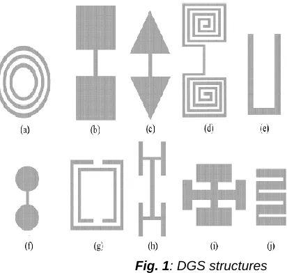
Enhanced transfer speed is of 13.58% for C-band application [12]. C. J. Wang et.al introduced that a Z-like opening get stacked on a fix which increments full recurrence as number of spaces increments without expanding involved space territory [14]. Srijita Chakraborty et.al watched that by changing crisscross formed DGS, reception apparatus reverberate at Bluetooth, WiMAX and IMT groups individually [17]. A.K.Arya et.al proposed distinctive absconded ground structures in detail. It has been watched that from single Skew-F molded deformity in ground plane,the recurrence proportion is diminishes by expanding the length of center arm of F. It has been watched that great impedance coordinating is accomplished by expanding the quantity of openings [18]. U. Chakraborty et.al portrayed that a double band microstrip fix reception apparatus for WLAN application is dependable to move down the resounding recurrence to bring down esteems. Opening impedance is specifically corresponding to length of the space is step by step expanded [19]. Regular microstrip radio wires had a few constraints, that is, single working recurrence, low impedance transmission capacity, low increase, bigger size, and polarization issues. There are number of methods which have been accounted for upgrading the parameters of traditional microstrip radio wires, that is, utilizing stacking, diverse sustaining strategies, Frequency Selective Surfaces (FSS), Electromagnetic Band Gap (EBG), Photonic Band Gap (PBG), Metamaterial, et cetera. Microwave segment with Defected Ground Structure (DGS) has been picked up ubiquity among every one of the strategies detailed for improving the parameters because of its basic plan. Scratched openings or deformities on the ground plane of microstrip circuits are alluded to as Defected Ground Structure. Single or various deformities on the ground plane might be considered as DGS. At first DGS was accounted for channels underneath the microstrip line. DGS has been utilized underneath the microstrip line to accomplish band-stop qualities and to smother higher mode sounds and common coupling. After effective usage of DGS in the field of channels, these days DGS shown in Fig.1 is popular broadly for different applications. The Rare side DGS Structure is in Fig.3. Minimal effort, superior, conservative size, wideband, and low profile radio wires regularly meet the stringent prerequisites of present day remote correspondence ___________________________
Department of ECE, Sathyabama Institute of Science and Technology, Chennai, India
427 frameworks. Present day correspondence requests the
accessibility of productive, smaller, and versatile gadgets that can be worked at high information rates and at low flag powers. Scientists have been working towards improvement and headway of RF front finishes to meet the most recent prerequisites. The goal of the venture is to outline double band micro strip fix reception apparatus for remote applications by utilizing abandoned ground structure (DGS).To dissect execution of radio wire in schematic. The fix that is utilized for the proposed configuration is combinational 'E' and 'U' fix so as to acquire double recurrence band. To execute receiving wire progressively.
Fig. 1: DGS structures
II RELATED WORK
ChiragGarg, Magandeep Kaur has completed a concise survey on DGS and portrayed that Electromagnetic band gap (EBG) or on the other hand called photonic band hole (PBG) structures have been alluring to acquire the capacity of undesirable recurrence dismissal and circuit measure diminishment. Looks into on the PBG had been initially done in the optical recurrence. As of late, there has been an expanding enthusiasm for microwave and millimeter wave utilizations of PBG circuits. This paper displays an instructional exercise review of the new approach for planning smaller channels like low pass, band stop and band pass having a few favorable circumstances than Photonic Band Gap (PBG). This system is named as Defected Ground Structure (DGS). The fundamental originations and transmission qualities with identical circuit models of assortments of DGS units are introduced. Finally, the primary uses of DGS in microwave innovation field have been portrayed. AnjuVerma, Debajit De, Nanda, Tripathy actualized a novel fix radio wire outline for double band. They have proposed a Slotted Microstrip Patch Antenna shown in Fig.2 with a Defected Ground Here, we have coordinated the idea of DGS and Slotted Patch Antenna keeping in mind the end goal to get upgraded transmission capacity and pick up The proposed radio wire comprises of a microstrip bolstered opened rectangular fix with E-molded cut in the ground plane. The execution of this receiving wire is talked about and broke down with execution of this radio wire is examined and various spaces. The varieties in Return Loss (S11), Radiation Pattern and Gain The reception apparatus demonstrates a double band attributes having a return loss of beneath - 20 dB
reenacted comes about for two recurrence groups. R. Kiruthika, Dr. T. Shanmuganantham, Rupak Kumar Gupta executed An opened fan molded microstrip fix receiving wire with three working frequencies for radar application is displayed. The plan display is made to resound at three frequencies in Xband. The X-band recurrence go falls between 8 to 12 Gigahertz and are broadly utilized as a part of radar applications. The dielectric substrate material utilized by the reception apparatus is of minimal effort FR4 (Flame Retardant – Grade 4) Epoxy. To enhance the reception apparatus execution, the radio wire configuration is incorporated with Defected Ground Structure (DGS). The Ansoft High Frequency Structural Simulator (HFSS) Version 12 programming is utilized to break down the outcomes. With 9.93 GHz, 10.81 GHz and 11.56 GHz as the full frequencies, an arrival loss of - 18.47 dB, - 42.23 dB and - 19.74 dB are acquired with 470 MHz, 590 MHz and 420 MHz as the data transmission separately. The parameters like pick up, transfer speed, return misfortune and directivity are talked about in the paper. FitriYuliZulkifli, Susy Tri Lomorti, EkoTjiptoRahardjo executed a Novel isosceles-triangular deserted ground structure (DGS) is actualized on Triangular Patch Linear Array microstrip radio wires to suppress surface waves and enhance the outline. The radiation execution of the receiving wire is described by the measurement of the DGS and by finding the DGS at particular position which is discovered tentatively. Estimated comes about demonstrates that the reception apparatus with DGS can enhance impedance coordinating with better return loss of - 45.48 dB from - 30.33 dB, data transfer capacity improvement (2.87 MHz), pick up upgrade upto 0.5 dB and smother cross polarization. R.Er-rebyiy, J.Zbitou1, A.Tajmouati, M.Latrach, A.Errkik, L.ElAbdellaoui talked about the idea of Defected Ground Structures (DGS) has been created to enhance the qualities of numerous microwave gadgets. For this reason the DGS is additionally utilized as a part of the microstrip radio wire for a few favorable circumstances, for example, reception apparatus estimate lessening, common coupling diminishment in receiving wire exhibits and so on... In this paper the abandoned ground structure (DGS) has been utilized to scale down a microstrip fix receiving wire and to move the reverberation recurrence from an underlying estimation of 10 GHz to a last and incentive at 3.5 GHz, with no adjustment in the measurements of the first microstrip fix reception apparatus. This receiving wire is outlined on a FR-4 substrate with dielectric consistent 4.4 and thickness 1.6 mm and its size is 27 X 30 mm2. The receiving wire is composed, streamlined, and scaled down by utilizing CST MW. R. Kiruthika, Rupak Kumar Gupta actualized a Microstrip Patch reception apparatus with two working frequencies for radar application is displayed. The reception apparatus is demonstrated to resound at two frequencies in X-band. The X-band recurrence extend lies between 8 to 12 Gigahertz and are for the most part utilized as a part of radar applications. The outline comprises of Defected Ground Structure (DGS) gave to enhance the recieving wire execution. The dielectric substrate utilized by the radio wire is of minimal effort FR4 (Flame Retardant) Epoxy. The Ansoft High Frequency Structural Simulator (HFSS) Version 12 programming is utilized to break down the outcomes. The parameters like pick up, return misfortune, directivity and transfer speed are examined in the paper. With 9.19 GHz and 10.82 GHz as the resounding frequencies, an arrival loss of - 22.91 dB and -
40.99 dB is acquired with 540 MHz and 1600 MHz as the data transmission separately.
III EXISITNG SYSTEM
In existing framework, have proposed an opened fix Antenna with a Defected Ground structure, they have presented the idea of DGS fix. Radio wire keeping in mind the end goal to get upgraded transfer speed and gain.The proposed receiving wire comprise of a microstrip encouraged opened rectangular fix with
Table 1: Design Specification of MSPA
E-formed cut in the ground plane. The execution of this radio wire is talked about and examined with the varieties in the fix width and number of openings. The varieties in the arrival misfortune (s11), Radiation example and Gain of the planned reception apparatus are examined for various contextual investigations. The radio wire demonstrates a double band attributes having an arrival loss of beneath - 20 dB at 3.2 – 3.5 GHz and underneath - 10 db at 5.6 - 5.8 GHz, which is appropriate for IEEE 802.16 WiMAX and IEEE11p WLAN applications. Material they have utilized as dielectric medium is the Roger RO4003. The substrate tallness is 1mm.
3.1 DRAWBACKS OF EXISTING WORK
They planned a radio wire which is primarily engaged keeping data transmission and Gain.
They outlined a receiving wire with less pick up and less application recurrence groups.
The outline of the reception apparatus is complicated plan.
The manufacture of the receiving wire is Expensive
IV PROPOSED WORK
Proposed work manages the plan of 'E' and 'U' formed combinational fix with deserted ground structure. E and U combinational fix is utilized to get double recurrence band. Investigation with different deserted ground structures to acquire better execution attributes is done. For different parameters like return misfortune, pick up, transmission capacity and radiation design ,the proposed configuration is dissected.
4.1 DESIGN PARAMETERS AND SPECIFICATION OF PATCH ANTENNA
The proposed double band fix exhibit receiving wire is planned and mimicked over the HFSS programming. The plan structure and parameters are recorded beneath in table 1. The proposed microstrip fix cluster radio wire is worked over a scope of 5-6 GHz. The thunderous recurrence is 5.56 GHz with the utilization of regular remote correspondence frameworks. The FR 4 Substrate material is utilized with dielectric consistent of 4.4 and misfortune digression of 0.00018. As like a plan strategy the proposed fix exhibit reception apparatus is reverberate at 30 GHz and gets the most extreme wanted yield. The sustain width is 2mm.
SL.No. Parameters Values 1 Patch dimension (L*W) 45*45
2 Feed length (L) 0.3mm
3 Feed width (W) 2mm
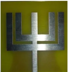
429 Fig. 2: Front side of Patch antenna
Fig.3: Rare side DGS Structure
V RESULTS AND DISCUSSION
5.1 RETURN LOSS
The down to earth circuit acknowledgment endures with the befuddle between the accessible source control and the power conveyed. This is known as return misfortune. Return misfortune = - 20log (Гin) of the radio wire is gotten as - 21 dB at 5.71 GHz, - 11.54 dB. So the composed reception apparatus offers great pick up and least misfortunes at the predefined recurrence. Fig.4 demonstrates the reflection coefficient of the Microstrip fix exhibit radio wire, got from the reenactment utilizing the HFSS programming. The reception apparatus is working at one reverberation frequencies 5.71GHz.
Fig.4: Return loss for Rectangular DGS
5.2VSWR
The proposed reception apparatus is having the VSWR esteem under the 2 is viewed as appropriate for the most receiving wire applications. The radio wire can be portrayed
as having a decent match. So when somebody say that the reception apparatus is inadequately coordinated, exceptionally often it implies that the VSWR esteem Exceeds 2 for a recurrence of intrigue. The plan has VSWR esteem as Fig. 5
Fig.5: VSWR for Rectangular DGS structure
5.3 RADIATION PATTERN
The term radiation design alludes to the directional (rakish) reliance of the quality of the radio waves from the reception apparatus or other source. The radiation design for the Microstrip fix receiving wire without DGS structure is appeared in Fig. 6
Fig.6: Radiation pattern for Rectangular DGS structure
5.4 BANDWIDTH
Fig.7: Bandwidth for without DGS structure
5.5 GAIN
Pick up is a helpful estimation portraying the receiving wire execution. Despite the fact that the pickup of the receiving wire is firmly identified with directivity, it is a measure that considers the effectiveness of the radio wire and in addition its directional capacities. Reception apparatus pick up is typically communicated in dB, essentially alludes to the heading of most extreme radiation. Pick up of any reception apparatus ought to dependably have positive incentive as far as Db.The gain for rectangular DGS Structure is shown in Fig.8 and Fig.9 at 5.56 GHZ and 10.5 GHZ.
Fig.8:Gain for Rectangular DGS structure at 5.56GHz
Fig.9: Gain for Rectangular DGS structure at 10.5GHZ
VI CONCLUSION
A novel microstrip radio wire utilizing twofold E-molded fix has been planned with the middle recurrence of 5GHz. The proposed configuration acquired an arrival loss of - 12.87 dB, - 14.36 dB at 5.5 GHz and 10.5 GHz with a VSWR of under 2. With a specific end goal to build the data transmission of the receiving wire absconded halfway ground has been accomplished so transfer speed of in excess of 1 GHz has been accomplished at both of the resounding Frequencies. Pick up of 4.24 dB and 6.27 dB has been acquired at 5.5 GHz and 10.5 GHz. The proficiency of receiving wire is additionally found to great and proposed configuration has reasonable attributes so it can utilized as a part of WiMax and Radar applications.
REFERENCES
[1] SumitKaushik, Sukhwinder Singh Dhillon, AnupamaMarwaha ,―Rectangular Microstrip Patch Antenna with U-shaped DGS Structure for Wireless Applications‖, 5th International Conference on Computational Intelligence and Communication Networks, DOI -10.1109/CICN 2103.15, 2013. [2] Anuja Raj N, Ravi Prakash Dwivedi, ―High Gain
Antenna with DGS for Wireless Application‖, 2nd International Conference on Signal Processing and Integrated Networks (SPIN), 978-1-4799-5991-15,2015.
[3] S. Gupta, S.S. Dhillon, P. Khera and A. Marwaha, ―Dual Band UnslottedMicrostrip Patch Antenna for C Band and X Band Radar Applications‖, 5th International Conference on Computational Intelligence and Communication Networks (CICN), pp.41-45, 2013.
[4] J. Pei, A. Wang, S. Gao, and W. Leng, ―Miniaturized triple-band antenna with a defected ground plane for WLAN/WiMAX applications,‖ IEEE Antennas Wireless Propagation. Lett., vol. 10, pp. 298–302, 2011.
[5] M. I. Sabran, S. K. A. Rahim, M. F. M. Yusof, A. A. Eteng, M. Z. M. Nor, I. M. Ibrahim, ―Miniaturized Proximity Coupled Antenna with Slot Ring as Defected Ground Structure‖, IEEE Symposium on Wireless Technology and Applications (ISWTA), pp.81-85, Sept-oct 2014
431 Antenna for IEEE 802.11a WLAN Application‖, IEEE
Antennas And Wireless Propogation Letters, vol.13, pp.407-410, February 2014
[7] M. H. Tariq, S. Rashid, F. A. Bhatti,―Dual Band Microstrip Patch Antenna for WiMAX and WLAN Applications‖, International journal of Multidisciplinary and Current research, vol.2, pp. 104-108, Jan/Feb 2014
[8] S. C. Gao, L. W. Li, T. S. Yeo, M. S. Leong, ―Small Dual-Frequency Microstrip Antennas‖, IEEE Transactions on Vehicular Technology, vol.51, No.1, pp. 1916-1917, January 2002
[9] H. A. Atallah, A. B. Abdel-Rahman, K.Yoshitomi, R. K. Pokharel, ―Design of Dual Band-Notched CPW-Fed UWB Planar Monopole Antenna Using Microstrip Resonators‖, Progress In Electromagnetics Research Letters, vol. 59, pp.51– 56, 2016
[10]W. C. Liu, C. M. Wu, Y. Dai , ―Design of Triple-Frequency Microstrip-Fed Monopole Antenna Using Defected Ground Structure‖, IEEE Transactions on Antennas And Propogation, vol.59, No.7, pp. 2457-2463, July 2011
[11]J. A. Ansari, A. Mishra, N. P. Yadav, P. Singh , ―Dualband Slot Loaded Circular Disk Patch Antenna for WLAN Application‖, International Journal Of Microwave And Optical Technology, vol.5, No.3, pp. 124-129, May 2010
[12]Garima, D. Bhatangar, J. S. Saini, V. K. Saxena, L. M. Joshi, ―Design of Broadband Circular Microstrip Patch Antenna With Diamond Shaped Slot‖, Indian Journal of Space And Physics, vol.40, pp.275-278, October 2011
[13]G. P. Gao, M. Li, S. F. Niu, X. J. Li, B. N. Li, J. S. Zang, ―Study Of Novel Wideband Circular Slot Antenna Having Frequency Band Notched Function‖, Progress In Electromagnetic Research(PIER), vol. 96, pp.141-154, 2009
[14]C. J. Wang, S. W. Chang, ―Studies On Dual-Band Multi-Slot Antennas‖, Progress In Electromagnetics Research, PIER, vol. 83, pp.293–306, 2008
[15]Q. Zhong, Y. Li, H. Jiang, Y. Long, ―Design of a Novel Dual-frequency Microstrip Patch Antenna for WLAN Applications‖, Antennas And Propogation Society International Symposium, vol.1, pp. 277-280, June 2004
[16]M. M. Abd-elrazzakibrahim, S.Al-nomay, ―A Design Of Circular Microstrip Patch Antenna For Blutooth And Hyperlan Applications‖, The 9th Asia-Pasific Conference, vol.3, pp. 974-977, Sept 2003
[17]SrijitaChakraborty, SuvenduDey, RudranilGuha, SirsenduPramanik, Malay Gangopadhyaya, MrinmoyChakraborty, ―Design of Frequency Tuned Circular Microstrip Antenna with Angular Unconnected DGS‖, International Journal of Advanced Research in Electronics and Communication Engineering (IJARECE) , volume 4, Issue 3, March 2015
[18]A. K. Arya, A. Patnaik, M. V. Kartikeyan , ―Microstrip Patch Antenna With Skew-F Shaped DGS For Dual Band Operation‖ Progress In Electromagnetics Research M, vol. 19, pp.147–160, 2011
[19]K. P. Ray, S. Nikhil, A. Nair, ―Compact Tunable and Dual band Circular Microstrip Antenna for GSM and Bluetooth Applications‖,International Journal of Microwave And Optical Technology, vo.4, No. 4, July 2009