1.INTRODUCTION
The rapid increase in the demand for electricity and the recent change in the environmental conditions such as global warming led to a need for a new source of energy [1]. The replacement of the convention energy is suitable only by using the wind and the solar energy. Thus the best solution for environment are reduction in the emission of carbon, new energy resource for less dependence on coal. Therefore, the use of green energy to replace fossil fuels is a viable. These renewable energy sources is clean, pollution free, and endless.
Different methods are available to harvest the solar energy. In standalone system, batteries have been used to store the solar photovoltaic energy and it is reported in paper [2]. But the disadvantage with the batteries are low life, hazardous waste and leakage of acid in the batteries. Grid connected PV system are used because of this reason [3]. The hybrid system are used nowadays with intelligent power sharing concepts which is able to draw power from the solar photovoltaic array or from the grid. But in this method the transformer is bulky and costly. Solar photovoltaic array, wind energy and batteries are elaborated in [4]. But when wind energy is used the capital investment will be more, for the high power generation this wind energy will be suitable.
The maximum power from the solar PV module is transferred through the DC-DC converter to the load. By varying the load impedance the maximum power is transferred by the maximum power point tracking and when the duty cycle changes it keeps on matching the maximum power. Many MPPT techniques has been proposed in the literature such as Perturb and Observe (P & O), Incremental Conductance method(IC), Particle Swarm Optimization (PSO), Fuzzy logic method [5-7]. The conventional MPPT technique used is Perturb and Observe and Incremental Conductance algorithm [8-12].
2.PROPOSEDSYSTEM
2.1 Solar grid interfaced system
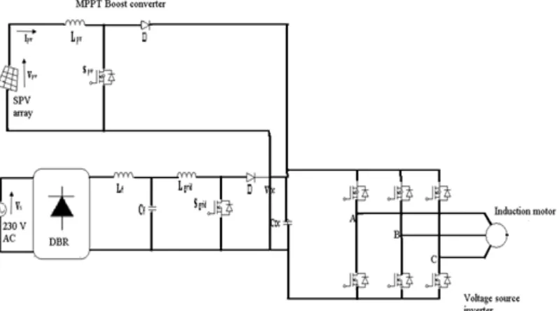
The system configuration for the solar grid interfaced system is shown in the Figure.1. It consist of the Solar PV array, two boost converter one is the MPPT boost converter and the other one is boost converter on the grid side, voltage source inverter and a diode bridge rectifier. The AC voltage to the induction motor is given by the voltage source inverter (VSI). To step up the voltage on the grid side, boost converter is used. The output of the diode bridge rectifier is connected to the L-C filter to eradicate the ripple [13].
1 Department of Electrical and Electronics Engineering, Pondicherry Engineering College, Puducherry, India 2 Department of Electrical and Electronics Engineering, Pondicherry Engineering College, Puducherry, India
Figure 1. Grid connected Solar interfaced system
2.2 Design of the solar grid interfaced system
Design of solar PV array
The solar panel chosen is LG Electronics LG220R1W-G2, the maximum power obtained from this panel is 220W. There are 2 parallel string connected to increase the maximum current and 11 series connection to increase voltage. The maximum power obtained from the solar panel is 4.4KW.The power rating of the three phase induction motor is 4 KW.
)
(
)
Im
(
Np
p
X
Ns
Vmp
Pmp
(1)= 4.4 KW
Where Vmp is the maximum voltage of a module, Imp is the maximum current of a module, Pmp is the maximum power of the
array.
The calculation for the DC link capacitor is shown below
DC
C
=]
[
6
1 2 2 DC DC LLV
V
It
V
(2)Where VDC is the DC bus voltage and VDC1 is the reference bus DC voltage.
For the boost converter the duty ratio is calculated by using (3), the inductor on the PV side is calculated is calculated by using (4), the inductor on the grid side is calculated by using (5)
PV
D
= DC MP DCV
V
V
(3) s mp PVf
I
D
V
L
1
(4)L sw a a DC grid
I
f
D
D
V
L
(
1
)
(5)Where VMP is the maximum power voltage, fs is the switching frequency ,IL is the inductor current , D is the duty ratio on the
PV side , Da is the duty ratio on the grid side.
2.3 Control scheme for the system
The solar grid interfaced system consists of the two power source. The power from the solar PV array is given priority than the grid connected system. In order to extract the maximum power from the solar PV array an incremental conductance (IC) algorithm is used.
Figure 2. Control scheme for the System
3. MODE OF OPERATION
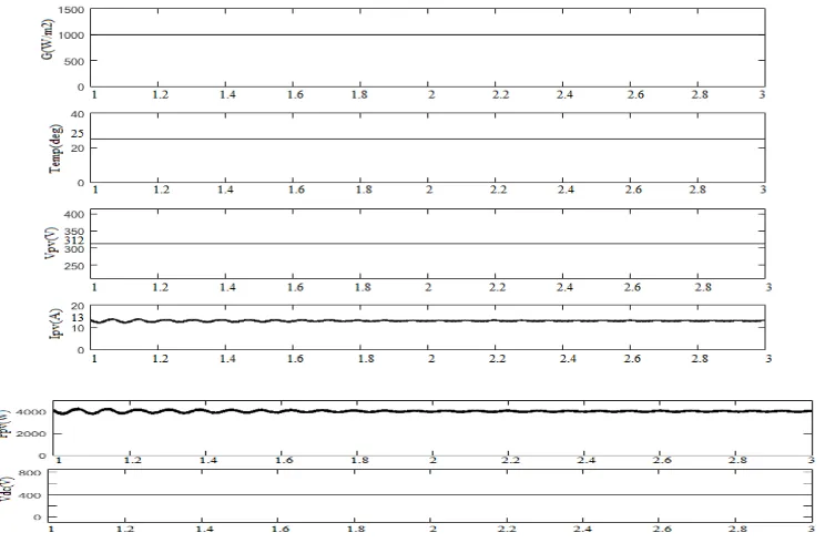
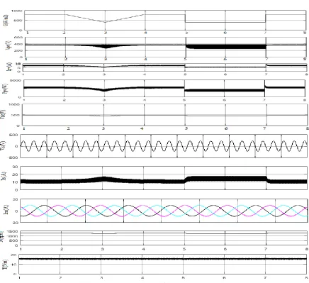
The mode I is called as the standalone operation, this mode is operated in the presence of the solar power. The PV side voltage is increased to the reference voltage by using the boost converter and the PV operating point is maintained at the maximum power point. The output from the boost converter is fed to the voltage source inverter which runs the motor at the rated speed. The simulation result of the Mode I is shown in the figure.6.
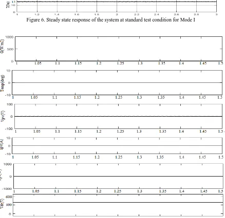
The mode II operates when there is no sufficient irradiance and during that period the system draws power from the AC mains. Grid supply is connected to the diode bridge rectifier, which is followed by the boost converter, capacitor, voltage source inverter and the induction motor. The simulated result of the Mode II is shown in the figure.7.
The mode III will operate when there is power available from both the solar photovoltaic array and grid. In this mode more priority will be given to the PV source and the remaining power has been taken from the grid. The consumption of power from the grid is less and thus we will be able to reduce our electricity bill. The performance of the system is done under the dynamic conditions. The simulated result of the Mode III is shown in the figure.8.
3.1 Maximum power point tracking algorithm
Perturb and Observe (P&O)
In the Perturb and Observe algorithm perturbation is introduced. The power of the solar module will change continuously because of the perturbation. The perturbation will be continued if the power increases. After the peak power is reached the power will decrease. When the steady state is reached it will start to oscillate at the peak point. In order to keep the power variation small the perturbation size will also kept small. The detailed explanation of P and O is explained in the flowchart fig.4.
Incremental Conductance Algorithm
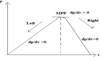
The terminal voltage of the PV array is adjusted in accordance to the maximum power point voltage in the incremental conductance. And it will be based upon the incremental and instantaneous conductance of the photovoltaic Module. The PV curve for incremental conductance is shown below. The flowchart for incremental conductance is shown in the fig.5.
Figure 5. Flowchart for Incremental Conductance Algorithm .
4.SIMULATED RESULT
Figure 7.Steady state response of the system in Mode II
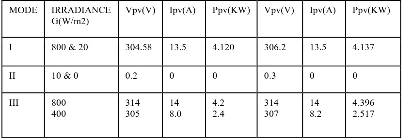
400 305 8.0 2.4 307 8.2 2.517
Table 1 show the comparison between the Perturb and observe and the incremental conductance, the maximum power obtained from the incremental conductance is higher than the Perturb and Observe.
5. CONCLUSION
The solar grid interfaced system has been designed, modelled and simulated in MATLAB. The simulation performance of the system in steady state and with varying irradiance has been performed. The maximum power from the Solar PV array has been extracted by using the Perturb and Observe method and incremental conductance. The control scheme has been designed and is made to operate in three different modes standalone, grid tied system and the hybrid mode of operation. So the burden on the grid gets reduced and the electricity bill will get reduced. In this the incremental conductance is able to track more efficiently than the Perturb and Observe. The power obtained from the incremental conductance is slightly higher than that of perturb and observe.
6. APPENDIX
6.1 .Photovoltaic Array Parameters
Open circuit voltage (Voc) = 36 ; Short circuit current( Isc) = 8.06 ;Module in series=11;Module in parallel= 2; Maximum power point voltage = 315.7V ; Maximum power point current= 15.38A ;Power at maximum power point = 4.4KW.
B. Parameters of Induction Motor
4KW, 230 V, 50 Hz Three phase, 1430 rpm, 4 pole, Rs =1.405Ω , Rr =1.395Ω, Xs =1.007Ω, Xr = 0.9212Ω, Xm =23.56Ω .
7. REFERENCES
[1] Smil, V.: „Power density: a key to understanding energy sources and uses‟ (MIT Press, 2015).
[2] Rajan Kumar and Bhim Singh, “Buck Boost converter fed BLDC motor drive for solar PV array based water pumping,” IEEE International Conference on Power Electronics, Drives and Energy Systems (PEDES), 16-19 Dec. 2014, pp.1-6.
[3] Cui, W., Luo, H., Gu, Y., et al.: „Hybrid-bridge transformerless photovoltaic grid-connected inverter‟, IET Power Electron., 2015, 8, (3), pp. 439–446. [4] Slabbert, C., Malengret, M.: „Grid connected/solar water pump for rural areas‟. IEEE Int. Symp. on Industrial Electronics, 1998. Proc. ISIE, 1998, vol.
1, pp. 31–34.
[5] M.A.G. de Brito, L. Galotto, L.P. Sampaio, G. de Azevedo e Melo and C.A. Canesin, “Evaluation of the Main MPPT Techniques for Photovoltaic Applications,” IEEE Trans. Ind. Electron., vol.60, no.3, pp.1156-1167, March 2013.
[6] B. Subudhi and R. Pradhan, “A Comparative Study on Maximum Power Point Tracking Techniques for Photovoltaic Power Systems,” IEEE Trans. Sustain. Energy, vol. 4, no. 1, pp. 89-98, Jan. 2013.
[7] J.D. Bastidas-odriguez, E. Franco, G. Petrone, C. Andrés Ramos-Paja and G. Spagnuolo, “Maximum power point tracking architectures for photovoltaic systems in mismatching conditions: a review,” IET Power Electronics, vol.7, no.6, pp.1396-1413, June 2014.
[8] Elgendy, M.A., Atkinson, D.J., Zahawi, B.: „Experimental investigation of the incremental conductance maximum power point tracking algorithm at high perturbation rates‟, IET Renew. Power Gener., 2016, 10, (2), pp. 133–139
[9] Kok Soon Tey and S. Mekhilef, “Modified Incremental Conductance Algorithm for Photovoltaic System under Partial Shading Conditions and Load Variation,” IEEE Trans. Ind. Electron., vol.61, no.10, pp.5384*A=D:, Oct. 2014.
[10] Sera, D., Mathe, L., Kerekes, T., et al.: „On the perturb-and-observe and incremental conductance MPPT methods for PV systems‟, IEEE J. Photovolt., 2013, 3, (3), pp. 1070–1078.
[11] G.-C. Hsieh, C.-Y. Tsai, and H.-I. Hsieh, “Photovoltaic power-increment aided incremental-conductance maximum power point tracking using variable frequency and duty controls,” in Proc. 3rd IEEE Int. Symp. Power Electron. Distrib. Gener. Syst., Aalborg, Denmark, Jun. 2012, pp. 542–549. [12] M. A. Elgendy, B. Zahawi, and D. J. Atkinson, "Assessment of perturb and observe MPPT algorithm implementation techniques for PV pumping
applications," IEEE Trans. Sustain. Energy, vol. 3, no. 1, pp. 21-33, Jan. 2012.
[13] Vlatkovic, V., Borojevic, D., Lee, F.C.: „Input filter design for power factor correction circuits‟, IEEE Trans. Power Electron., 1996, 11, (1), pp. 199– 205