JETIR1504090 Journal of Emerging Technologies and Innovative Research (JETIR) www.jetir.org 1339
Performance Analysis on the Influence of Air Strike
Angle to Vertical Axis Wind Turbine
1
Tushar Gundarneeya,2Mayank Patel
1
Assistant Professor Mechanical Engg.,2Lecturer Mechanical Engg. 1
Mechanical Engg. Deptt 1
Government Engg. College, Dahod, Gujarat, India
Abstract—The small wind turbine industry has recently seen a significant amount of growth due to the need for energy
storage and a reduced dependence on fossil fuels in rural environments. A novel vertical axis wind turbine (VAWT) has been developed that consists of several vertically-stacked segments. Computational fluid dynamics (CFD) simulations were performed in the present study using ANSYS CFX, a commercially-available CFD package, to characterize the behavior of the new VAWT. Static three-dimensional CFD simulations were conducted. The static torque characteristics of the turbine and the simplicity of design highlight its suitability for the small wind turbine market. The major factor for generating the power through the VAWT is the velocity of air and the position of the blade angle in the VAWT blade assembly. The study presents the effect of the position of the blade angle from 0 degree to the 30 degree on the power developed by the VAWT. Literature revealed that some parameter like wind speed, tip-speed ratio, air-strike angle, solidity, surface roughness, pitch angle has significant sensitivity for the efficiency change to the performance of the vertical axis wind turbine. So the parameter like wind speed, tip-speed ratio, air strike angle are likely to use in the research for these dissertation work. CFD workbench of ANSYS is used to carry out the virtue simulation and testing. The software generated test results are validated through the experimental readings. Through this obtainable result will be in the means of maximum constant power generation from VAWT.
Index Terms—Vertical axis wind turbine, Aerodynamic, ANSYS CFX software, Ansys
_________________________________________________________________________________________________
I.INTRODUCTION
The focus on Renewable Energy Resources has increased significantly in the recent years in the wake of growing environmental pollution, rising energy demand and depleting fossil fuel resources. Different sources of renewable energy include biomass, solar, geothermal, hydroelectric, and wind. Among these resources wind has proved to be a cheaper alternative energy resource and hence extensive research efforts have been put to improve the technology of electricity generation through wind. The world has enormous potential of wind energy that can be utilized for electricity generation. Currently, large scale VAWTs are not economically attractive; however, they offer energy solutions for remote places away from the main distribution lines and places where large wind farms cannot be installed due to environmental concerns and small scale dispersed generation units are preferred. That is why mass production of VAWTs has recently been started as small scale wind power generating units
II.CONFIGURATIONS
A great degree of design versatility exists in the vertical axis wind turbines as shown in Table. There are a few problems inherent to the currently available designs including low starting torque, blade lift forces, low efficiency, poor building integration, etc. In the past few decades, the engineers came up with many new and innovative design approaches to resolve these issues associated with VAWTs. A detailed review of VAWT configurations available till now and the work done on each configuration has been discussed in the following sections. Darrieus wind turbine designs were first patented in 1931. These types of turbines have highest values of efficiency among VAWTs but generally suffer from problems of low starting torque and poor building integration. Darrieus type wind turbines have many variants, as discussed in the following lines, all of which are Lift-type wind turbines, i.e. lift forces acting on the blades of turbine cause the rotor to rotate and hence generate electricity.
III. LITERATURE SURVEY
JETIR1504090 Journal of Emerging Technologies and Innovative Research (JETIR) www.jetir.org 1340 overcome these losses.The straight turbine rotor blade, with an aspect ratio of 4:1, operates at relatively low tip speeds and its performance shows a clear dependence on the rotor blade surface finish. Below a critical Reynolds number (30,000), the performance is enhanced by having the surface of the turbine roughened, but above this Reynolds number the power coefficient is degraded. Balduzzi, Alessandro Bianchini, Ennio Antonio Carnevale[2]: The tests also shows that the two and three bladed rotor models produces similar peaks in performance coefficient, but that the three bladed design did so at a much reduced TSR.Computational predictions of the performance coefficient of this turbine were carried out and the 3D simulations were shown to be in reasonably good agreement with the experimental measurements, considering errors and uncertainties in both the CFD simulations and the wind tunnel measurements. The 2D simulations showed a significantly increased performance compared to the 3D simulations and this was shown to be mainly due to the presence of the large tip vortices present in the real turbine and the 3D simulations. Simulations illustrated the periodic pulsing nature of the tip vortices caused by the changing lift generated by the rotor blades as they travel through each rotor revolution. M. EI-Samanoudy , A.A.E. Ghorab, Sh.Z. Youssef [3]At phases where higher amounts of lift are generated, stronger tip vortices are present, whereas at phases where little lift is generated, the vortices are significantly reduced.An assessment of the performance of a novel vertical axis wind turbine was conducted using RANS CFD simulations. Steady and rotating validation studies were conducted using experimental data for a Savonius rotor. The static and dynamic torque curves for the Savonius rotor were well characterised. Steady two-dimensional CFD simulations were conducted and it was determined that the Aeolun Harvester_ produces a comparable amount of static torque to existing Savonius rotors. Rotating three-dimensional CFD simulations demonstrated that the average dynamic torque generated by this new rotor decays more rapidly with increasing tip speed ratio than the torque output of existing Savonius rotors. K. Pope, V. Rodrigues, R.Doyle,[4]Pressure coefficient contours and the local torque coefficient indicate that this rapid decay in torque with increasing tip speed ratio occurs due to stagnation effects acting on the convex side of the outer wall as the blade is retreating. These stagnation effects increase with increasing tip speed ratio and have similar characteristics to the torque production mechanisms observed on Savonius rotors. The verification, validation, and prediction presented in this work demonstrated the applicability of RANS in the development of vertical axis wind turbines. The results of the study, however, have shown that the shape of the inner and outer rotor walls should be the focus of future work as a means to increase the torque generated by the rotor to render it more competitive with existing designs. Robert Howell, Ning Qin, Jonathan Edwards, Naveed Durrani, [5]A numerical model (based on the application to CFD of the aerodynamic principles which are currently applied to BE-M theory for rotor performance prediction) for the evaluation of energy performance and aerodynamic forces acting on a straight bladed vertical-axis Darrieus wind turbine has been presented.A simplified aerodynamic model (based on the analysis of kinematic and dynamic quantities at discrete and fixed rotor azimuthal positions along blades trajectory) was also presented, allowing the correlation between flow geometric characteristics.
IV. CFD ANALYSIS OF VERTICAL AXIS WIND TURBINE BLADE.
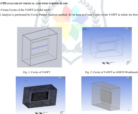
First Create Cavity of the VAWT in Solid works
CFX Analysis is performed by Cavity Pattern Analysis method. So we have to Create Cavity of the VAWT in which Air flows
Fig. 1: Cavity of VAWT Fig. 2: Cavity of VAWT in ANSYS Workbench
JETIR1504090 Journal of Emerging Technologies and Innovative Research (JETIR) www.jetir.org 1341 Import IGES File in the ANSYS Workbench environment for meshing.
Before meshing we have to Verify Geometry for Clean-up Create Volume Mesh.
Element
Import Mesh File into ANSYS CFX Pre
In general, a finite-element solution may be broken into the following three stages. (1) Pre-processing: defining the problem
The major steps in pre-processing are (i) define key points/lines/areas/volumes,(ii) define element type and material/geometric properties, and (iii) mesh lines/areas/ volumes as required.
(2) Solution: assigning loads, constraints, and solving Here, it is necessary to specify the loads (point or pressure), constraints (translational and rotational), and finally solve the resulting set of equations.
(3) Post processing: further processing and viewing of the results
In this stage one may wish to see (i) lists of nodal displacements, (ii) element forces and moments, (iii) deflection plots, and (iv) Pressure contour diagrams or temperature maps.
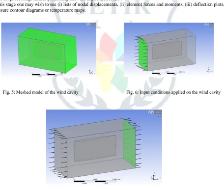
Fig. 5: Meshed model of the wind cavity Fig. 6: Input conditions applied on the wind cavity
Fig. 7: Input and Output condition of the wind cavity Define Inlet and Outlet Condition as Below. Go on Solver Option. Set Iteration to 1000 Run Analysis.
ANSYS CFX will Create Supersonic Nozzle.res file. Open CFX Post.
JETIR1504090 Journal of Emerging Technologies and Innovative Research (JETIR) www.jetir.org 1342
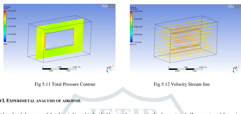
V.RESULTS
Fig 5.11 Total Pressure Contour Fig 5.12 Velocity Stream line
VI.EXPERIMETAL ANALYSIS OF AIROFOIL
It has already been proved that the wind tunnel is the ideal location for systematic development work. However, tunnel dimensions for Wind Turbine Blades are problematic. Precise aerodynamic measurements can just about be made on full-size small blades in the largest wind tunnels available today. Larger blades create too larger an obstructions in the test section, both lengthwise and crosswise .they must therefore be studied in reduced scale.The prerequisite for this is similarity in geometry and flow dynamics that is precise and detailed replicas of the originals and identical Reynolds numbers for models and full-size version.Study of the flow over blade geometries can be performed by experiments in wind tunnels, as well as by numerical simulation. Wind tunnels have been extensively used for years in wind turbine aerodynamics in order to improve modern wind turbine design. In the past, experiments mainly involved the measurement of the aerodynamic coefficients and flow visualization over wind turbine blade. Performance on wind-tunnel experiments to measure the wakes of wind turbine blade are already been done. Also the experiment on performance of windtunnel tests using 1/5scale basic wind turbine structures.There are various types of Wind Tunnels: -Blower tunnel,Suction tunnel,Open jet tunnel,Induction tunnel,Supersonic tunnel.But for this work, slow speed suction wind tunnel is used to check the various effects of control parameters on the response parameters relative to the various aerodynamic bodies taken into this experimentation. Air is sucked in the tunnel through the contraction, honeycomb, test section, etc. by an exhaust fan. The air jet in the entire tunnel is slightly below atmospheric pressure; therefore for a given velocity in the test section the power required to drive the fan is comparatively less. Below figure shows the Slow speed Suction type Wind Tunnel.
Fig. 5.1: Wind tunnel
The specifications of various components are as follows:
Blower: The specifications of blower are as follows: kW/HP-4/5,Speed-3000,Volts-220,Amp-20
(1) Nozzle:The contraction or the nozzle feeds the test section with a jet of uniform velocity. The modal to be tested if fixed here with suitable supports. A transparent window of a strong glass is often provided on one or both the side walls on the test section. This facilitates in handling the modal and the instrument and also permits the optical measurement in the flow over the model surfaces.The function of nozzle is as below: Accelerates the flow, Makes the velocity distribution over the cross section of the flow more uniform,Reduces the intensity of the turbulence in the air stream,Serves to measure the wind speed in the test section.
JETIR1504090 Journal of Emerging Technologies and Innovative Research (JETIR) www.jetir.org 1343 surfaces.
(3) Power unit: This is the unit which consist of voltage control devices which supply the proper amount of voltage to the blower motor.
(4) Diffuser: The diffuser collects the flow from the test section and raises the pressure on the air for discharging it into the atmosphere or the return circuit in case of a close circuit tunnel. Boundary layer thickening and separation on account of the strong pressure gradients in the diffuser should be minimized. The diffuser throat is often made flexible, this allows the throat to be varied for starting and running conditions. After starting the diffuser throat area is reduced for optimum running conditions.
(5) Pressure measuring unit: This unit measures the pressure differences of the model. Through this unit the drag coefficient can be calculated by using pressure difference.
(6) Honey comb: The flow from the compressor/blower or fan is settled in a large chamber called the settling chamber, this is provided with wire gauges and arrays of honeycombs to straighten the flow and remove irregularities in it.
IV.CONCLUSIONS
CFD is capable of designing the VAWT with higher degree of accuracy. It can also be used for the optimization of blade design. Moreover, flow field around various configurations’ blades can also be visualized with the help of CFD. It has not only accel erated the design process of VAWT but also has brought down the overall cost of designing.Various vertical axis wind turbines can offer solution to the energy requirements ranging from 2 kW to 4 MW with a reasonable payback period. Coefficient of power can be maximized by selecting a suitable TSR range for various configurations. The parameter like air strike angle and aerofoil of the blade, wind speed, tip speed ratio, chord length are one of most effecting parameter for thevertical axis wind turbine. By the analysis using this parameter can become useful in the performance optimization of the vertical axis wind turbine.
REFERENCES
[1] Marco Raciti Castelli, Alessandro Englaro, Ernesto Benini, “The Darrieus wind turbine: Proposal for a new performance prediction model based on CFD”, Science Direct, 20 May 2011.
[2] Francesco Balduzzi, Alessandro Bianchini, Ennio Antonio Carnevale, Lorenzo Ferrari, Sandro Magnani “Feasibility analysis of darrieus vertical-axis wind turbine installation” Science Direct, 8 December 2011.
[3] M. EI-Samanoudy , A.A.E. Ghorab, Sh.Z. Youssef, “effect of some Design parameters on the performance of giromill vertical axis wind turbine” Science Direct, 5 August 2010.
[4] A K. Pope, V. Rodrigues, R.Doyle,. Tsopelas, R. Gravelsins, G.F. Naterer, E.Tsang, “effect of Stator vanes on power coefficient of a zephyr vertical axis wind turbine”,Science Direct, 11 October 2009.
[5] Robert Howell, Ning Qin, Jonathan Edwards, Naveed Durrani, “wind tunnel Numerical study of a small vertical axis and wind turbine”, Science Direct, 20 July 2009.
[6] Ivan Dobrev, FawazMassouh, “CFD and PIV investigation of Unsteady flow through Savonius wind turbine”,energy, May 2011.
[7] Shwan Armstrong, Andrzej Fiedler, Stephen Tullis “Flow separation on a high Reynolds number, high solidity vertical axis wind turbine with Straight, canted blades, Canted blades with fences” , Renewable energy, 3 September 2011.
[8] Nasir Hayat, Ahmad UzairFarooq, Zain Ali, Sh. RehanJamil, ZahidHussain, “Vertical axis wind turbine - A review of various configuration and design techniques”, Renewable energy, 18 December 2011.
[9] S. McTavish, D. Feszty, T. Sankar, “Study and rotating computational fluid dynamics simulation of a novel vertical axis wind turbine for small-scale power generation” energy, 13 October 2011.
[10] Marco RacitiCastelli, Alessandro Englaro, Ernesto Benini, “The Darrieus wind turbine: Proposal for a new performance prediction model based on CFD”, energy, 20 May 2011.
[11] Francesco Balduzzi, Alessandro Bianchini, Ennio Antonio Carnevale, Lorenzo Ferrari, SandroMagnani “Feasibility analysis of darrieus vertical-axis wind turbine installation Renewable energy, 8 December 2011.
[12] M. EI-Samanoudy , A.A.E. Ghorab, Sh.Z. Youssef, “effect of some Design parameters on the performance of giromill vertical axis wind turbine” Renewable energy, 5 August 2010.
[13] K. Pope, V. Rodrigues, R.Doyle, A. Tsopelas, R. Gravelsins, G.F. Naterer, E.Tsang, “effect of Stator vanes on power coefficient of a zephyr vertical axis wind turbine”, energy, 11 October 2009.
[14] Robert Howell, Ning Qin, Jonathan Edwards, Naveed Durrani, “wind tunnel Numerical study of a small vertical axis and wind turbine”, Renewable energy, 20 July 2009.
[15] ChalothronThumthae, TawitChitsomboon, “Optimal angle of attack for untwisted blade wind turbine”, Renewable energy, 28 September 2008. [16] P.Deglaire, S.Engblom, O. Agren, H. Bernhoff, “analytical solution for a Single blade in vertical axis turbine motion in two-dimention” Energy, 25
November 2008.
[17] “Wind Turbine Design: With Emphasis on Darrieus Concept”, author-Ion Paraschivoiu, Presses inter [18] “Innovation in Wind Turbine Design”, Peter Jamieso, Wiley, 05-Jul-2011 - Technology & Engineering. [19] “Wind Turbine Technology”, A. R. Jha, Ph.D. CRC Press, 03-Jun-2011 - Technology & Engineering.
[20] Akiyoshi Iida,Akisato Mizuno,Keiko Fukudome“Numerical Simulation of Aerodynamic Noise Radiated form Vertical Axis wind Turbines”. Renewable Energy. Jun 2004.
[21] Zhang Guoyu, FengWeimin, Liu Changlu, Yu Jianfeng. “Simulation study on Blade Design and Aerodynamic Function ofWind Turbine” , Energy research &utilization. 2009
[22] L.G. Nikolaou,E SPolitis,P KChaviaropoulos,“Modeling the flow around airfoils equipped with vortexgenerators using a modified 2D Navier – Stokes solver”. Journal of Solar Energy Engineering,2005.
[23] Zhao weiguo,Lirennian,Li de shun,Yangcongxin,zhangyuliang. “Choice of Turbulence Model for Numerical Simulationof Special Airfoil of Wind Turbine” Natural science edition,2007
[24] Huang Jian-feng , Zhang Li-xiang, He Shi-hua. “Numerical Simulation of 3-D Steady and Unsteady Flows in Whole FlowPassage of a Francis Hydro-turbine”.sustainable energy technology, 2007
Experiment
Air inlet Angle Inlet Velocity
m/s
Exit Velocity m/s