GLOBAL JOURNAL OF ADVANCED ENGINEERING TECHNOLOGIES AND
SCIENCES
STUDY THE EJECTOR’S PERFORMANCE CHANGING WITH IT’S GEOMETRIC
PARAMETERS
Wang Pu*,Wang Heshun, Zhu Weibing
*
School of Mechanical Engineering and Automation, Xihua University, Chengdu, Sichuan Province,
610039, China
ABSTRACT
Hydrokinetics software FLUENT is adopted to perform numerical simulations on the ejector flow field, the entrainment ratio of ejector is analyzed by changing the diameter of the primary nozzle and the constant area mixing chamber .The result shows that the primary nozzle and constant area mixing chamber have great influence on the performance of ejector, and existing optimal throat diameter of primary nozzle and diameter of constant area mixing chamber make the entrainment ratio reach maximum, it has great significance to guidance the design of ejector.
KEYWORDS: Ejector, Fluent, Numerical simulation, Flow field.
INTRODUCTION
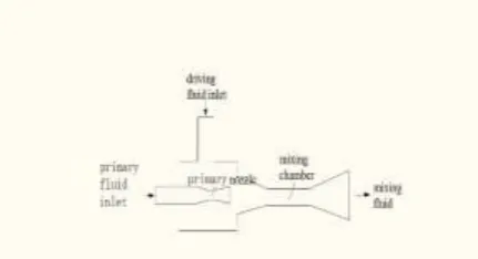
Ejector is a widely used fluid machine. It uses a primary fluid jet to achieve energy conversion, it is widely used in water conservancy, electricity, transportation, chemical industry, metallurgy , petroleum, mining, nuclear industry, aviation and aerospace and other fields because its simple structure, low cost, reliable, easy installation and maintenance, sealing, and can take advantage of low-grade heat source drive, etc. Ejector has been invented for a long time, the structure of ejector based on the classical theory almost is fixed. However, the actual operation of the ejector operating parameters are not immutable, the performance of ejector changes over the ejector’s operating conditions to the fixed structure of ejector. Therefore, the study of its mechanism have get more attention from many scholars. The primary about the ejector’s research mainly reflected in two aspects.First, analysis the influence of the primary parameters and the structure of the ejector to its performance, the main method is experimental or numerical analysis based on one-dimensional isentropic assumption. The other hand is to capture the complex flow inside the ejector, analysis the performance of ejector from its mechanism.Till now, this research is very lack. With the development of the experimental test conditions and CFD simulation methods, the analysis about the ejector will be more in-depth. Figure 1 is the structure schematic of ejector .As used herein, FLUENT software, internal injector flow field numerical simulation, analysis variation of pressure, speed and other parameters are used to analyze the performance of the ejector.
Figure 1. the structure schematic of ejector
CALCULATION METHOD DESCRIPTION
Control equationAccording to the characteristics of the flow field inside the ejector, still used thermodynamic mode, make the following assumptions:
1) The fluid in the ejector is one-dimensional steady-state flow;
2) The primary fluid and driving fluiddo not mix at the exit of the nozzle;
3) The primary fluid and driving fluid are saturated at the entrance of the ejector; Ignore the kinetic energy at the entrance and exit of ejector;
4) The nozzle and diffuser section are isentropic process, do not consider heat loss; 5) Ignore the impact of fluid buoyancy.
HdV
dA
G
F
WdV
t In Eq:
Ω : Control volume;
∂Ω : The boundary of the control volume; W : The variables to be solved;
F : inviscid fluxes; G : Viscous flux; H : Energy option.
Meshing
Considering the speed of driving fluid mixing is very small compared with the primary fluid at the entrance of the ejector’s mixing chamber ,to simplify the calculations, ignore the disturbance of driving chamber by lateral fluid into the ejector, so the flow process in the ejector can simplified to two-dimensional flow. Compared with the computations, there are no significant difference in the simplified two-dimensional model and three-dimensional models, Therefore, this text uses a two-dimensional model to simulate.
The flow process inside the ejector involves gas supersonic flow, shock waves and mixing process, so we solve the mass of water vapor, momentum and energy conservation equations for this calculation. Turbulence model using the standard Κ-ε model. The flow field affected by the presence of turbulent flow cannot be ignored because the exit of wall, so the sticky wall function are used to contact affected areas between the wall and the fully turbulent layer. The population of the primary fluid and driving fluid are using the pressure boundary conditions in pressure inlet and pressure outlet.
Simulation results
The initial setup parameters are as follows: Primary fluid
driving fluid Mixed fluid
The main structural dimensions of ejector are as follows: The cross sectional diameter of the primary fluid inlet:12 (mm); The cross sectional diameter of the driving fluid inlet: (12) mm; The cross sectional diameter of the mixing chamber:(40)mm; The tapering length of primary nozzle :(25)mm;
The cross sectional diameter of primary nozzle’s inlet :(15)mm; The throat length of primary nozzle :(30)mm;
The throat diameter of primary nozzle :(6)mm;
The diverging section length of primary nozzle :(45)mm;
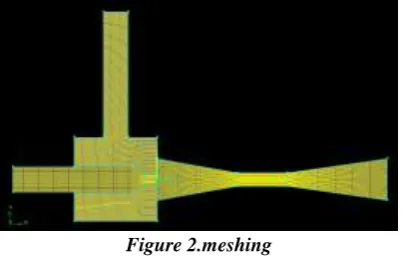
The cross sectional diameter of the work nozzle‘s outlet: (20)mm. Figure 2 shows the schematic view of meshing.
Figure 2.meshing
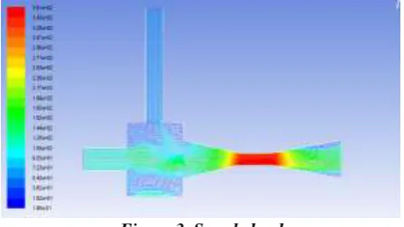
Figure 3. Speed cloud
As can be seen from Figure 4, the distribution of pressure in the ejector consistent with the fluid velocity, and it produces shock at the vicinity of the nozzle’s outlet and the diffuser chamber’s inlet , which make the velocity and pressure mutation.
Figure 4. Pressure field cloud
ANALYSIS RESULTS
The influence of mixing chamber diameter
The diameter of the mixing chamber is an important factor which can affect the performance of the ejector, it is one of the most important parameters when we analyze the structure of the ejector. While keeping other parameters do not change, we make a simulation study only made the mixing chamber diameter varies from 12mm to 20mm to get the performance of ejector.
From Figure 5, while the mixing chamber diameter is 16mm,the entrainment ratio is highest,mean the best ejector performance. In this condition, while the mixing chamber diameter is less than 16mm, the entrainment ratio increased with the mixing chamber diameter increasing, while the mixing chamber diameter is more than 16mm, the entrainment ratio slowly decreased increased with the mixing chamber diameter increasing; while the mixing chamber diameter is less than 12mm, the entrainment ratio will be a sharp decreases, cause the ejector does not work, we must keep the mixing chamber diameter more than 12mm. In order to keep the best entrainment ratio, we should make the mixing chamber diameter 16mm.
The influence of primary nozzle throat diameter
While keeping other parameters do not change, we make a simulation study only made the primary nozzle throat diameter varies from 6mm to 10mm to get the performance of ejector.
From Figure 6, while the primary nozzle throat diameter is 8mm, the entrainment ratio is highest which is the best ejector performance. In this condition, while the primary nozzle throat diameter is less than 8mm, the entrainment ratio increased with the primary nozzle throat diameter increasing, while the primary nozzle throat diameter is more than 8mm, the entrainment ratio decreased with the primary nozzle throat diameter increasing, while the primary nozzle throat diameter is 8mm, the entrainment ratio is highest.
Figure 6. Entrainment ratio changing with diameter of primary nozzle throat
From Figure 7,we know the contact between steam flow and the primary nozzle throat diameter. while the primary nozzle throat diameter is less than 6mm, steam flow decreases rapidly to zero, the ejector does not work; while the primary nozzle throat diameter changes from 6mm to 8mm, steam flow increased with the primary nozzle throat diameter increasing, while the primary nozzle throat diameter is more than 8mm, the steam flow decreased with the primary nozzle throat diameter increasing, while the primary nozzle throat diameter is 8mm, the ejector steam flow is highest, the entrainment ratio also reaches a maximum.
Figure 7. Steam flow changing with primary nozzle throat diameter
CONCLUSION
This text apply CFD method to study the performance of ejector with it’s geometric parameters. Analyze the influence of mixing chamber diameter and primary nozzle throat diameter to the ejector. The results show that:
1) The mixing chamber diameter has direct influence to the highest entrainment ratio. the entrainment ratio firstly increases and then decreases with the mixing chamber diameter increasing.
This text analyzes the impact of primary nozzle throat diameter and the mixing chamber diameter to the ejector’s performance, inferred the best value range of each parameter, have a certain significance to actual design and operation.
ACKNOWLEDGMENT
This work is support by Xihua University Young Scholars Training Program (No: 01201415), the Open Research Subject of Key Laboratory of Fluid, Machinery and Engineering (No: szjj2015-030), the Projects of “Chun-Hui” Plan (No: Z2014072),the National Natural Science Foundation of China (No: 51005188), and the Natural Science Fund Project of Sichuan Education Department (No: 11ZA285). Many interesting and useful discussions of MPS with colleagues at Xihua University are gratefully acknowledged.
REFERENCES
[1] ZHANG Bo, SHEN Sheng-qiang, LI Hai-jun, Study of a two-dimenSional flow model on design and analysis of ejector key structure[J]. Journal of Dalian University of Technology, 2004,44(3):388-391. [2] SHEN Shengqiang, ZHANG Kun, LIU Jia, YANG Yong, Experimental invtestigation on
performance of adjustable ejector[J]. Journal of Chemical Industry And Engineering (CHINA), 2009,60(6):1398-1401.
[3] XING Guiju, LI Wenzhong, The effective method of increasing of ejector efficiency used in metallurgical industry[J]. Acta Metallurgica Sinica 2000,36(4):445-448.
[4] ZHANG Kun,LIU Jia,SHEN sheng-qiang, Numerical simulation of flow inside an adjustable ejector[J]. Journal of Dalian University of Technology, 2010,50(6):942-945
[5] Guo Jian, Shen Henggen,Liang Zhen, Sun Mingming, Improvement on ejector design and CFD modeling[J],Cryogenics&Superconductivity,2009,37(1):63-66.
[6] LlHai-jun ,SHEN Sheng-qiang, Analysis of ejector performance using dimensionless parameters[J]. Journal of Dalian University of Technology, 2007,47(1):26-29.
[7] SHEN Zhi-yong CAO Jia-cong, The Influence of Main Structure to Mini-steam Ejectors' Performance[J]. Building Energy&Environment, 2008, 27(3):29-32.
[8] CHEN Xiu-juan XIAO Li-chun XU Jing-wei, Influence of Structural Parameters Upon Two-Dimensional Flow Field In The Ejector[J]. Thermal Power Generation, 2009, 38(3):40-43,47.
[9] Wang, H.S., Dong, L., Huang, Z.P., Zhang, C.N., et al., Numerical simulation on flow field of aerostati c dry gas seal[J]. Paiguan Jixie Gongcheng Xuebao/Journal of Drainage and Irrigation Machinery Engi neering, 2011. 29(2): p. 165-169.
[10]Wang, H., W. Zhu, Z. Huang, C. Zhang, and J. Zhang, Research on the cone angle and clearance of main pump seal. Journal of Mechanical Science and Technology, 2015. 29(7): p. 2939-2947.
[11]Zhu, W.B., Zhou, S.R., Wang, H.S., Performance of externally pressurized dry gas seal. in 2011 Intern ational Conference on Materials and Products Manufacturing Technology, ICMPMT 2011, October 28, 2011 - October 30, 2011. 2011. Chengdu, China: Trans Tech Publications; p. 610-614.
[12]Xiao, F., Research on the Flow Field of Convergent Cone-type Mechanical Seal [D], Xihua university, 2014.
[13]Zysztof Banasiak,Attain Hafner,Trond Andresen.Experimental and numerical investigation of the influence of the two—phase ejector geometry on the performance of the R744 heat pump[J]. International Journal of Refrigeration,2012,35(6):1617-1625.
[14]Bartosiewicz Y,Aidoun Zine, Desevaux P, Mercadier Yves.Numerical and experimental investigations on supersonic ejectors.[J].Heat Fluid Flow,2005,26:56—70.
[15]Pianthong kseehanam w,behniam,et al.Investigation and improvement of ejector refrigeration system using computational fluid dynamics technique[J].Energy Conversion and Management,2007,48(9)
:2556—2564
[16]Zbolcs Varga,Oliveira Armando c,Sosaan Diaconu.Influence of geometrical factors Oil steam ejector performante—A numerical assessment[J].International Journal of Refrigeration,2009,32(7)