https://dx.doi.org/10.22161/ijaems.4.6.4 ISSN: 2454-1311
Parametric and Quantitative Analysis on the
Development of Shell and Tube Heat Exchanger
Olaiya Kamorudeen Adesina
1, Alabi Ismaila Olanrewaju
2, Okediji Adebunmi
Peter
3, Alonge Oluwasanmi Iyiola
41Department of Mechatronics Engineering, The Polytechnic, Ibadan, Nigeria
Email: [email protected]
2, 3, 4 Department of Mechanical Engineering, Elizade University Ilara-Mokin, Ondo State, Nigeria 2Email: [email protected]; [email protected]
3Email: [email protected] 4Email: [email protected]
Abstract— The importance of mini shell and tube heat
exchangers (STHEs) in industrial and other engineering applications cannot be underestimated. Hence, based on the problems associated with the design of STHEs, a mini STHE was developed for transfer of heat between two fluids without mixing on the laboratory scale using locally available materials and technology based on an optimized LMTD technique. The performance of the heat exchanger was assessed and evaluated to determine the optimum combination of design parameters. Copper was utilized for the tube side fluid due to its higher thermal conductivity and anti-microbial property, while galvanized steel was used for the shell side fluid due to its cost and corrosion resistance. Parametric studies were carried out on STHE design parameters to obtain an optimal design for efficiency and effectiveness after relevant design considerations. Experimental results were validated with quantitative models, and it was discovered that both Dell-Belaware and Engineering Science Data Unit (ESDU) approaches produced the optimal results required for the selection of shell side and tube fluid film coefficients, respectively over other correlations. In conclusion, the values of parameters of interest were also presented after rigorous mathematical calculations at optimal level and probable recommendations were later made.
Keywords— Dell-Belaware, ESDU, LMTD,
Optimization, STHE.
I. INTRODUCTION
Every living thing is equipped in some way or another with devices that tend to enhance or facilitate the flow of heat (Gawande et al., [7]; Ismael and Kumari, [8]) between two or more fluids at different temperatures (Sandeep and Alkesh, [15]) with maximum rate and minimum investment and running cost (Laxnipriya, [12]). These devices are called heat exchangers. They are highly important equipment in any global scenario due to their
wide use on both domestic and industrial scales. Heat exchangers are responsible for the greatest energy demand in power generation, waste heat recovery and power plants, as well as industrial processes in manufacturing, air-conditioning, refrigeration, space applications, petrochemical industries (Sandeep and Alkesh, [15]), food industries (Jaydeep et al., [9]), chemical and petrochemical plants, petroleum refineries, natural gas processing, and sewage treatment (Gawande et al., [7]).
In heat exchangers, there are usually no external heat and work interactions. The essence of heat exchanger is to recover or reject heat, or sterilize, pasteurize, fractionate, distill, concentrate, crystallize, or control a process fluid (Dawit, [6). In a few heat exchangers, the fluids exchanging heat are in direct contact. In most heat exchangers, heat transfer between fluids takes place through a separating wall or into and out of a wall in a transient manner. In many heat exchangers, the fluids are separated by a heat transfer surface, and ideally they do not mix or leak (Ramesh and Shah, [14]); as cited by (Dawit, [6]). Heat exchanger may be classified according to the following main criteria (Sandeep and Alkesh, [15]; Laxnipriya, [12]).
i. Arrangements: parallel, counter and cross-flows. ii. Shell and tube: Recuperators and Regenerators. iii. Transfer process: Direct contact and Indirect
contact.
iv. Geometry of construction: tubes, plates and extended surfaces.
v. Heat transfer mechanisms: single phase and two phase.
https://dx.doi.org/10.22161/ijaems.4.6.4 ISSN: 2454-1311
pressure relative to the environment and high pressure difference between the fluid streams.
Hence, due to their resistant manufacturing features and design flexibility, shell and tube heat exchangers are the most used heat transfer equipment in industrial processes. They are also easy adaptable to operational conditions. In this way, their design is a very important subject in industrial processes. Nevertheless, some difficulties are found, especially in the shell-side design, because of the complex characteristics of heat transfer and pressure drop (Lokhande and Kumar, [13]). In reality, shell and tube heat exchanger is not suitable for use in aircraft and automotive purposes because the size is relatively large and also weighty (Kamaruddin, [11]). In this work, the main focus is to design a mini shell and tube heat exchanger on a laboratory scale for experimental purposes. Those difficulties reported earlier are examined to come up with a better facility that will be operating at minimal cost under optimized conditions.
Thus, this work is aimed at developing a prototype shell and tube heat exchanger using locally available technology and materials via design based on optimal combination of parameters using LMTD technique, fabrication, as well as, performance evaluation of the facility. This work gives a general overview of heat exchanger together with the exposure on the basic principle and analysis of shell and tube heat exchanger using the LMTD software. Also, it enhances the practical knowledge of machine assembling.
II. DESCRIPTION OF SHELL AND TUBE HEAT EXCHANGER (STHE)
According to Alok et al., [2], shell and tube heat exchangers are classified upon the following factors: construction, flow arrangement, number of shells, and contact between the processing streams, compactness and heat transfer mechanism. Jurandir [10] classified heat
exchanger into two. The first being called ‘the recuperative
type’, in which heat are exchanged on either side of a dividing wall by fluids, while the second is ‘the regenerative type’, in which hot and cold fluids are in the
same space which contain a matrix of materials which work alternately as source for heat flow. However, irrespective of the classifications and types of heat exchangers available in the industry, the Shell and Tube Type heat exchanger is probably the most used and
widespread type of the heat exchanger’s classification
(Vindhya et al., [16]).
Shell and tube heat exchanger is built of a bundle of round tubes mounted in a large cylindrical shell with the tube axis parallel to the shell to transfer the heat between the two fluids. They provide relatively large ratio of heat transfer area to volume and weight and they can be easily cleaned. They offer greater flexibility to meet almost any
service requirement they can be designed for high pressure relative to the environment and high pressure difference between the fluid streams (Sandeep, and Alkesh, [15]). Shell and tube type of heat exchanger is said to have originated from the jacketed coil distiller. It is however majorly used in heavy industries as well as in residential hot water heating system (Alfred, [1]), cooling of hydraulic fluids and oil in engines, and other mediums such as swimming pool water or charge air (Asawari, [4]). Perhaps the most common type of heat exchanger in industrial applications is the shell-and-tube heat exchanger, shown in Figure 1. Shell-and-tube heat exchangers contain a large number of tubes (sometimes several hundred) packed in a shell with their axes parallel to that of the shell. Heat transfer takes place as one fluid flows inside the tubes while the other fluid flows outside the tubes through the shell. Baffles are commonly placed in the shell to force the shell-side fluid to flow across the shell to enhance heat transfer and to maintain uniform spacing between the tubes. Despite their widespread use, shell and tube heat exchangers are not suitable for use in automotive and aircraft applications because of their relatively large size and weight. Note that the tubes in a shell-and-tube heat exchanger open to some large flow areas called headers at both ends of the shell, where the tube-side fluid accumulates before entering the tubes and after leaving them.
Shell-and-tube heat exchangers are further classified according to the number of shell and tube passes involved. Heat exchangers in which all the tubes make one U-turn in the shell as shown in figure 2a are called one-shell-pass and two – tube - passes heat exchangers. Likewise, a heat exchanger that involves two passes in the shell and four passes in the tubes as shown in figure 2b is called a two-shell-passes and four-tube-passes heat exchanger (Cengel, [5]).
https://dx.doi.org/10.22161/ijaems.4.6.4 ISSN: 2454-1311
(a) One-shell pass and two-tube passes
(b) Two-shell pass and four-tube passes Fig. 2: Classification of shell and tube heat exchanger
(Cengel, [5])
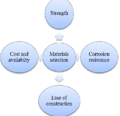
III. METHODOLOGY 3.1 Materials
For the development of a shell and tube heat exchanger, the materials utilized were considered based on the factors in figure 3. Heat exchanger tubes are available in variety of materials, which include both ferrous and non-ferrous materials such as carbon steel, stainless steel, copper, admiralty brass, 90-10 copper-nickel, etc. They are available in a number of wall thickness defined by BWG (Ismael and Kumari, [8]). Galvanized steel was used to construct the shell and the two tube sheets/plates. This was because galvanized steel has high resistant to corrosion. Similarly, the main frame was made up of mild steel because of its strength and rigidity to support load and weight of the machine during operation. The tubes used in this project were made of copper due to its high thermal conductivity and anti-microbial property.
3.2 Method
In the present work, the methodology used in the design of the heat exchanger is studied and presented. The thermal design involves the calculation of shell side and tube side heat transfer coefficients, heat transfer surface area and pressure drops on the shell and tube sides. The mechanical design involves the calculations of thickness of pressure parts of the heat exchanger such as the shell, channel, tube etc. to evaluate the rigidity of part under design pressures. 3.2.1 Description of the project/Working Principle
i. The principle of operation is simple enough, two fluids of different temperatures are brought into close contact but they are not mixing with each other.
ii. One fluid runs through the tube, and another fluid flows over the tube (through the shell) to transfer heat between the two fluids.
iii. The hot water run through the shell while glycerin run through the tube side. In order to transfer heat efficiently, a large heat transfer area were used, so there are many tubes.
iv. The temperatures of the two fluids tend to be equal. The heat is simply exchanged from one fluid to another and vice versa. No energy is added or removed.
Fig. 3: Materials Selection
3.2.2 Component part of a shell and tube heat exchanger The following are the component parts of a shell and tube heat exchanger designed:
1. Tubes: The tubes are the basic component of the shell and tube exchanger, providing the heat transfer surface between one fluid flowing inside the tube and the other fluid flowing across the outside of the tubes. The tubes utilized in this work were welded and made of copper due to its high thermal conductivity. The tubes are 1000 mm and ϕ 12.7 mm each.
https://dx.doi.org/10.22161/ijaems.4.6.4 ISSN: 2454-1311
Fig. 4: Tube Pitch (PT)
3. Tube Sheet/plates: They are used to hold the tubes at the ends. The tube sheet used in the construction is made of circular metal (galvanized steel) plate with holes drilled through for the desired tube pattern, holes for the tie rods, grooves for the gaskets and bolt holes for flanges to the shell.
4. Baffles: It is apparent that higher heat transfer coefficient results when the liquid is maintained in the state of turbulence. To induce turbulence outside the tube it is customary to employ baffles, which cause the liquid to flow through the shell at right angles to the exit of the tubes. Baffles serve two functions: Most importantly, they support the tubes in the proper position during assembly and operation and prevent vibration of the tubes caused by flow-induced eddies, and secondly, they guide the shell-side flow back and forth across the tube field, increasing the velocity and the heat transfer coefficient (Jaydeep et al., [9]). In this project, the baffles machined were made from galvanized steel which is compatible with the shell side fluid. The tube holes must be precise enough to allow easy assembly and field tube replacement, yet minimize the chance of fluid flowing between the tube wall and baffle hole, resulting in reduced thermal performance and increased potential for tube wall cutting from vibration. Baffles do not extend edge to edge, but have a cut that allows shell side fluid to flow to the next baffled chamber. For most liquid applications, the cuts areas represent 20-25% of the shell diameter. In this project cuts areas of 25% was adopted.
5. Nozzles: The entrance and exit ports for the shell
fluid and tube fluid are referred to as “Nozzles”.
These nozzles are pipes of constant cross section welded to the shell and channels. They are used to distribute or collect the fluid uniformly on shell and tube sides.
6. Front-End And Rear End Covers: They are containers for tube fluids for every pass. In many rear end head designs, a provision has been made
to take care of thermal expansion of whole tube bundle. The front-end head is stationery while the rear end head could be either stationary or floating depending upon the thermal stresses between the tubes and shell. But in this project both ends are stationary.
7. Tie Rods and Spacers: Tie rods and spacers are other equivalent means of tying baffle system together. They are provided to retain all transverse baffles and tube support plates securely in position. They serve two purposes; one to maintain the spacing between the baffles and second function is to reduce the fluid by-passing. 8. Shell: The cylindrical shell made of rolled
galvanized steel plate carries flanged connection for water inlet, water outlet, plug and couplings for shell drain and vent. Suitable provisions are made for pressure and temperature measurement. In this project the shell which is cylindrical was produced from the rolling machine.
9. Fluid Chambers: Both the inlet and outlet and rear end fluid chambers are fabricated from rolled galvanized steel plate and are of adequate proportions to minimize pressure drop and turbulence. The inlet and outlet fluid chamber carries water and inspection cover was divided internally into inlet and outlet chambers, each having a flanged connection. The rear end fluid chamber consists of a simple dished cover or a flat end cover. If the water passes are more than two it is divided accordingly.
10. AT-380 AC 220-240V 15W Submersible Water
Pump Aquarium Fountain Pond Pump:
A submersible pump shown in figure 5 has a sealed motor closely coupled to the pump body and pushes water to the surface. It functions via its assembly that is wholly submerged in the fluid to be pumped whereas a centrifugal pump uses a rotating impeller to increase pressure of a fluid.
Fig. 5: Submersible Water Pump
https://dx.doi.org/10.22161/ijaems.4.6.4 ISSN: 2454-1311
pump wash car: "Brandy" brand DC micro-diaphragm pump shown in figure 6 is a self-suction pump with the advantages of chemical pump, using a variety of imported materials synthesis, corrosion resistant, with self-priming function, thermal protection, smooth operation, can long time continuous idling, can long time continuous load operation, small volume, low current, high pressure, low noise, the use of the advantages of long service life, exquisite design, high quality and inexpensive, with oil resistant, heat resistant, acid and alkali resistance, corrosion resistance, chemical resistance properties. Pump body and motor separation, the pump body without mechanical components, no wear. The surface pump used has the following specifications: Rated voltage = 12V DC, Rated power = 45 W, Maximum pressure = 1 MPa, Flow rate = 4 litres/min, Suction diameter 9.2 mm, Discharge diameter = 9.2 mm.
Fig. 6: A Micro-diaphragm pump (self-suction Pump)
3.2.3 Design Consideration
The optimum thermal design of a shell and tube heat exchanger involves the consideration of many interacting design parameters which can be summarized as shown in figure 7.
Fig. 7: Design consideration
Highest thermal performance is the key factor determining the efficiency of any Shell and Tube Heat Exchanger.
Hence, in the design of Heat Exchanger, the foremost considerations should be given to the cost and effectiveness so as to improve its efficiency (Arjun and Gopu, [3]).
3.3 Design Calculations 3.3.1: Assumptions
A selected shell and tube heat exchanger must satisfy the process requirements with the allowable pressure drops until the next scheduled cleaning of plant. The methodology to evaluate thermal parameters is explained with suitable assumptions. The following are the major assumptions made for the pressure drop analysis;
1) The operating or Flow condition is steady and isothermal, and fluid properties are independents of time.
2) Fluid density is dependent on the local temperature only or is treated as constant.
3) The pressure at a point in the fluid is independent of direction.
4) Body force is caused only by gravity.
5) There are no energy sink or sources along streamline; flow stream mechanical energy dissipation is idealized as zero. i.e. Changes from K.E to P.E of fluid streams are negligible
6) The friction factor is considered as constant with passage flow length.
7) The heat exchanger is well insulated so that heat loss is negligible and thus heat transfers from hot to cold fluids are equal.
8) Heat transfer coefficient and fouling factors are constant and uniform
9) Thermal resistance of the inner tube is negligible, since the tube is thin walled and highly conductive.
3.3.2 Modeling Procedures and Design Calculations A. Modeling Procedures
The mathematical model has been constructed considering the principles of heat transfer and fluid mechanics. Shell and tube heat exchangers are designed normally by using
Nusselts, Eissenberg, McNaught, Colbalt, Kern’s,
Taborek, Chemstations, VDI film and Bell-Delaware methods, as well as other correlations like Petukov, Chaddock and Chato adaptation, Duckler (downflow) and Hewitt (upflow) adaptations, and Mikheev correlation etc.
https://dx.doi.org/10.22161/ijaems.4.6.4 ISSN: 2454-1311
Fig. 8: Modeling Procedure
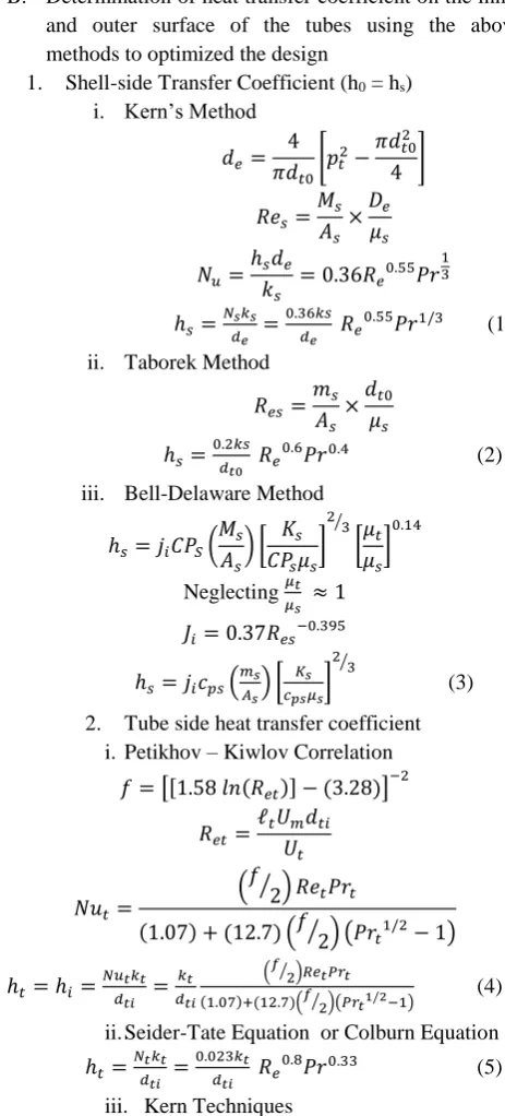
B. Determination of heat transfer coefficient on the inner and outer surface of the tubes using the above methods to optimized the design
1. Shell-side Transfer Coefficient (h0 = hs)
i. Kern’s Method
𝑑𝑒= 4 𝜋𝑑𝑡0
[𝑝𝑡2− 𝜋𝑑𝑡02
4 ] 𝑅𝑒𝑠= 𝑀𝑠 𝐴𝑠 ×𝐷𝑒 𝜇𝑠 𝑁𝑢= ℎ𝑠𝑑𝑒 𝑘𝑠
= 0.36𝑅𝑒0.55𝑃𝑟 1 3 ℎ𝑠= 𝑁𝑠𝑘𝑠 𝑑𝑒 = 0.36𝑘𝑠 𝑑𝑒 𝑅𝑒
0.55𝑃𝑟1/3 (1)
ii. Taborek Method
𝑅𝑒𝑠= 𝑚𝑠
𝐴𝑠 ×𝑑𝑡0
𝜇𝑠 ℎ𝑠 =
0.2𝑘𝑠 𝑑𝑡0 𝑅𝑒
0.6𝑃𝑟0.4 (2)
iii. Bell-Delaware Method
ℎ𝑠= 𝑗𝑖𝐶𝑃𝑆( 𝑀𝑠 𝐴𝑠 ) [ 𝐾𝑠 𝐶𝑃𝑠𝜇𝑠 ] 2 3 ⁄ [𝜇𝑡 𝜇𝑠 ] 0.14
Neglecting 𝜇𝑡 𝜇𝑠 ≈ 1 𝐽𝑖= 0.37𝑅𝑒𝑠−0.395
ℎ𝑠= 𝑗𝑖𝑐𝑝𝑠( 𝑚𝑠 𝐴𝑠) [ 𝐾𝑠 𝑐𝑝𝑠𝜇𝑠] 2 3 ⁄ (3)
2. Tube side heat transfer coefficient i. Petikhov – Kiwlov Correlation
𝑓 = [[1.58 𝑙𝑛(𝑅𝑒𝑡)] − (3.28)] −2
𝑅𝑒𝑡=
ℓ𝑡𝑈𝑚𝑑𝑡𝑖 𝑈𝑡
𝑁𝑢𝑡=
(𝑓⁄ ) 𝑅𝑒2 𝑡𝑃𝑟𝑡
(1.07) + (12.7) (𝑓⁄ ) (𝑃𝑟2 𝑡1/2− 1)
ℎ𝑡= ℎ𝑖= 𝑁𝑢𝑡𝑘𝑡
𝑑𝑡𝑖 = 𝑘𝑡 𝑑𝑡𝑖
(𝑓⁄ )𝑅𝑒2 𝑡𝑃𝑟𝑡
(1.07)+(12.7)(𝑓 2⁄ )(𝑃𝑟𝑡1/2−1)
(4)
ii. Seider-Tate Equation or Colburn Equation ℎ𝑡=
𝑁𝑡𝑘𝑡 𝑑𝑡𝑖 =
0.023𝑘𝑡 𝑑𝑡𝑖 𝑅𝑒
0.8𝑃𝑟0.33 (5)
iii. Kern Techniques
ℎ𝑡=
𝑁𝑡𝑘𝑡 𝑑𝑡𝑖 =
0.027𝑘𝑡 𝑑𝑡𝑖 𝑅𝑒
0.8𝑃𝑟0.33
(6)
iv. Engineering Sciences Data Unit (ESDU) Method ℎ𝑡= 𝑁𝑡𝑘𝑡 𝑑𝑡𝑖 = 0.0225𝑘𝑡 𝑑𝑡𝑖 𝑅𝑒
0.795𝑃𝑟0.495𝑒𝑥𝑝[−0.0225(ln 𝑃𝑟)2]
(7)
3. Calculation on the value of the overall coefficient, U.
1 𝜇0=
1 ℎ0+
1 ℎ𝑖
𝑑0 𝑑𝑖+
𝑟0𝑙𝑛(𝑟0 𝑟𝑖 ⁄ )
𝑘𝑤 (8)
4. Determination of the area required of the heat exchanger (on the basis of assumed U0) using
𝑄 = 𝑈𝐴∆𝑇𝐿𝑚, (10) 5. Pressure Drop in STHE
i. Tube Side Pressure Drop: The tube side pressure drop can be calculated by knowing the number of tube passes (Np) and length (L) of heat exchanger; the pressure drop for the tube side fluid is given by equation
∆𝑃𝑡= 4𝑓 𝐿𝑁𝑝
𝑑𝑡𝑖 𝜌𝑢𝑚
2
2
The change of direction in the passes introduction in the passes introduction an additional pressure drop due to sudden expansions and contractions that the tube fluid experiences during a return that is accounted for allowing four velocity head per pass
∆𝑃𝑡= 4𝑁𝑝 𝜌𝑢𝑚2
2
The total pressure drop of the side becomes:
∆𝑃𝑡= (4𝑓 𝐿𝑁𝑝
𝑑𝑡𝑖 + 4𝑁𝑝) 𝜌 𝑢𝑚2
2 (11)
ii. Shell Side Pressure Drop: The shell side pressure drop depends on the number of tubes, the number of times the fluid passes the tube bundle between the baffles and the length of each crossing. The pressure drop on the shell side is calculated by the following expression (Sandeep, and Alkesh, [15]):
∆𝑃𝑠= 𝑓
𝜌𝑢𝑚2(𝑁𝑏+1)𝑑𝑠
2𝑑𝑡𝑜𝜙𝑠 (12)
Where,
𝜙𝑠= (𝜇𝑡+ 𝜇𝑠)0.14 Nb = Number of baffles
(Nb + 1) = Number of times fluid passes to
the tube bundle
Friction factor (f) calculated from: 𝑓 = 𝑒𝑥𝑝(0.576 − 0.19 ln 𝑅𝑒𝑠) Where
400 < 𝑅𝑒𝑠=
𝜌𝑠𝑢𝑚𝑑𝑠 𝜇𝑠
https://dx.doi.org/10.22161/ijaems.4.6.4 ISSN: 2454-1311
The correlation has been tested based on data obtained on actual exchangers. The friction coefficient also takes entrance and exit losses into account (Sandeep, and Alkesh, [15]). 3.4 Testing
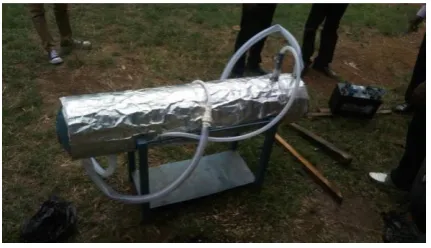
3.4.1 Field Test
The shell and tube heat exchanger (STHE) shown in figure 9 was subjected to field test after fabrication. The flow arrangement adopted for the design is the cross flow due to the greater log mean temperature it offers. One yard of 1¼ diameter hose was used to convey the fluid at the tube inlet and clipped to ensure the hose is firmly fitted to the heat exchanger inlet port. The hose connected to the tube inlet in turn connected to the outlet of the submersible pump submerged in the glycerin for easy flow of the fluid (glycerin) into the heat exchanger, while the hose connected to the outlet of the shell side fluid (hot water) was inserted in the retaining container. Similarly, another 1¼ one yard hose was connected to the inlet of the shell side fluid (hot water) and outlet of the cold side fluid which are gripped with a hose clip. The inlet of the shell side fluid (hot water) was connected to the outlet of the surface pump while the inlet of the pump was dipped in the hot water. The submersible pump which utilizes Alternating current (AC) was plugged into the AC socket while the surface pump was powered with a 12v battery. The hot water used for the experiment was obtained from a 25 litres cooking pot placed on the gas cooker. The observed temperature of the shell side fluid was 1000c,
while that of the tube fluid side (cold fluid) was 260c
before been allowed to flow into the heat exchanger. The temperature measurements were taken with the aid of an analogue thermometer.
At the end of the experiment, the heat transferred to the cold fluid increased by 60c while that of the hot fluid
reduced to 600c.
Fig. 9: Field Test Demostration of the STHE
3.4.2 Laboratory Test
The shell and tube heat exchanger (STHE) was also subjected to laboratory test after field test. The essence of this is to test the STHE on a large scale. The compartment carrying hot fluid was connected to the boiler so that there will be constant supply of hot fluid to the heat exchanger,
but could not be achieved due to the ineffectiveness of that machine (boiler). The STHE fabricated demonstration when connected to the faulty boiler is presented in figure 10.
Fig. 10: Laboratory Test Demostration of the STHE
IV. RESULTS AND DISCUSSION 4.1 Experimental Results
The results obtained from the experimental results are presented below:
Shell side fluid – Hot water Tube side fluid – Glycerin
Inlet temperature of hot water, 𝑇ℎ1= 1000𝐶 Outlet temperature of hot water, 𝑇ℎ2= 900𝐶 Inlet temperature of Glycerin, 𝑇𝑐1 = 260𝐶 Outlet temperature of Glycerin, 𝑇𝑐2 =?
Mass flow rate of Glycerin, 𝑚𝑡= 0.28𝑘𝑔/𝑠 𝑚𝑐 Mass flow rate of hot water, 𝑚𝑠= 0.07𝑘𝑔/𝑠 − 𝑚ℎ Thermal conducting of the material, kw = 16.26 W/m0C
The maximum flow rate through the tube, 𝑈𝑚𝑎𝑥= 0.82 𝑚𝑚/𝑠
Table 1: Thermal properties of shell-side fluid @ average temperature =𝑇ℎ1+𝑇ℎ2
2
S / N
Prope rty
Sy mb ol
Unit Values
95 (0C)
90 (0C )
85 (0C)
80 (0C)
75 (0C)
1 Spec. heat cap.
Cp j/kg/ k
4212 420 6
4201 4197 4193
2 Therm al condu ctivity
K j/kgk 0.67 7
0.6 75
0.67 3
0.67 0
0.66 7
3 Pradtl No.
Pr 1.85 1.9
6
2.08 2.22 2.38
4 Densit y
ℓ Kg/ m3
961. 5
965 .3
968. 1
971. 8
974. 7 5 Viscos
ity
𝜇 Kg/ m.s
0.29 8 E-3
0.3 15 E-3
0.33 3 E-3
0.35 5 E-3
https://dx.doi.org/10.22161/ijaems.4.6.4 ISSN: 2454-1311
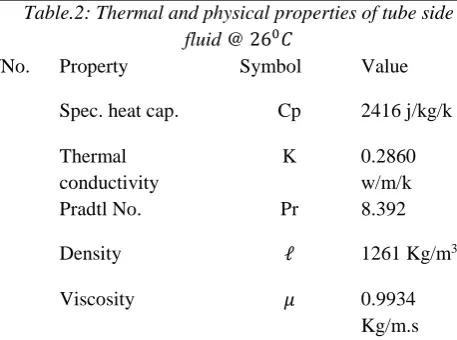
Table.2: Thermal and physical properties of tube side fluid @ 260𝐶
S/No. Property Symbol Value
1 Spec. heat cap. Cp 2416 j/kg/k
2 Thermal
conductivity
K 0.2860
w/m/k
3 Pradtl No. Pr 8.392
4 Density ℓ 1261 Kg/m3
5 Viscosity 𝜇 0.9934
Kg/m.s
4.2 Modeling Results
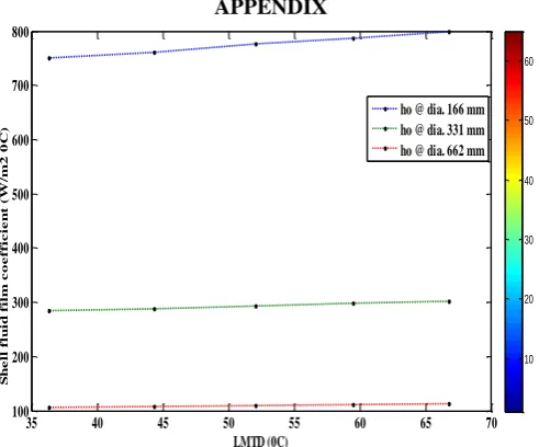
Fig. 11 showed the result obtained from the plot of shell fluid film coefficient (ho) against Logarithmic Mean
Temperature Difference (LMTD). It was observed that there is a direct relationship between ho and the LMTD. It
was also observed that ho decreases as the shell diameters
decreases.
It was observed from fig. 12 that as the shell diameter (ds)
increases, both the overall heat transfer coefficient (Uo)
and tube fluid film coefficient (hi) decreases.
It was observed from fig. 13 that as the LMTD increases the correction factor, irrespective of the tube sizes decreases. It was also discovered that the correction factor increases as the tube diameters increases.
V. CONCLUSION
The importance of mini shell and tube heat exchangers in industrial and other engineering applications cannot be underestimated. Hence in this project, a mini and shell and tube heat exchanger was developed on the laboratory scale using an optimized LMTD technique before embarking on the design and fabrication. The performance of the heat exchanger was assessed and evaluated to determine the optimum combination of design parameters for the transfer of heat between the two fluids involved in the STHE without mixing. It was discovered from the obtained results that the Bell-Delaware correlation produced the optimal value of shell fluid film coefficient over the other correlation techniques at any parametric iterations. Kern technique was the closest with correction factors between 0.8440 and 0.9850. There was also an inverse relationship between the shell fluid film coefficient and heat transfer rate. Though, irrespective of the shell diameters, the heat transfer rate is constant. But there is an inverse relationship between the LMTD and the heat transfer rate under any shell design parameters. In addition, there was a direct relationship between ho and the LMTD. While ho decreases
as the shell diameters decreases. It was observed that as the shell diameter (ds) increases, both the overall heat
transfer coefficient (Uo) and tube fluid film coefficient (hi)
decreases. The LMTD increases, the correction factor, irrespective of the tube sizes decreases. It was also discovered that the correction factor increases as the tube diameters increases. In conclusion, the Values of parameters of interest were also presented after rigorous mathematical calculations at optimal level. It was also discovered that Engineering Science Data Unit (ESDU) approach produced the optimal results required for the selection of tube fluid film coefficient over other correlations.
The design techniques and procedure adopted in this research work should be strictly adhere to by the Thermal and Fluid Engineers that are interested in the design of shell and tube heat exchangers (STHE) in order to come up with an optimum results. Other correlation techniques required for the determination of shell and tube fluid film transfer coefficients should be considered in the future research since this work is limited to only few.
REFERENCES
[1] Alfred, M.K. (2015). Article in Applied Thermal
Engineering. Retrieved from
www.researchgate.net/publication/279178955
[2] Alok, S., Prakash, K. and Deo, R.T. (2015). Design Procedure of Shell and Tube Heat Exchanger vol. 3, issue 12, pp. 116-119.Retrieved from
www.erpublication.org
[3] Arjun, K.S. and Gopu, K.B. (2014) Design of Shell and Tube Heat Exchanger Using Computational Fluid Dynamics Tools, Research Journal of Engineering Sciences, Vol. 3(7), pp. 8-16
[4] Asawari, B. (2016). An Overview of Shell and Tube Heat Exchanger Performance, International Journal of Research in Aeronautical and Mechanical Engineering, Vol.4 Issue 2, pp. 58-66.
[5] Cengel, Y.O. (2003) Heat Transfer A practical Approach (second edition), McGraw-Hill, pp. 667-716
[6] Dawit, B. (2014). Design and Development of Shell and Tube Heat Exchanger for Harar Brewery Company Pasteurizer Application (Mechanical and Thermal Design), Volume-03, Issue-10, pp. 99-109
www.ajer.org
[7] Gawande, S.H., Wankhede, S.D., Yeerrawar, R.N, Sonawane, V.J. and Ubarhande, V.B. (2012). Design and Development of Shell and Tube Heat Exchanger for Beverage. Mordern Mechanical Engineering, vol.
2, pp121-125. Retrived from
http://dx.doi.org/10.4236/mne.2012.24015
https://dx.doi.org/10.22161/ijaems.4.6.4 ISSN: 2454-1311
Scientific Engineering and Technology Research, Vol. 03, Issue 20 pp. 4181-4187.
[9] Jaydeep, B., Abhesinh, P. and Mahesh, V. (2013). A project Report on Designing and Analysis of Shell and Tube Heat Exchanger, pp. 1-36.
[10] Jurandir, P.P. (2012) Shell and Tube Heat Exchangers Basic Calculations, pp. 1-35. Retrieved from
www.PDHonline.org
[11] Kamaruddin, R. (2010). Report on Design of a Small Heat Exchanger (Shell-And-Tube Type), pp. 1-11. [12] Laxnipriya, S. (2014). CFD Analysis of Heat transfer
in a Helical coil Heat Exchanger with constant Wall Heat transfer Coefficient, pp. 1-40.
[13] Lokhande, H.K.. and Kumar, P.V. (2013). Review Paper on Design & Analysis for Shell & Tube Evaporator for Dairy Application, Vol 3. pp. 117-118. Retrieved from www.ijetae.com
[14] Ramesh, K. and Shah, D. P. (2003). Fundamentals of Heat Exchanger Design. New Jercy
[15] Sandeep, K.P. and Alkesh, M.M. (2012). Shell and Tube Heat Exchanger Thermal Design with Optimization of Mass flow rate and Baffle Spacing. Patel et al, International Journal of Advanced Engineering Research and Studies, vol. 2, pp. 130-135.
[16] Vindhya, V.P.D., Raj, R.V., Piyush, S.V. and Srivastava, A. K. (2014). Steady State Thermal Analysis of Shell and Tube Type Heat Exchanger to Demonstrate the Heat Transfer Capabilities of Various Thermal Materials using Ansys, Global Journal of Researches in Engineering: A Mechanical and Mechanics Engineering Volume 14 Issue 4 Version 1.0, pp. 24-30.
APPENDIX
Fig. 11: Shell fluid film coefficient against LMTD
Fig. 12: Heat transfer coefficient parameters against Shell diameters
Fig. 13: Correction factor against LMTD
35 40 45 50 55 60 65 70
100 200 300 400 500 600 700 800
LMTD (0C)
S
h
e
ll
f
lu
id
f
il
m
c
o
e
f
f
ic
ie
n
t
(
W/
m
2
0
C
)
Shell fluid film coefficient against LMTD
10 20 30 40 50 60
ho @ dia. 166 mm ho @ dia. 331 mm ho @ dia. 662 mm
100 200 300 400 500 600 700
0.03 0.035 0.04 0.045
Shell diameter, ds (mm)
h
e
a
t
tr
a
n
s
fe
r
c
o
e
ff
ic
ie
n
t
p
a
r
a
m
e
te
r
s
Overall heat transfer coefficient, Uo Tube fluid film coefficient, hi
10 20 30 40 50 60
35 40 45 50 55 60 65 70
0.84 0.86 0.88 0.9 0.92 0.94 0.96 0.98 1 1.02
LMTD (0C)
C
o
r
r
e
c
t
io
n
f
a
c
t
o
r
(
F
)
Correction factor for 12.7 mm tube Correction factors for 25.4 mm tube Correction factors for 50.8 mm tube