http://www.sciencepublishinggroup.com/j/ijsqa doi: 10.11648/j.ijsqa.20180403.13
ISSN: 2469-8156 (Print); ISSN: 2469-8164 (Online)
Evaluation of Effects of Change in Length of Carbon Fibers
on the Properties of Aluminum Based Composite
Syed Shehzad Raza
*, Tahir Ahmad, Mohammad Kamran, Mohammad Umar Manzoor,
Asma Salman, Barkat Ahmad, Rashid Sarfaraz Wattoo, Nouman Riaz
Department of Metallurgy and Materials Engineering CEET, University of the Punjab, Lahore, Pakistan
Email address:
*
Corresponding author
To cite this article:
Syed Shehzad Raza, Tahir Ahmad, Mohammad Kamran, Mohammad Umar Manzoor, Asma Salman, Barkat Ahmad, Rashid Sarfaraz Wattoo, Nouman Riaz. Evaluation of Effects of Change in Length of Carbon Fibers on the Properties of Aluminum Based Composite. International Journal of Science and Qualitative Analysis. Vol. 4, No. 3, 2018, pp. 74-82. doi: 10.11648/j.ijsqa.20180403.13
Received: April 27, 2018; Accepted: May 19, 2018; Published: June 12, 2018
Abstract:
The world wide need for the economical and excellent quality composite materials have promoted research in the field of composite materials. Among the metal based composite materials, aluminum matrix based composites have high strength, light weight, low cost and high wear resistance. So they are produced and used widely in structural applications, aerospace and automobile industries. Aluminum matrix composites were produced by varying weight % age of carbon fibers. Carbon fibers were electroless nickel coated. Stir casting has been used to incorporate carbon fibers into the molten melt. The composition of all 4 castings was same but the length of carbon fibers was changed as 4mm, 6mm, 8mm, 10mm respectively. Nickel coating produces high dispersion and stiffness due to precipitation of Al-Ni intermetallics. The mechanical and electrical properties of samples were analyzed. Mechanical testing has been performed by tensile testing, Microvickers hardness testing and Charpy Impact testing. Electrical property has been recorded by current voltage measurements. Mechanical properties have been improved by increasing wt% of reinforcement. By increasing voltage values current values also increases.Keywords:
Al Matrix Composite, Carbon Fibers, Stir Casting, Mechanical Properties, Electrical Conductivity1. Introduction
Day by day increasing demand of lightweight materials with high strength in the field of aerospace and automotive industries caused the development and use of Al based composites. The metal matrix composites are replacing the light metal alloys like Al alloys in different industries applications where strength, low mass and high energy savings are the priorities in the selection criteria of materials. The combination of properties like electrical, mechanical and chemical can be obtained by the use of different kind of fibers reinforcements like continuous, discontinuous, short etc [1].
The type of composites called Particle reinforced metal matrix composites (PMMCs) are used for structural applications due to their isotropic material properties, low cost and ability to be shaped by the use of different material
processing such as rolling, forging and extrusion for obtaining the finish products. However the features of heterogeneous material system in various forms of composites, precipitation hardened and dispersion strengthened alloys is not identified well. The ceramics reinforcements of materials like SiC, Al2O3, TiC, B4C and ZrO2 have given the new variety of particle composites. These additions increase hardness and thermal shock resistance [2]. Alexander et al. achieved improved properties by making composites with Al/BN, Al/B, and Al/Li3N [11]. K. Litchenberg et al. have obtained enhanced properties by adding ribbons of the metallic glass Ni60Nb20Ta20 as reinforcements and aluminum alloy AlSi12 as matrix [12].
than two reinforcements while general composites contains at least one reinforcement [3].
The purpose of producing these new materials is to idealize the base material by keeping the advantages of it but not disadvantages. This can be done by introducing or reinforcing a material in it with the properties that are not in base material. As the size or percentage of reinforced material increases it affects the properties like Tensile strength, Hardness, Electrical conductivity, Wear resistance of base material. However, there are other features such as cost, weight, post failure behavior and fatigue performance that sometime directs the designer to the processing method for the production of composite in order to adapt the material to the exact requirements of the structure under design. In the present work the size of reinforced material i.e. carbon fibers is changed to determine its effect on the base (Al).
The current research work has an aim to study the functional properties of carbon fibers and vanishing epoxy coating from carbon fibers as well as depositing electro-less nickel coating on carbon fibers. Stir casting has been performed to make final castings. Optical microscopy and SEM analysis of samples of composite has been done to notice the features of cast structure. Electrical conductivity and mechanical properties have been collected for analysis of developed composite [4-10].
2. Experimental Details
Carbon fibers are used where low stiffness, high conductivity and low weight is required. Aerospace &space were some of first industries to adopt carbon fibers. The high modulus of carbon fibers makes them suitable for structural applications replacing alloys such as aluminum and titanium. Weight saving carbon fibers provides primary reason for their adaptation in aerospace industry. Carbon fibers are usually obtained from the suppliers in the form of sheet, woven cloths and mats. Usually epoxy coating have been applied on carbon fibers for their ease of handling. Epoxy coating does not depict a strong adhesion with aluminum, so it must be taken away. Mats of carbon have been used in current experimental work and are shown in Figure1.
Figure 1. Chopped carbon fibers.
2.1. Degreasing
Carbon fibers were isolated from mat and cut into desired length 3.5 cm before degreasing. Epoxy coating was removed by acetone in soxhlet extractor. Temperature of soxhlet extractor was 85°C for 24h. 250 ml of acetone was used for every 8gm of carbon fiber. This type of soxhlet extractor has the capacity of 500ml.
2.2. Roughening
Degreased carbon fibers were cleaned in ultrasonic cleaner. Distilled water was used for this purpose until the solution was neutral. Carbon fibers were dried at 100°C until a constant weight is obtained. After this carbon fibers were oxidized in nitric acid at 30°C for 40-45 min. Roughened carbon fibers were rinsed in distilled water & dried in oven at 100°C until a constant weight in obtained.
Figure 3. Ultrasonic cleaner.
2.3. Activation of Carbon Fibers Surface
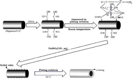
Activation of carbon fiber’s surface was done by dipping of 1g of roughened carbon fibers into 200ml plating solution for 12min followed by the absorption in NaBH4 solution. This process involves the catalytic sites formation on carbon fibers. After this process samples were washed with distilled water. The composition of the electro-less nickel plating solution used in both, the activation process and the nickel-plating process is given in the Table. pH of the solution was maintained at 8.5.
Table 1. Plating Solution Calculations.
Chemical Formula Concentration (g/L)
Nickel Sulfate Hexahydrate NiSO4.6H2O 35
Sodium Hypophosphite NaH2PO2 35
Lactic acid C3H6O3 18
Ammonium Chloride NH4Cl 25
Ammonia Solution NH3
2.4. Electro-Less Nickel Plating
Activated carbon fibers were put into plating solution at 70°C for 20 min. After this process coated carbon fibers were washed with distilled water and dried to a constant weight at 50°C. pH was adjusted by using ammonia solution.
Figure 4. Schematic of plating process for carbon fibers.
2.5. Mold Making
Molasses sand was plied for preparation of mold in foundry lab. Molasses sand and river sand were utilised in a particular ratio. Molasses act as binder in sand mold. Generally river sand has been mixed with 8 to 10 % of
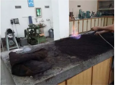
Figure 5. Molasses preparation for mold making.
Figure 6. Mold for casting.
2.6. Production of MMC
When a liquid metal is vigorously stirred during solidification, it makes a slurry of fine, spheroidal solids floating in the liquid. Stirring at high speeds makes a high shear rate, which is given to dilute the viscosity of the slurry even at solid fractions as high as 50 to 60% intensity. The procedure of casting similar slurry is said to be rheo-casting. Before casting short fibers, whiskers and particulates may also be incorporated into the slurry. This improved form of rheo-casting to manufacture near-net shape MMC components is declared to be compo-casting.
Compo-casting permits a good wettability b/w the reinforcement and matrix and imparts a homogeneous distribution in the matrix. A close contact has been achieved by doing continuous stirring. Low viscosity of the slurry and high mixing time imparts seasoned bonding. Temperature and shear rate minimizes the slurry viscosity. A good interaction b/w matrix and reinforcement has been achieved by increasing mixing time. Compo-casting is one of the most economical methods of fabricating a composite with discontinuous fibers. It can be done at temperatures lower than those conventionally used in foundry practice during pouring, resulting in reduced thermochemical degradation of the reinforced surface.
2.7. Casting
Pit furnace was used for melting of aluminum. Aluminum scrap (90-95% Al) was used for this purpose. Aluminum scrap was put in crucible and crucible was placed inside the pit furnace. Furnace was heated up to (700-800°C). Flux (Sodium) was also used in aluminum melting. Flux may have more than one function at a time. After melting degasser (Hexachloroethene) was used for degassing of gases. Plunger was used for the degassing purpose. When melting was completed crucible was taken out of the furnace. After slag removal finely chopped carbon fibers with required length were mixed in molten aluminum. A stirrer was used for continuous stirring of the mixture. At about 700 °C molten mixture was poured into the mould. After complete cool down casting was removed.
Table 2. Casting Compositions.
Casting sample Carbon fibers & length Wt.% (Grams)
Overall flux Wt.% (Grams)
Degasser Wt.%(Grams)
Aluminum Wt.% (Grams)
1 3gm (4mm) 0. 3-0.8% 0.3% 1497gm
2 3gm (6mm) 0. 3-0.8% 0.3% 1497gm
3 3gm (8mm) 0. 3-0.8% 0.3% 1497gm
4 3gm (10mm) 0. 3-0.8% 0.3% 1497gm
3. Results and Discussion
3.1. Tensile Testing
Universal tensile testing machine has been used to check various properties of MMC. Speed of loading was maintained at 2.000 mm/min. Results of broken tensile test specimens are shown in Fig.8. The specimens are placed sequentially.
Figure 8. Samples after tensile testing.
Table 3. Tensile test results.
Sample ID Force at peak (N) Force at yield (N) Strain at peak Elongation at peak (mm) Young’s Modulus (N-mm-2)
Ultimate Tensile Strength (N-mm-2)
1 2041 2100 1.30 0.96 3389.67 44.30
2 2009 2109 1.70 0.804 3896.40 47.55
3 3661 2187 2.72 0.425 3879.85 86.65
4 4017 2990 3.06 0.35 5050.33 95.07
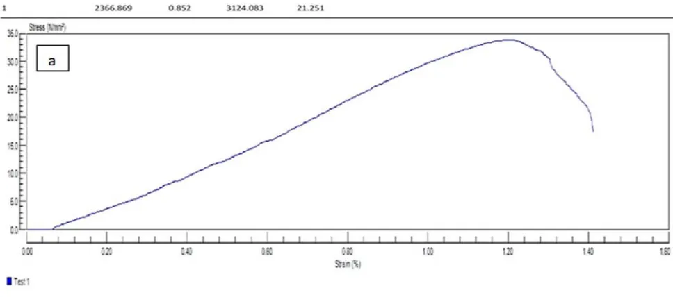
Figure 9. Tensile test results of carbon fibers with a length variation of a) 4mm b) 6mm c) 8mm d) 10 mm.
Above results of tensile testing show that tensile strength of samples increases with increase in length of carbon fibers. Porosity and other casting defects made samples little ductile. Above graph shows that ductility of samples is increased. Increasing the length of carbon fibers increases tensile
Figure 10. Ultimate tensile strength and elongation comparison of 4 samples.
3.2. Micro Vickers Hardness Testing
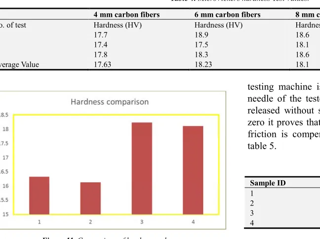
Microvickers hardness test was performed on vickers hardness tester using 495.5 N load applied for 5 sec. To
check any variation in samples test was performed in two ways one on flat surface and other on vertical surface. Results of both surfaces are shown in table 4.
Table 4. MicroVickers hardness Test Values.
4 mm carbon fibers 6 mm carbon fibers 8 mm carbon fibers 10 mm carbon fibers
No. of test Hardness (HV) Hardness (HV) Hardness (HV) Hardness (HV)
1 17.7 18.9 18.6 16.0
2 17.4 17.5 18.1 16.3
3 17.8 18.3 18.6 16.7
Average Value 17.63 18.23 18.1 16.33
Figure 11. Comparison of hardness values.
Its been noticed from the hardness values that 6 mm carbon fibers presence as a reinforcement exhibits peak hardness. So, this is the optimum composition which may be used as a reinforcement.
By increasing the length of carbon fibers in aluminum an increase in the hardness of MMC has been seen in Figure 11.
3.3. Charpy Impact Test
Charpy impact test is used to check the toughness of standardized impact test specimens. Pendulum impact testing machine is used for this purpose. Pendulum of the machine has heavy weight at the end. In first step pendulum is lifted to a starting position. Then the tester checks that whether the
testing machine is adjusted accurately. In order to do this needle of the tester is moved down word and pendulum is released without specimen. If the needle of tester indicates zero it proves that testing machine is in correct position and friction is compensated. Results of the tests are shown in table 5.
Table 5. Impact test results.
Sample ID Energy absorbed (Joules)
1 11.2
2 13
3 12.5
4 11.7
Above results show that specimens absorbed little energy due to ductility of samples. Porosity and other casting defects cause little ductility in sample. Ductility is due to agglomeration of carbon fibers in molten aluminum. Maximum energy is absorbed by sample 2 before fracture.
3.4. Electrical Conductivity Test
Table 6. Sample 1 (4mm length of carbon fibers).
Voltage (V) Current (A) Slope
0.1 0.23 1.339
0.2 0.38 1.339
0.3 0.46 1.339
0.4 0.56 1.339
0.6 0.72 1.339
0.7 0.89 1.339
0.8 1.18 1.339
0.9 1.27 1.339
1.0 1.38 1.339
1.1 1.46 1.339
1.2 1.78 1.339
Figure 12. Graph between voltage and current for sample 1.
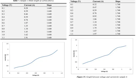
Table 7. Sample 2 (6mm length of carbon fibers).
Voltage (V) Current (A) Slope
0.1 0.28 1.640
0.2 0.39 1.640
0.3 0.46 1.640
0.4 0.59 1.640
0.5 0.78 1.640
0.6 1.07 1.640
0.7 1.25 1.640
0.8 1.34 1.640
0.9 1.43 1.640
1.0 1.62 1.640
1.1 1.91 1.640
Figure 13. Graph between voltage and current for sample 2.
Table 8. Sample 3 (8mm length of carbon fibers).
Voltage (V) Current (A) Slope
0.1 0.3 1.622
0.2 0.43 1.622
0.3 0.61 1.622
0.4 0.71 1.622
0.5 0.82 1.622
0.6 1.04 1.622
0.7 1.18 1.622
0.8 1.39 1.622
0.9 1.48 1.622
1.0 1.76 1.622
1.1 1.94 1.622
Figure 14. Graph between voltage and current for sample 3.
Table 9. Sample 4 (10mm length of carbon fibers).
Voltage (V) Current (A) Slope
0.1 0.32 1.748
0.2 0.47 1.748
0.3 0.59 1.748
0.4 0.78 1.748
0.5 0.92 1.748
0.6 1.06 1.748
0.7 1.18 1.748
0.8 1.54 1.748
0.9 1.79 1.748
1.0 1.87 1.748
1.1 1.97 1.748
Figure 15. Graph between voltage and current for sample 4.
3.5. Optical Microscopy
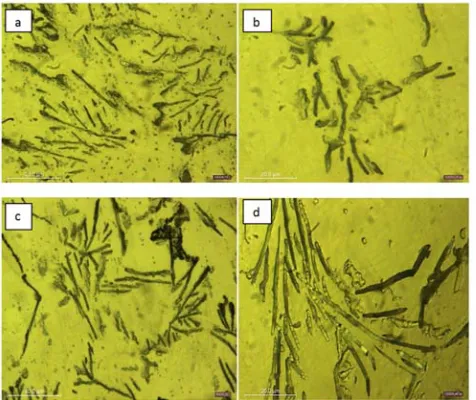
To observe the distribution of reinforcement in the matrix phase optical microscopy was done. Optical microscopy also reveals the casting defects which are not ignorable. Below are the images of 4 samples. These images were taken after etching the samples.
Figure 16. Optical microstructures of MMC having length variation of carbon fibers a)4 mm b) 6mm c) 8 mm d) 10 mm.
From the above images it can be observed that carbon fibers are properly distributed in aluminum matrix. As the length of fibers increases it becomes denser and bonded to aluminum phase. This bonding is due to the generation of AL-Ni interface which is developed due to nickel coating of carbon fibers. Nickel coating produces high dispersion and stiffness due to precipitation of Al-Ni intermetallics.
Some images show that there are also some other phases/ dark spots etc besides the distribution of carbon fibers. These are due to casting defects like porosity, gas pockets, solid shrinkage etc.
4. Conclusion
Aluminum composite reinforced with carbon fibers was developed. Carbon fibers were distributed almost homogeneously in the metal matrix. Nickel coating on carbon fibers improves wettability of fibers with aluminum. It assisted carbon fibers in mixing thoroughly into molten metal.
From tensile test results it is clear that with the increase in the length of carbon fiber keeping the percentage of fibers same, Ultimate tensile strength increases. Hardness of MMC also increased as for sample 1 the value of hardness is 16.33 HV and for sample 3 it is 18.23 HV. So with the increase in
the length of carbon fibers hardness also increases.
Electrical conductivity also increased with the increase in the length of carbon fibers.
On the other hand, manufacturing of these composites is not so easy as it is described. Some issues like coating of very thin carbon fibers, homogeneous mixing of fibers with molten matrix etc are the major difficulties in the way of development of Al-carbon fibers composites.
Acknowledgements
The authors are thankful for the financial support of The University of the Punjab, Lahore, Pakistan.
References
[1] http://machinedesign.com/materials/basics-aerospace-materials-aluminum-and-composites (Retrieved on 3/2/17).
[2] http://altairenlighten.com/in-depth/particulate-reinforced-composites/(Retrieved on 6/2/17).
[3] Robert M. Jones. Mechanics of Composite Materials (Materials Science & Engineering Series) 2nd Edition, ISBN-13: 978-1560327127.
[4] R. S. J. Eliasson. Applications of Al Matrix Composites, Metal Matrix Composites, July 1995, pp.3-36.
[5] C. M. M. Lancin. TEM study of carbon bre reinforced aluminum matrix composites, in uence of brittle phases and interface on mechanical properties, Nov 2000.
[6] J. I. S. et al. Effect of volume fraction of carbon fibers on wear behavious of Al/Al, OJC hybrid Metal Matrix Composites
[7] H. W. Liang Dong. Structures, Mechanical propertiesof carbon fiber composite octet-truss lattice, 2015, pp.26-33.
[8] J. R. A. M. Sanchez. Fabrication of Al Composites reinforced with carbon fibers by a centrifugal infiltration process, 2010.
[9] L. L. A et al. A simple Ni activation processes for P plating on C Fiber.
[10] C. Y. H et al. Optimum conditions of electroless Ni plating on C fibers for EMI shielding effectiveness of ENCF/ABS Composites, 30 May 1996.
[11] Alexander E. Steinman, Shakti Corthay, Konstantin L. Firestein, Dmitry G. Kvashnin, Andrey M. Kovalskii, Andrei T. Matveev, Pavel B. Sorokin, Dmitri V. Golberg, Dmitry V. Shtansky, Al-based composites reinforced with AlB2, AlN and BN phases: Experimental and theoretical studies, Materials & Design, Volume 141, 2018, pp 88-98.