Synthesis of Ba
0.5
Sr
0.5
Co
0.2
Fe
0.8
O
3
(BSCF) Nanoceramic
Cathode Powders by Sol-Gel Process for Solid Oxide
Fuel Cell (SOFC) Application
Yousef M. Al-Yousef, Mohammad Ghouse*
Energy Research Institute King Abdulaziz City for Science and Technology (KACST), Riyadh, Saudi Arabia E-mail:*[email protected], [email protected]
Received June 21, 2011; revised November 10, 2011; accepted November 20, 2011
Abstract
The nano ceramic Ba0.5Sr0.5Co0.2Fe0.8O3 (BSCF) powders have been synthesized by Sol-Gel process using
nitrate based chemicals for SOFC applications since these powders are considered to be more promising cathode materials for SOFC. Glycine was used as a chelant agent and ethylene glycol as a dispersant. The powders were calcined at 850˚C/3 hr in the air using Thermolyne 47,900 furnace. These powders were char- acterized by employing SEM/EDS, XRD and TGA/DTA techniques. The SEM images BSCF powder indi- cate the presence of highly porous spherical particles with nano sizes. The XRD results shows the formation of BSCF perovskite phase at the calcination temperature of 850˚C. From XRD line broadening technique, the average crystllite size of the BSCF powders were found to be around 9.15 - 11.83 nm and 13.63 - 17.47 nm for as prepared and after calcination at 850˚C respectively. The TGA plot shows that there is no weight loss after the temperature around 450˚C indicating completion of combustion.
Keywords:SEM/EDS, XRD, TGA/DTA, Ba0.5Sr0.5Co0.2Fe0.8O3 (BSCF)
1. Introduction
Solid oxide fuel cells (SOFCs) are considered as one of the most promising energy conversion devices that ex- hibit advantages such as high efficiency, system com- pactness and low environmental pollution [1-4]. The SOFCs are expected to be around 50% - 60% efficient at converting fuel to electricity. In applications designed to capture and utilize the system’s waste heat (co-genera- tion), overall fuel use efficiencies could top 80% - 85%. Since SOFC operate at very high temperatures ~1000˚C, it removes the need for precious metal-catalyst, thereby reducing cost. It allows SOFCs to reform fuels internally, which enables the use of a variety of fuels and reduces the cost associated with adding a reformer to the system. SOFCs are also the most sulfur-resistant fuel cell type; they can tolerate several orders of magnitude more sulfur than other fuel cell types. In addition, they are not poi- soned by carbon monoxide (CO), which can even be used as fuel. The traditional SOFC operate at around 1000˚C, which causes several problems such as; degra- dation of performance due to the formation of second phase, sintering of the electrodes and interfacial diffusion
between electrode and electrolyte. The current status of the development of a cell unit is based on yttria-stabi- lized zirconia (YSZ) solid electrolyte and electrodes consisting of Sr-doped LaMnO3 (LSM-Cathode) and Ni- YSZ cermet (Anode) [5,6]. The state-of-the art cathode material for high temperature (1000˚C) operation is LSM perovskite oxide. However, due to its poor ionic conduc- tivity, search of alternative cathode materials for inter- mediate temperature SOFC (IT-SOFC) is necessary. Therefore, the present trend is to develop reduced tem- perature SOFC technology which could be operated at below 800˚C. So much attention is being made for IT- SOFC in recent years [7-9]. Development of alternative cathode materials with adequate mixed ionic-electronic conductivity (MIEC) is needed to make the IT-SOFC technology successful. In spite of significant efforts have been put until now by various researchers, fundamental questions on the mechanism and kinetics of the O2 re- duction reaction and on the electrode behavior of LSM materials under fuel cell operation conditions still remain unsolved. The Table 1 shows the suitable materials for SOFC components [10].
Y. M. Al-YOUSEF ET AL. 100
Table 1. Suitable materials for SOFC components [10].
Component Requirements Preferred Materials Possible Alternatives
Electrolyte i > 0.05 S·cm–1 ZrO2-Y2O3
(3 - 10 mol%)
ZrO2-Sc2O3, CeO2-Gd2O3, (Sm2O3)
Cathode >100 S·cm
–1
(electronic/mixed) La1–xSrxMnO3 (La1–xSrx)Co, FeO3
Anode >100 S·cm
–1
(electronic/mixed) Ni/ZrO2-Y2O3
Ru/ZrO2-Y2O3 Ni/CeO2-ZrO2-M2O3
cermets
Interconnect Inert material, high temp. stability La1–x(Sr,Ca,Mg)xCrO3 High temp. alloys -
Manifold Non-volatile, inert Ceramics, metals -
Seal Non-volatile, inert Glass, glass-ceramic, Metal/ceramic -
cathode powers by glycine-nitrate process (GNP) me- thod for metal-supported SOFCs and studied their parti-cle size distribution, SEM, XRD, EIS measurement and electrochemical performance at 1073 K. The powder den- sity obtained were 0.91 W·cm–2, 0.77 W·cm–2, 0.69 W·cm–2 for the above powders respectively.
Park et al. [12] studied zinc-doped barium strontium cobalt ferrite (Ba0.5Sr0.5Co0.2–xZnxFe0.8O3–δ(BSCZF), x = 0, 0.05, 0.1, 0.15, 0.2) perovskite oxide powders for cath- odes of SOFCs application using the eyhylene diamine tetraacetic acid (EDTA)-citrate method with repeated ball-milling and calcining. They were evaluated as cath- ode materials for SOFC at intermediate temperature (IT- SOFCs) using XRD, H2-TPR, SEM and electrochemical tests. It is reported that the lowest doping of 0.05 (BSCZF05) resulted in the highest electrical conductivity of 30.7 S·cm–1 at 500˚C.
Chen and Shao [13] synthesized BSCF powders by combined EDTA-citrate complexing sol-gel process. The powder was calcined in air for 5 hr, ball milled and then pressed into bar-shaped pellets using a stainless steel die under a hydraulic pressure of 200 MPa and sintered at 1100˚C and evaluated their properties using XRD, ESEM and electrical conductivity relaxation (ECR) using Ar and O2 mixture. Based on chemical bulk diffusion coef- ficient (Dchem), the calculated ionic conductivity of BSCF reached 0.07, 0.25 and 0.96 S·cm–1 at 600˚C,700˚C, 800˚C respectively.
Sun et al. [14] prepared BSCF cathode materials for ce- ria-composite electrolyte low temperature SOFC application using sol-gel process with polyacrylicaced (PAA) with ad- justted pH with ammonia and they were evaluated with XRD, and electrochemical properties. It is reported that the maximum power density achieved was about 800 mW·cm–2 at 500˚C with Ni as anode and Sm0.2Ce0.8O2 (SDC)-car- bonate composite electrolyte and cathode as BSCF.
Recently a new cathode material Ba0.5Sr0.5Co0.8Fe0.8O3
(BSCF) reported [15], which showed excellent perform- ance as cathode material in conjunction with ceria-based electrolyte at reduced temperature compared with con- ventional cathode materials. Generally synthesis of BSCF is carried out by the traditional solid-state reaction methods [16] and other wet chemical methods [17-21]. These methods are time consuming and require high tempera- ture calcination (>950˚C) and long time to prepare the precursor, which faces the difficulties in preparing homo- genous material with good reproducibility. So to overcome such difficulties a sol-gel process is used generally for preparing the pure BSCF nano-powder for SOFC cath-ode application.
The main design requirements for SOFC Cathode Ma- terials [22] include: 1) High electronic conductivity, 2) Chemically compatible with neighboring cell compo-nents (electrolyte), 3) Stable in oxidizing environment, 4) Large triple phase boundary, 5) High ionic conductivity, 6) Thermal expansion coefficient similar to other SOFC materials, 7) Relative simple fabrication, 8) Relatively inexpensive materials.
In the present investigation, nano-crystalline cathode material of BSCF (5528) powders were prepared by the Sol-Gel process since it is a simple and more economical way of making nano powders for SOFC application. While the physical characterization of the powders were carried out using SEM/EDS, XRD techniques, the thermal prop- erties were carried out using TGA/DTA techniques.
2. Experimental Procedure
2.1. Preparation of BSCF Powders
The Ba0.5Sr0.5Co0.2Fe0.8O3(BSCF-5528) nano ceramic pow- ders were prepared by modified Sol-Gel Process [23-27] using Ba(NO3)2 (BDH), Sr(NO3)2 (BDH), Co(NO)3·9H2O
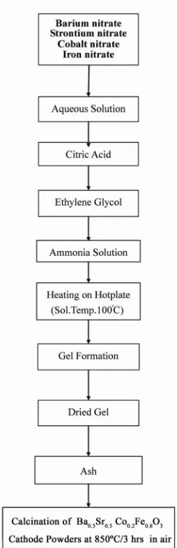
glycol (BDH), Ammonia Solution and distilled water. The precursor solution was prepared by mixing individual aqueous solution of the above chemicals in a molar ratio of 0.5:0.5 and 0.2:0.8 respectively (Table 2). To the mixed all nitrate solutions, required citric acid, ammonia solution and ethylene glycol were added. The citrate/ nitrate ratio used in the present experiments was 0.5. The solution was heated in a pyrex glass beaker on a hotplate using magnetic stirrer until a chocolate colored gel was formed. When heated further, the gel burns to a light and fragile ash. The ash was calcined at 850˚C/3 hr in air in a Barnstead Thermolyne 47,900 Furnace (USA). Figure 1 shows the flow sheet for the preparation of Ba0.5Sr0.5Co0.2 Fe0.8O3 powder using the Sol-Gel process. Table 2 shows the batch preparation of nano cathode materials (BSCF- 5528) by the Sol-Gel process.
[image:3.595.308.538.115.165.2]Figure 1. Flow Sheet for the preparation of Ba0.5Sr0.5Co0.2 Fe0.8O3 Nanoceramic cathode powders by Sol-Gel process [23- 27].
Table 2. Cathode (BSCF-5528) powders prepared by sol- gel process.
Sample no Cathode Powder With c/n Ratio
#77a,b Ba0.5Sr0.5Co0.2Fe0.8O3 0.50
#78a,b Ba0.5Sr0.5Co0.2Fe0.8O3 0.50
2.2. SEM/EDS Characterization
Small amounts of the samples were spread on adhesive conductive aluminum tapes attached to sample holders, coated with thin films of gold and examined with a FEI Quanta 200 Scanning Electron Microscope. An attached OXFORD INCA250 Energy Dispersive Spectroscopy (EDS) unit was used to determine area and spot elemen- tal compositions. Images at higher magnification were collected with a FEI Quanta 3DF SEM. Imaging was per- formed in secondary electron (SEI) mode using an ac- celerating voltage of 20 keV.
2.3. XRD Characterization
A part of the samples were analyzed with a PANnytical X’Pert PRO XRD for phase characterization. The X-ray diffractometry with CuK radiation at 35 kV and 20 mA was used for phase analysis with a diffraction angle 2 theta range 10˚ - 80˚ and particle size determination from X-ray line broadening technique using the following Debye Scherrer Equation [28]:
t 0.9 B cos Ø
where t = average particle size in nm, λ = the wave length (0.15418 nm) of Cu Kα radiation, B the width (in radian) of the XRD diffraction peak at half of its maxi-mum intensity (FWHM), Ø the Bragg diffraction angle of the line, and B is the line width at half peak intensity.
2.4. TGA/DTA Characterization
In order to determine the decomposition behavior of the BSCF Gel samples, around 7 mg - 8mg of the Gel sam- ples were loaded in an alumina crucible and put inside the thermo balance of TG machine (Perkin-Elmer Ther- mal Analysis Controller TAC7/DX, USA). The thermal decomposition behavior was studied up to 700˚C that was raised at a rate of ~10˚C per minute. TGA and DTA plots were presented.
3. Results and Discussion
3.1. SEM/EDS Characterization
[image:3.595.109.236.289.682.2]Y. M. Al-YOUSEF ET AL. 102
(a)
(b)
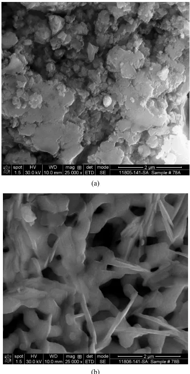
Figure 2. (a) SEM image of Ba0.5Sr0.5Co0.2Fe0.8O3 cathode powder as prepared (#77a); (b) SEM image of Ba0.5Sr0.5Co0.2 Fe0.8O3 cathode powder calcined at 850˚C (#77b).
(a)
(b)
Figure 3. (a) EDS of Ba0.5Sr0.5Co0.2Fe0.8O3 #77a (as prepared); (b) EDS of Ba0.5Sr0.5Co0.2Fe0.8O3 #77b (calcined at 850˚C).
(a)
(b)
Figure 4. (a) SEM image of Ba0.5Sr0.5Co0.2Fe0.8O3 cathode powder (#78a); (b) SEM image of Ba0.5Sr0.5Co0.2Fe0.8O3 ca- thode powder (#78b).
[image:4.595.69.275.80.483.2] [image:4.595.325.521.83.468.2]had not been combusted fully yet is shown in EDS in the as prepared BSCF powder. However, C content has been reduced in the calcined powders at 850˚C as seen in the EDS. Also this would further be reduced by increasing the calcination temperature.
3.2. XRD Characterization
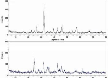
Figures 6 and 7 show the XRD patterns of the as prepared and calcined powders of Ba0.5Sr0.5Co0.2Fe0.8O3 at850˚C respectively. It is seen that as prepared powder is partly amorphous in nature. It is seen that the calcined powder has well crystalline perovskite phase of Ba0.5Sr0.5 Co0.2Fe0.8O3. These results are in agreement with the other authors reported elsewhere [14,15,19]. However, a minor amount of BaCoO3 phase is also present in the powders. This impurity will be disappeared and a single cubic perovskite structures may form when the calcina-
tion temperature is raised to ~1000˚C [18,19]. Also, this could be achieved by using pure metal nitrate chemicals (99.99%). Table 3 shows the average crystallite sizes of BSCF powders calcined at 850˚C. It is seen that the av- erage crystllite size of the BSCF powders were found to be around 9.15 nm - 11.83 nm and 13.63 nm - 17.47 nm for as prepared and calcined powders respectively. The results obtained here for BSCF (5528) are in the agree- ment with the other authors reported elsewhere [29] for BSCF using glycine/nitrate (g/n) ratio of 0.56. A number of factors are responsible for the nano size of the result- ing powders. Before the reaction, all the reactants are uniformly mixed in solution at atomic or molecular level. So during combustion, the nucleation process can occur through the rearrangement and short-distance diffusion of nearly atoms and molecules. When the combustion process takes place such a fast rate that sufficient energy and time are not available for long distance diffusion or
(a) (b)
Figure 5. (a) EDS of Ba0.5Sr0.5Co0.2Fe0.8O3 cathode #78a (as prepared); (b) EDS of Ba0.5Sr0.5Co0.2Fe0.8O3 cathode #78b (cal- cined at 850˚C).
[image:5.595.120.473.445.701.2]Y. M. Al-YOUSEF ET AL. 104
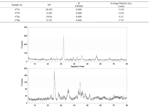
Table 3. XRD Data to determine the average particle size of the BSCF (5528) powders prepared by Sol-Gel.
Sample no. 2Ø FWHM B Average Particle size, t (nm)
#77a 24.432 0.680 11.83
#77b 32.08 0.600 13.63
#78a 24.84 0.880 9.15
#78b 31.92 0.468 17.47
Figure 7. XRD pattern of Ba0.5Sr0.5Co0.2Fe0.8O3 cathode powder (#78) (bottom: as prepared; top: calcined at 850˚C).
migration of the atoms or molecules which may result in crystalline growth. So the initial nano size of the powders is retained after the combustion reaction in sol-gel process. The average particle size of BSCF powder obtained here with c/n of 0.50 are much better than particle sizes ob-tained for BSCF using combination of PVA and urea as fuel [30].
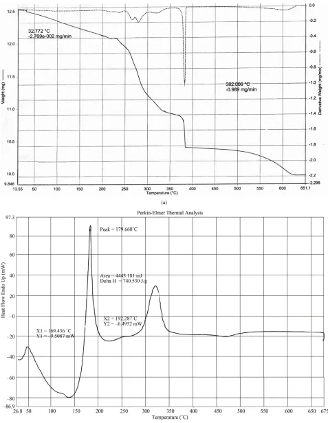
3.3. TGA/DTA Characterization
Figures 8(a) and (b) depict the TGA and DTA plots of the BSCF gels derived from precursor solution in the temperature range of 25˚C - 650˚C respectively. The endothermic peak observed for BSCF gel in the DTA curves at ~130˚C with small weight loss is due to evapo- ration of residual and hydrated water in the high tem- perature combustion process. It is seen from 180˚C - 300˚C that two strong exothermic peaks in DTA curves are observed which seemed to be associated with the decomposition/oxidation of the metal-chelates producing oxide phases. No further weight loss is observed after
temperatures reaching around 450˚C in the TGA plots which indicates the completion of combustion and for- mation of expected perovskite phase of BSCF. These results are similar to the other authors reported else- where [30] for BSCF gels.
4. Conclusions
The following conclusions are drawn from the present investigation:
The Ba0.5Sr0.5Co.2Fe0.8O3 (BSCF-5528) nano ceramic powders for cathodes were successfully prepared by Sol-Gel process with c/n ratio of 0.50.
SEM images of BSCF powders indicate the presence of highly porous spherical particles of nano size in the powders calcined at 850˚C.
XRD patterns show the presence of the perovskite Ba0.5Sr0.5Co0.2Fe0.8O3 phases.
(a)
(b)
[image:7.595.59.536.81.697.2]Y. M. Al-YOUSEF ET AL. 106
5. Acknowledgements
Authors thank Dr. Naif M. Al-Abbadi, former Director, Energy Research Institute, King Abdulaziz City for Sci- ence and Technology (KACST), Riyadh, Saudi Arabia for his encouragement and support during the course of this work.
Also, author’s thanks are due to Mr. Mahmoud Al- Manea, Dr. Shahreer Ahmad, Mr. Waleed Al-Othman and Mr. Abdul Jabbar Khan, Technology Center (TC), Saudi Arabian Basic Industries Corporation (SABIC), Jubail, Saudi Arabia for providing SEM/EDS analysis results of Cathode powder samples. Also, author’s thanks are due to Prof. Ahmed Basfer and to his colleagues Mr. Haitham Al-Gothami Technicians, Atomic Energy Research In- stitute (AERI) KACST, Riyadh, Saudi Arabia for pro- viding XRD analysis and TGA/DTA of Cathode powder samples.
6. References
[1] S. C. Singhal and K. Kendell, “High-Temperature Solid Oxide Fuel Cells: Fundamentals, Design and Applica-tions,” Elsevier, Oxford, 2003.
[2] T. A. Damberger, “Fuel Cells for Hospitals,” Journal of Power Sources, Vol. 71, No. 1-2, 1998, pp. 45-50. doi:10.1016/S0378-7753(97)02786-9
[3] T.-L. Wen, D. Wang, M. Chen, H. Z. Zhang, H. Nie and W. Huang, “Materials Research for Planar SOFC Stack,” Solid State Ionics, Vol. 148, No. 3-4, 2002, pp. 513-519. doi:10.1016/S0167-2738(02)00098-X
[4] S. C. Singhal, “Advances in Solid Oxide Fuel Cell Tech- nology,” Solid State Ionics, Vol. 135, No. 1-4, 2000, pp. 305-313. doi:10.1016/S0167-2738(00)00452-5
[5] N. Sakai, T. Kawada, H. Yokokawa, M. Dokia and T. Iwata, “Sinterability and Electrical Conductivity of Cal- cium-Doped Lanthanum Chromite,” Journal of Mater Science, Vol. 25, No. 10, 1990, pp. 305-313.
doi:10.1007/BF00581119
[6] N. Sakai, T. Horita, H. Yokokawa, M. Dokia and T. Kawada, “Oxygen Permeation Measurement of La1–xCax CrO3–δ by Using an Electrochemical Method,” Solid State Ionics, Vol. 86-88, 1996, pp. 1273-1278.
[7] R. N. Basu, F. Tietz, O. Teller, E. Wessel, H. P. Buch- kremer and D. Stöver, “LaNi0.6Fe0.4O0.3 as Cathodecon- tact Material for Solid Oxide Fuel Cells,” Journal of Solid State Electrochemistry, Vol. 7, 2003, pp. 416-420. [8] M. Koyama, C. Wen, T. Masuyama, J. Otomo, H. Fuku-
naga, K. Yamada, K. Eguchi and H. Takahashi, “The Mechanism of Porous Sm0.5Sr0.5CoO3 Cathodes Used in Solid Oxide Fuel Cells,” Journal of the Electrochemical Society, Vol. 148, No. 7, 2001, pp. A795-A801. doi:10.1149/1.1378290
[9] S. P. Simner, J. E. Bonnett, N. L. Canfield, K. D. Mein- hardt, J. P. Shelton, V. L. Sprenkle and J. W. Stevwenson,
“Development of Lanthanum Ferrite SOFC Cathodes,” Journal of Power Sources, Vol. 113, No. 1, 2003, pp. 1- 10. doi:10.1016/S0378-7753(02)00455-X
[10] “Solid Oxide Fuel Cell (SOFC)—Developments, Design, Materials and Current Status,” 14 August 2002.
http://www.azom.com/article.aspx?ArticleID1571 [11] Y. M. Kim, P.-K. Lohsoontorn, S.-W. Baek, J. Bae, “Elec-
trochemical Performance of Unsintered Ba0.5Sr0.5Co0.8Fe0.2 O3−δ and La0.6Sr0.4Co0.8Fe0.2O3−δ (LBCF) and La0.8Sr0.2MnO3 Cathodes for Metal-Supported Solid Oxide Fuel Cells,” In- ternational Journal of Hydrogen Energy, Vol. 36, No. 11, 2011, pp. 3138-3146. doi:10.1016/j.ijhydene.2010.10.065 [12] J. Park, J. Zou, H. Yoon, G. Kim and J. S. Chung, “Elec-
trochemical Behavior of Ba0.5Sr0.5Co0.2 ZnxFe0.8O3−δ (x = 0 ~ 0.2) Perovskite Oxides for Cathodes of Solid Oxide Fuel Cells,” International Journal of Hydrogen Energy, Vol. 36, No. 11, 2011, pp. 6184-6193.
doi:10.1016/j.ijhydene.2011.01.142
[13] D. Chen and Z. Shao, “Surface Exchange and Bulk Dif- fusion Properties of Ba0.5Sr0.5Co0.8Fe0.2O3−δ Mixed Con- ductors,” International Journal of Hydrogen Energy, Vol. 36, No. 11, 2011, pp. 6948-6956.
[14] X. Sun, S. Li, J. Sun, X. Liu and B. Zhu, “Electrochemical Performance of BSCF Cathode Materials for Ceria-Com- posite Electrolyte Low Temperature Solid Oxide Fuel Cells,” International Journal of Electrochemical Science, Vol. 2, 2007, pp. 462-468.
[15] Z. Shao and S. M. Haile, “High Performance Cathode for the Next Generation Solid Oxide Fuel Cells,” Nature, Vol. 431, No. 9, 2004, pp. 170-173. doi:10.1038/nature02863 [16] L. Tan, X. Gu, L. Yang, W. Jin, L. K. Zhang and N. Xu,
“Influence of Powder Synthesis Methods on Microstructure and Oxygen Permeation Performance of Ba0.5Sr0.5Co0.8Fe0.2 O3−δ Perovskite-Type Membranes,” Journal of Membrane Science, Vol. 212, No. 1-2, 2003, pp. 157-165.
doi:10.1016/S0376-7388(02)00494-5
[17] S. Lee, Y. Lim, E. A. Lee, H. W. Hwang and J .W. Moon, “Ba0.5Sr0.5Co0.8Fe0.2O3−δ (BSCF) and La0.6Ba0.4Co0.2Fe0.8 O3−δ (LBCF) Cathodes Prepared By Combined Citrate- EDTA Method for IT-SOFCs,” Journal of Power Sources, Vol. 157, No. 2, 2006, pp. 848-854.
doi:10.1016/j.jpowsour.2005.12.028
[18] H. Zhao, W. Shen, Z. Zjhu, X. Li and Z. Wang, “Pre- paration and Properties of BaxSr1−xCoyFe1−yO3−δ Cathode Material for Intermediate Temperature Solid Oxide Fuel Cells,” Journal of Power Sources, Vol. 182, No. 2, 2008, pp. 503-509. doi:10.1016/j.jpowsour.2008.04.046 [19] B. Wei, Z. Lu, S. Li, Y. Liu, K. Liu and W. Su, “Thermal
and Electrical Properties of New Cathosde Material Ba0.5 Sr0.5Co0.8Fe0.2O3−δ for Solid Oxide Fuel Cells,” Electro- chemical and Solid-State Letters, Vol. 8, No. 8, 2005, pp. A428-A431. doi:10.1149/1.1951232
[21] Y. Lin, R. Ran, Y. Zheng, Z. Shao,W. Jin, N. Xu and J. Ahn, “Evaluation of Ba0.5Sr0.5Co0.8Fe0.2O3−δ as a Potential Cathode for an Anode-Supported Proton-Conducting Solid Oxide Fuel Cell,” Journal of Power Sources, Vol. 180, No. 1, 2008, pp. 15-22. doi:10.1016/j.jpowsour.2008.02.044 [22] K. Wincewicz, J. S. Cooper, “Taxonomies of SOFC
Mate-rial and Manufacturing Alternatives,” Journal of Power Sources, Vol. 140, No. 2, 2004, pp. 170-173.
[23] M. Ghouse, A. Al-Musa, Y. Al-Yousef and M. F. Al-O- taibi, “Synthesis of Mg Doped LaCrO3 Nano Powder for Solid Oxide Fuel Cell (SOFC) Application,” Journal of New Materials for Electrochemical systems, Vol. 13, No. 2, 2010, pp. 99-106.
[24] Y. Al-Yousef and M. Ghouse, “Preparation of La0.6Ba0.4 Co0.2Fe0.8O3 Nanoceramic Cathode Powders by Sol-Gel Process for Solid Oxide Fuel Cell (SOFC) Application,” Energy and Power Engineering, Vol. 3, No. 3, 2011, pp. 82-391. doi:10.4236/epe.2011.33049
[25] Y. H. Lim, J. Lee, J. S. Yoon, C. E. Kim and H. J. Hwang, “Electrochemical Performance of Ba0.5Sr0.5CoxFe1−xO3−δ (x = 0.2 ~ 0.8) Cathode on ScSz Electrolyte for Interme- diate Temperature SOFCs,” Journal of Power Sources, Vol. 171, No. 1, 2007, pp. 79-85.
doi:10.1016/j.jpowsour.2007.05.050
[26] M. Ghouse, Y. Al-Yousef, A. Al-Musa and M. F. Al-Otaibi, “Preparation of La0.6Sr0.4Co0.2Fe0.8O3 Nanoceramic Pow- der by Sol-Gel Process for Solid Oxide Fuel Cell Appli- cation,” International Journal of Hydrogen Energy, Vol. 35, No. 17, 2010, pp. 9411-9419.
doi:10.1016/j.ijhydene.2010.04.144
[27] M. Ghouse, Y. Al-Yousef, A. Al-Musa and M. F. Al-O- taibi, “Preparation and Characterization of La0.7Ca0.3CrO3 Nano Ceramic Powder by Sol-Gel Process for Solid Ox- ide Fuel Cell (SOFC) Application,” World Journal of En- gineering,Vol. 6, No. 1, 2009, pp. 149-155.
[28] B. D. Cullity, “Reading, Massachusetts,” 2nd Edition, Addison-Wesley Publications, Boston, 1978, p. 102. [29] B. Liu and Y. Zhang, “Ba0.5Sr0.5Co0.8Fe0.2O3 Nano Pow-
ders Prepared by Glycine-Nitrate Process for Solid Oxide Fuel Cell Cathode,” Journal of Alloys and Compounds, Vol. 453, No. 1-2, 2008 pp. 418-422.
doi:10.1016/j.jallcom.2006.11.142
![Table 1. Suitable materials for SOFC components [10].](https://thumb-us.123doks.com/thumbv2/123dok_us/9241766.411605/2.595.56.540.103.265/table-suitable-materials-sofc-components.webp)