INTERACTIVE GRAPHIC SYSTEMS
t;DSn
teellllieDI Siteeifieatittil
Section Page Section Page
1 Introducing GDS II ... 1-1 4 Specifications ... 4-1
2 General Description ... 2-1 4.1 Database Features ... 4-1 4.2 Input/Editing ... 4-1 2.1 The Problems of VLSI ... 2-1 4.3 Display Control ... 4-3 2.2 The Solution - GDS II ... 2-1 4.4 Background Programs ... 4-4 2.3 Exploiting the Latest Technology ... , ... 2-2 4.5 Application Programming Tools ... 4-5 4.6 Hardware ... 4-6
3 System Operation ... 3-1
5 Software ... 5-1
3.1 Database Extensibility ... 3-1
3.2 Database Elements ... 3-1 5.1 Multiground RDOS ... 5-1 3.3 Database Construction ... 3-2 5.2 Database Management System ... 5-3 3.4 Menu Operations ... 3-2 5.3 GPL™ ... 5-7 3.5 Graphic Display ... 3-2 5.4 Background Job Management System ... 5-8 3.6 Character Display ... 3-3 5.5 Background Programs ... 5-10 3.7 Coordinate Interpretation ... 3-4
3.8 Data Entry and Edit ... ; ... 3-4 6 Hardware ... 6-1
3.9 Data Selection and Transform Operations ... 3-5
SECTION 1
INTRODUCING GDS II
In the intensely competitive semiconductor industry, rapidimplementation of new technology means success. This demands a production design system that works swiftly and without interruption. CALMA's GDS II meets these criteria.
GDS II is a turn-key interactive graphics system that has been developed with the insight provided by years of experience with its predecessor, GDS. It is a turn-key system, yet it also offers unprecedented support to those users with the imagination to enhance its extensive capabilities. Among the features and facilities described in the following pages are:
• 32-bit integer coordinate space to support VLSI
• Databases with information content extended beyond graphics • User definable extensions to databases
• Design station featuring alphanumeric as well as graphic display • Consistent, concise, and rich command language adaptable to
both novice and expert operators • GPL WM Programming Language
• Comprehensive design rule checking programs • Wide range of plotter support
• Exclusive All-Angle pattern generator support software • State-of-the-art electron beam pattern generator support
software
• Multiground, multitask, real-time disk operating system featuring:
• • Concurrent foreground and background activities • • Concurrent production and program development • • FORTRAN, ALGOL, DG/L, and assembly language user
programming
• High performance ECLIPSE computer featuring: • • Comprehensive instruction set
• • Extensive multiuser support hardware • • Memory mapping
• • High speed floating-point processor
GENERAL DESCRIPTION
2.1 The Problems of VLSI
GDS " is an advanced graphic system for the design of very large scale integrated (VLSI) circuits. Like its predecessor, GDS, GDS " provides a comprehensive turn-key solution to the problems of design, documentation, and artwork generation. But GDS " represents the next generation in interactivity, in efficiency, and in throughput.
VLSI presents several first order problems which cannot be solved by today's IC design systems. First, the required precision exceeds the capabilities of most existing systems. To resolve .1 micrometer features within a circuit 10 millimeters on a edge requires a resolution of 1 part in 105 - more than 16-bit integers can deliver. So GDS " uses 32-bit integer coordinates. Due to their uniform resolution, integer coordinate representations are, of course, superior to floating-point representations in applications requiring the generation of precision artwork.
Because of the complexity of VLSI, the sheer volume of data threatens to overwhelm a mini-computer based system. The GDS " Database Management System features unique mechanisms for data compression and data classification, minimizing disk requirements, both capacity and bandwidth.
The sheer volume of data poses a serious threat to background throughput. Background processes such as spacing checks and artwork generation involve sophisticated algorithmic processing and global sorting. To complete these tasks in an efficient and timely manner requires a powerful CPU and an efficient multiprogramming background facility which can make effective use of (relatively) large core configurations. The GDS II Background Processor provides significantly more throughput than its predecessor.
The sheer volume of data threatens to reduce the level of interactivity of
the system. After all, it should take much longer to select and manipulate data within a complex VLSI circuit. WRONG! The GDS " display software, coupled with the VMD, CALMA's unique display terminal, provides the ultimate in comfortable and productive man-machine interaction.
2.2 The Solution - GDS II
Building on the latest in hardware technology and its long experience in the integrated circuit design market, CALMA has developed a comprehensive new system to solve the problems posed by the new integrated circuit technology. The GDS II database provides the ultimate in precision (32-bit integer representation). The Command Processor provides the highest level of interaction ever offered on a minicomputer-based system. GPL /pM is available, along with a comprehensive collection of background processes to drive Pen plotters, Photoplotters, Optical Pattern Generators, E-Beam Pattern Generators, etc. Other
background processes include extensive Design Rules Checks. The
GDS " Background Processor provides for the efficient execution of multiple background tasks. For many tasks, GDS " will reduce the run time by large factors relative to GDS.
GDS " consists of a Central Processing Subsystem (including an ECLIPSE S/230 computer, an 80 Megabyte removable disk pack memory, a magnetic tape, and a system console) to which Design Stations, Plotters, and other peripheral equipment are attached. As many as six interactive, design stations may operate simultaneously, with minimal degradation in average system response time. At the same time, as many as three on-line plotters can be producing artwork at full rated speed, and GDS " can be writing a tape to drive an off-line plotter or pattern generator. These operations take place in full background mode, without interrupting input or editing.
To suit varying customer requirements, CALMA provides several input devices for GDS II work stations.
• CALMA 48-by-60 inch constrained-cursor digitizing table, with backlighting.
• Drafting-table-size tablet with puck and/or stylus. • Console with 12-by-12 inch Rand-type tablet.
All stations include a keyboard, and an alphanumeric CRT (for designer communication). All are equipped with an interactive graphic display: An 11 inch storage tube, a 19-inch storage tube, or CALMA's unique VMD. Station config~ration does not determine station function. Anything that can be done from one GDS II station can be done from all others. And GDS II can read-in GDS databases. Thus existing designs created on GDS can be maintained on GDS II.
2.3 Exploiting The Latest Technology
Building on the experience gained over the past six years, during which GDS has become the standard of the semiconductor industry, GDS II incorporates the latest in hardware and software technology, beginning with the ECLI PSE S/230 computer.
The Eclipse Computer:
The ECLIPSE's high performance starts with a fast microprogrammed architecture. A random-access stack and versatile interrupt system replace software routines. with high-speed hardware. A Floating Point Processor performs single and double-precision arithmetic at speeds matching those of large computers. Interleaving reduces memory cycle time. Effective memory speeds range from 200 to 640 nanoseconds.
2-2
into high throughput; throughput that lets GDS II handle the demanding tasks of interactive design, sophisticated rules checking, plotting, and user programming concurrently. Brielfy these features are:
• Comprehensive instruction set customized for operating systems and high-level language compilers. The set includes word, byte, and bit manipulation; extensive shift and logical operations; signed and unsigned integer multiply/divide; and block data movement.
• Extensive hardware stack mechanisms for fast subroutine linkage and context switching in real-time, reentrant environments.
• Memory Allocation and Protection with dynamic address translation, expansion to 512K bytes main memory, and write and address protection.
• High-speed Floating Point Processor featuring 32-bit and 64-bit formats and parallel processing.
• . Memory interleaving and overlapping that significantly reduce instruction execution times.
CALMA's Multiground RDOS:
GDS II is built upon an enhanced version of Data General's Real Time Disk Operating System (RDOS). This more powerful operating system is known as Multiground RDOS because it supports additional jobs beyond the "foreground" and "background" provided by the standard Data General RDOS. Up to sixteen (16) separate "grounds" or jobs may be run concurrently with the system, providing complete isolation and protection for each ground. This permits, for example, several different interactive graphics systems to run at the same time (e.g., GDS II and DDM) or interactive graphics concurrent with program development and debugging.
Among the standard features of RODS are Program Swapping, which allows up to five core images to be "pushed" to disk and them "popped" back and restored to execution. This permits multipass algorithms to be cleanly implemented in a manner that is transparent to the operator; also special subroutines such as sorting may be implemented as swaps so the entire core space of the ground is available for use.
The RODS file system provides a generalized means of accessing disk files, at the same time supporting device-independent programming for characteroriented devices such as the DECwriter, Line Printer, and Station Keyboard. Filenames in RODS may be from one to ten (10) characters in length and optionally may contain a one or two letter filename extension at the end. The filenames are referenced through directories which may be nested up to three deep.
Multiground RODS retains complete compatibility with Data General's RODS and therefore allows all the software products developed by Data General to be run without modification. Included are compilers for FORTRAN, ALGOL, BASIC, and DG/L. Text editors and a Macro Assembler are likewise available.
Multiground RODS includes custom I/O drivers for all of CALMA's hardware. This permits a high level generalized interface forthe graphics system eliminating the need to resort to bit level programming with critical timing conditions.
The VMD:
In addition to these second generation tools, CALMA has developed a new type of interactive graphics display which promises to provide a quantum jump in the level of user interactivity as well as a substantial improvement in overall system performance. Dubbed the Vector Memory Display (VMD) this device makes use of a vector memory and a digital TV imaging system. The result is a graphics display whose capabilities far surpass those of existing refresh displays, which use only one type of refresh memory (vector or raster).
refreshed. This approach results in a high-resolution, flicker-free image. In addition to the stored image, a graphics cursor is continuously displayed in write-through mode, so that it will not become a part of the stored image. Using a graphics tablet or digitizer as an input device, the user can point the cursor at objects on the screen and issue editing commands to the system to alter these objects or add new ones. On the whole this type of display has proved more than adequate for numerous applications in such diverse areas as integrated circuit and printed circuit design, cartography, and three-dimensional drafting, designing, and manufacturing.
However, the storage tube display does have one feature that limits its effectiveness in applications requiring a rapidly changing graphic presentation: the image cannot be selectively erased. Thus, viewing an altered graphics image requires erasing the entire old image and redrawing the entire new one. Although CALMA's storage tube display is many times faster than competitive displays of this type, applications exist for which the image cannot be repainted faster than the designer can think of what to do next.
To overcome this limitation requires a graphics display whose image is continuously being refreshed, so that when a graphic object is altered in the memory from which the display is refreshed, its image on the screen rapidly disappears and its altered image simultaneously appears, while the remainder of the image remains unchanged.
A display which refreshes the image directly from a "vector memory" meets this requirement. The display reads X-V coordinate and intensity information from the memory and "strokes" the indicated line segments onto the screen in connect-the-dots fashion.
This approach, however, introduces more problems that it solves. For one thing, the complexity of the image which can be displayed without perceptible flickering is fundamentally limited - by how far the display tube's electronbeam has to travel, how rapidly the beam can be deflected and modulated, and how rapidly the image disappears from the screen.
Various techniques could be used to sidestep these limitations, but not without creating further problems. For example, the length of the path traveled by the beam could be reduced by attempting to minimize the total length of the invisible segments, but the computational overhead would be substantial if not prohibitive. Likewise, the persistence of the tube's phosphor could be increased, but this would cause "ghost" images to remain on the tube for a longer time after they had been altered in the vector memory, thus returning to some extent to the basic limitation of the storage tube display. Moreover, as the deflection circuitry is pushed to its limits, difficulties in maintaining accuracy and repeatability are likely to manifest themselves, so straight lines appear other than straight and rectangles fail to close on themselves. Finally, since screen brightness and stroking speed are inversely related, any attempt to improve one parameter will compromise the other.
A display which refreshes the image from a "raster memory", or dot matrix, avoids the above problems. Flicker-free images can easily be generated, regardless of complexity, because the electron beam always travels the same path: a top-to-bottom sequence of closely spaced left-to-right lines, as in a commercial television set. The raster memory is used only to modulate the intensity of the beam.
Because the image-painting path is constant and relatively short, a bright image can be created; and because the path is so regular, the difficulties of maintaining accuracy and repeatability are vastly reduced. In addition, once the graphic vectors of the image have been "rasterized", i.e., converted to sequences of dots in the raster memory, the data is in the optimal order for displaying. The raster memory approach even makes it easy to create one image, erase a rectangular field within it, and then write another inset image in the vacated space. This can, of course, be done repeatedly if desired, creating a montage composite image impossible to achieve with a vector stroking display.
Unfortunately, displays which rely solely on raster memory for refreshing the image suffer from another basic limitation. Once a vector has been rasterized, there is no good way to deal with the resulting dots. If it is desired to remove only those dots corresponding to a given vector, one
2-4
the raster memory selectively. But this would in general remove too many dots. What is really desired is to remove only those dots which the given vector was solely responsible for inserting and to leave alone those dots which were also inserted by intersecting vectors. But this is impossible, since in the raster memory all dots look alike. As a result, after the given vector is removed in this way, all conceivable intersecting vectors should be rewritten into the memory. In the worst case this amounts to rerasterizing the entire vector image, which runs the risk of nullifying the reason for going to a refresh display technology in the first place: the ability to alter the image rapidly.
The ability to zoom in on a selected portion of the data is best achieved by erasing the entire raster memory and rerasterizing the vector data at a different scale factor. This procedure brings out file detail that is unapparent at small magnification because different points must be mapped into the same dot. The alternative method of zooming, mapping each dot in a portion of the raster memory into a square array of dots on the screen, is a poor substitute, because the resulting magnification does not entail increased resolution.
What's more the raster-memory-only display offers no easy solution to the problem of selecting graphical objects on the screen by pointing at them. After all, a dot is just a dot. By contrast, a vector-memory-only display, for all its faults, finds this task relatively easy. A light pen detects it, causing it to be identified to the system.
information, between zero and three words for attribute information, two words for the initial X-V coordinate pair, depending upon the representation mode. -Thus the number of words used per vector could vary between one and nine, depending on the nature of the data; a realistic average is probably closer to two than three. Up to four memory boards can be configured in a VMD, fO'r a total of 130,000 words, or roughly 50,000 vectors.
A command processor, which incorporates an 8085 microprocessor, handles all communication with the host central processing unit (CPU) and controls the operations of the various subfunctions of the pipelined display processor. In the input mode, polygon entities generated in the CPU are passed to the command processor through the memory update system to the vector memory. In the redraw mode, entities are fetched from vector memory, tested for overlap with the current display window, clipped to fit within the window (if need be), scaled, and imaged onto a portion of the raster memory. In the display mode, the screen is simply refreshed from the raster memory and the display processor is otherwise idle. In the identify mode, vector memory is searched at high speed and the header and attribute information pertaining to the polygon having a vertex closesUo the indicated XV point is returned to the CPU. The VMD generates the images of up to four cursors and one display grid in hardware, so that they need not occupy space in the vector memory; similarly, three types of dashed lines can be generated in hardware, so that the individual visible segments need not be stored separately. Under normal circumstances, in redraw mode, data are processed at the rate of one word (per vector memory board) every 300 nanoseconds, so that an entire drawing may be redrawn about 40 times a second, fast enough to give the impression of continuous movement on the screen. However, if the display window spans a large fraction of the data, the VMD redraw rate may be paced by the peak rasterizing rate, which is about 35 nanoseconds/dot along the major axis. Likewise, in the unlikely event that numerous diagonal vectors must be clip'ped to fit within the window, this process could momentarily pace the system. Sufficient data buffering is provided between system subfunctions to smooth out most
The raster memory used by the VMD features yet another unique memory board. It too was developed jointly by CALMA and Intel. This board contains an array of 512 x 512 bits of solid state memory. As the video monitor, which has a grid of 1024 x 1024 addressable points, is being refreshed, an interpolation algorithm, which operates in real time. is used to fill in the dots not explicitly stored in the raster memory. In summary, the CALMA Vector Memory Display, by exploiting the best of two different refresh graphic memory systems, affords the designer an unprededented level of performance in refresh graphics displays. Features like unlimited inset capability, continuous pan and zoom, instantaneous context switching, and hardware select give GDS " an unequalled capability in its intended role as a VLSI design system. The influence of the VMD on the overall design of GDS " is readily apparent. Menus are displayed on the screen, if desired, so that the designer never need load down at the tablet surface. All necessary command prompting is provided the instant it is needed and just as quickly erased when no longer required. Menus within menus can be used to explicate the valid choices available to the designer at any given time.
The designer can switch from viewing layer one of an integrated circuit mask set to viewing layer two - instantly, with no more than a token amount of assistance from the CPU. (By contrast, systems that use storage tube displays must rely on the CPU to read the entire disk area containing the drawing and extract the relevant information for redrawing. Clearly, the VMD approach leaves much more time for the CPU to service other graphics terminals and background tasks.) Likewise, one could view all lines of a given type, or all gates, or all contacts .. It's all a question of masking in the desired attributes. One of the most useful features enables the viewing of a large portion of an electronic circuit and simultaneously viewing in a graphic inset a highly magnified view of the same circuit, centered around the cursor position within the forementioned view. This arrangement proves
particularly useful in routing Signal traces, where one needs to be aware both of the details of local obstacles and of the general direction in which one is headed. Modifications to the viewing parameters can be made independently from other commands and, in fact, within them. This enables the designer to route a trace to a different layer and then view the new layer of traces in solid lines and the old layer in dashed lines, all without terminating the input command.
MPC (not available in initial release):
In addressing the problem of checkplotting within the context of a VLSI design system, it became apparent that a high-resolution matrix plotter such as the Versatec 8242 offers a highly desirable solution. Integrating a device such as the 8242 into an interactive graphics system presents immense problems. CALMA has presently under development an intelligent Matrix Plotter Controller (MPC), built around the same technology as the Vector Memory Display, that addresses and eliminates these problems.
Consider the plight of a system architect attempting to integrate a matrix plotter into an ineractive graphic system. A Versatec 8242 electrostatic plotter is capable of producing a 40.96" x 40.96" plot at 200 spots/inch in slightly less than 82 seconds - regardless of complexity. Such a plot is 8192 x 8192 spots which requires 4,194,304 16-bit words to be represented in memory. This is exactly 128 times the capacity of a 32K word minicomputer which might seem the logical choice to perform the rastenzation of data. Thus a 32K word minicomputer would require at least 128 passes of an unsorted drawing database to produce a plot image! Therefore, dedicating a minicomputerto the scan conversion task could at best be expected to produce a plot image in 128 times the view time. Thus, an IC that views in 10 seconds could take no less than 21 minutes to convert to a raster image. Other algorithms involving sorting, etc., introduce their own extensive resource requirements. A compute to plotting time ratio of over the order of 20 to 1 strongly suggests that the great speed potential of matrix plotters is an empty promise.
CALMA, however, seeking to realize the great performance and convenience benefits of matrix plotters for their customers, recognized
2-6
The ability to rapidly scan a plot file is the most critical requirement. The vector memory developed for CALMA's Vector Memory Display offers an attractive solution to this requirement. The MPC's vector memory utilizes a special purpose memory board, jOintly developed by engineers at CALMA and Intel Corporation. This board contains 65,536 16-bit words of solid state memory and can be accessed at a rate of one word every 300 nanoseconds. Each polygon entity stored within the memory requires two words for header information, two words for the initial X-V coordinate pair, and one or two words for each subsequent X-V coordinate pair, depending upon the representation mode. Thus the number of words used per vector could vary between one and five depending on the nature of the data; a realistic average is between one and two. Up to four memory boards can be configured in an MPC, for a total of 262,144 words, or roughly 150,000 vectors.
Since the data in the vector memory can be processed in approximately 25 milliseconds, to drive the Versatec 8424 at 100% of rated speed requires that only 3 lines of raster data be generated per vector memory scan. To realize the goal of driving the device at rated speed, the MPC attaches high-speed special purpose computational hardware to the vector memory in a pipelined architecture.
the vector memory, and have his area-filled plot delivered at full rated matrix plotter speed.
SECTION 3
SYSTEM OPERATION
The operations of the GDS II system encompass a large variety of tasks inaddition to simple digitizing. The shift in emphasis towards total design data bases, rather than simple graphics data bases, reflects the evolving requirements of the production environment as well as the design environment. The cabality to verify that final artwork conforms to design specifications, for example, requires that the information content of the data base be extended beyond strictly graphical data elements. Since the GDS " System meets the users' requirements in doing a great deal more than merely collecting coordinates, the operation of the system must be discussed accordingly. The system provides a framework for the data collection process which each customer or installation may extend as desired. Before any digitizing may be done, the user must decide what data is to be collected, how libraries are to be organized, and so on. Only in this way can the most effective utilization of the system be achieved. Accordingly, the discussion of system operation begins with data base considerations.
3.1 Database Extensibility
CALMA provides turn-key systems in many areas of application. The GDS II system can be applied to a number of 2D disciplines including integrated circuit and printed circuit design. CALMA tailors the GDS II system to a particular discipline by implementing specialized primitves, implementing specialized GPL II programs, implementing specialized background programs, providing standardized menus, and providing standardized data bases. Each of these capabilities can be extended by CALMA or the customer. Extensibility facilitates both evolutionary system development and customization to meet application and user specifications. Of particular importance is data base extensibility, i.e., the ability to add new kinds of data base design with at most only externally defined (not understood by the system) conventions being used to implement the storage of new information. The GDS II Database
Manager provides data base extensibility thus allowing the user to specify his own aata base which incorporates elements and properties unique to him and meaningful to the system.
3.2 Database Elements
In dealing with large quantities of data two kinds of distinct partitioning are required. The first kind of partitioning is spatial. This kind of partioning allows extreme flexibility in specifying combinations of partitions for use in most editing operations. The second kind of partitioning allows the graphical presentation of an object to be specified independently of the spatial partitioning. Spatial partitioning is implemented by the 64 layers of a drawing. Representational partitioning is achieved through the 64 datatypes assignable to any element of the data base.
The GDS II data base organizes data into classes of elements: (1) Paths - unclosed polygons with width
(2) Circuits - closed polygons (3) Srefs - structure references
(4) Arrays - structure references in a rectangular configuration (5) Text - describe the graphical presentation of paragraphs of text (6) Snap - specifies connect points
Graphic elements have layer and datatype associated with them. The layer may be between 1 and 64.
The datatype may be between 1 and 64. The path width may be any size.
3.3 Database Construction
A drawing in the GDS II System is defined as the contents of a library set. A library set is composed of a master library and a working library. Master libraries are defined by the user on a project or process technology basis. The master library incorporates the data base schema and therefore determines the kind of data elements that may be defined in a working library. The master library may include exemplars which specify default values for typical working library elements. While an exemplar might be thought of as a skeleton or pattern for the data element, the data in an exemplar is accessed by reference. This allows the default values to be overridden on an instance-by-instance basis and yet permits the default values to be easily edited. Nested references by elements in the master library to structures defined with the master library are allowed.
A working library is always associated with a master library. Except for references to the master library, the working library is self contained. The working library may define exemplars and data structures for reference by name just like the master library. Any component unique to the working library is presumable defined in the working library. In particular, it is not necessary to define a component externally just to reference the structure at multiple locations in the drawing.
Given that a master library has been created, the typical use of the system is to create or edit a working library. While more than one master library may exist with multiple users accessing different master libraries, the master library may also be shared. While the master library would be handled as a read-only file in such a circumstance, a working library is generally allowed to be accessible by only one user at a time. In
particular, multiple users cannot request update access to a single library.
3.4 Menu Operations
Menu Operations refer to the selection by the user of a string of characters to be processed just as if the user had typed them individually. Through this mechanism a unique "Ianguage" is implemented to interface operators or designers to the powerful primitives of the system. Because of GPL II programming these strings can be used to generate powerful, conditional, context dependent processing functions, complete with user prompts. At the other extreme each selection could generate just a single keystroke thus simulating a keyboard.
The implementation of the menu capability involves hardware and software selection mechanisms. Basically there are 512 different menu selections with as many as 64 characters definable to each. A 32 function button keyboard is provided, each key of which can select any of the 512 menu buttons. On a tablet or digitizing table a menu area is defined by a rectangular area divided into rows and columns of rectangles so that up to 512 of the menu buttons may be addressed by geometric position in the menu area. Additionally, the menu area may be shown on the VMD screen, so that when the cursor is in the area a selection may be made by moving the cursor to a user defined graphical presentation of a menu button and entering the selecting coordinate. By this method the user may keep his attention focused on the graphic display during system operation.
Creation and modification of menu buttons is easily achieved using the GDS II Text Editor (TED). Menu definitions may be saved and restored in RDOS files. Even though menus are easily produced, standard menus are provided to facilitate training.
3.5 Graphic Display
user-defined viewport(s) of the CRT screen. The viewport(s) may be located within the CRT window. The user can pan and zoom the data in the drawing file at any time, independent of digitizing or program execution.
The VMD has multiple cursors. Cursors may be used to trace the position of the digitizer (for coordinate entry) or the menu position for on-screen VMD buttons. Line types for paths/circuits include solid, dashed, dash-dotted, dash-dotted, or invisible. The VMD has clean selective erase, which means that delete operations as they occur will be echoed properly. The user may place construction lines, which are temporary and do not exist in the data base, but which may be erased instantly at any time the user desires.
The VDM data base window is the actual contents of the vector memory of the VMD. A radical move over the big drawing necessitates reloading of the VMD. Typically, the view window will only be a portion of the database window.
Panning is either manual or automatic; the manual mode is invoked by moving the viewport in any direction or centering it on a spot. Thesize of the viewport is also user defined upon manual pan. In automatic mode, the system moves the viewport with the cursor, so that the cursor is visible at all times, for ease of digitizing without interruption.
Zooming in and out is done relative to the center of the viewport. Zoom may be direct or continuous; for direct zoom; the user specifies the absolute or relative magnification factor. The relative magnification factor is used for saying "2X" or "0.3X". In the continuous zoom, the user specifies the upper and lower absolute magnifications. To start the zoom before assigned completion, the user presses either button.
The user will normally have two viewports, one depicting the global view of the drawing, the other showing the local vicinity of the cursor while digitizing. The local may be in automatic pan and zoom modes, and the global view might be in manual pan and zoom. Moving the digitizer sensor (puck) moves the cursors in both views. If the user moves the cursor out of the local viewport, the automatic pan will continuously move the local view around the cursor.
For lesser display devices, the VMD emulator directs output to process GDS " manual viewing commands in as much as the device can act like the VMD. The emulator requires an extra RODS ground and keeps the display file for the device on disk. The emulator cannot (in the case of the Tektronix CRT) partially erase, pan automatically, continuously zoom, or display multiple cursors.
Line Types include solid, dashed, dotted, dash-dotted, and invisible on the graphics display according to datatype specification. Four fill types are also defined and are displayable according to datatype specifications.
3.6 Character Display
The character display device supports the full ASCII character set, including lower case. The area of the screen is divided into two sections, a header in the first 3 lines and a scroll.
The header contains data which is updated continuously. The cursor location is displayed in user units on the top of the screen. This display is updated 10 times per second in parallel with the graphic cursor(s). The current time and date are also displayed in the header. The last line in the header is used for user-definable status information.
The remainder of the character display screen is used for a scroll with new lines being entered at the bottom of the screen. The scroll is being used to display input prompts, to log all commands executed, and to display any error messages.
In digitizing, if expected results do not appear on the graphic display, the user may redirect his attention to the alphanumeric display to find a record of the most recent interaction with the system. As a visual cue, all error messages will be output in bright characters.
able to enter one or more complete commands while the system is still executing the current command. By delaying the echoing of any pending input, any output follows the command line which causes that output. Error messages are also synchronized with the command line which causes the error. If an error is detected, any input which is pending (and has not been echoed yet) is discarded.
All coordinates are equivalent to character strings. If the cursor is in the menu area, the display on the character CRT is the text associated with the button as described above. If the cursor is in the drawing area, however, the display on the character CRT is the current location of the cursor. The values displayed are in user defined units and represent the net effect of any scaling or working grid.
While the user will normally use the pen as the principal input device in a digitizing situation, he does have recourse to the inputting or editing of text data.
3.7 Coordinate Interpretation
It is important to separate the notion of physical units and the capability to resolve those units for representational and manipulative purposes. A given horizontal or vertical line can be measured in any units that the user deems natural. The number of addressable coordinates along the line are restricted to a finite number sufficient for all resolution deemed necessary by the user. A change of natural unit usually doesn't require a change in coordinate resolution. Sufficient resolution is mandatory. Most coordinates fall on a regularly spaced pattern called a working grid. Occasionally intermediate points are desired or necessary for specifying such things as half grid width for centers of lines with width or circle centers, more uniform representation of a circular boundary, or perhaps even a good representation of a square of some grid width rotated 45 degrees (n *sqrt(2) is irrational, but an additional 45 degree rotation really ought to be correct).
Because of such reasons as these and more importantly the need for higher density designs in smaller physical units, the GDS II system allows the user to specify any convenient natural unit and has a resolving power of one his natural unit resulting in an immediate change in the presentation of coordinates.
Because most coordinates fallon a regular grid patter, the system provides a working grid capability with independent X and Y spacing and origined at any coordinate of the data base. Each coordinate entered by the user is forced to the nearest grid point. Grids can also be displayed on the graphic CRT. Grids are readily changed on command.
For those using a scaled source document the axes of the document can be independently specified at any angle to the table with as many as 11 reference points on each axis used to scale the document.
3.8 Data Entry and Edit
The GDS II Graphics Editor contains three modes for the purpose of lightening the input task. The first is conventional straight-line edges. The second is "orthogonal interpolation", which outputs the segment as two pieces, the horizontal piece and the vertical piece. The user may specify X-first or V-first. The final mode of input segment entry is "octagonal". The segments output are always horizontal, vertical, or 45-degree slant segments. Circles are additionally enterable as an interpretation mode by defining 3 points on the circumference, endpoints of a diameter, the center and the radius. Arcs are enterable as an interpretation mode in an even greater variety of ways.
Selection of items to change (one at a time) is done through the Graphic Editor via the get mode, which accepts one coordinate value.
Features possible for get mode: 1 ) get nearest sref 2) get nearest path
3) get nearest circuit
4) get nearest array
5) get nearest graphical element
6)
get next identified elementOne can choose the vertices to delete or add upon getting the polygon for edit. All operations done are abortable without the loss of information. Elements are created in "modes"(such as path mode, circuit mode, sref mode, ... ). This optimizes the amount of redundancy in user interaction. The modes are arranged in an English-language form for easy understandability, and ease of training.
Repetitious elements may be placed using copy.
Elements may be rotated, translated, magnified, or copied by the Graphic Editor.
Attributes of an element may be changed upon user command. (Such as layer, width, datatype, transformation ... )
Polygons:
Polygons are created by specifying path or circuit as the current input mode, and entering its vertices in the same order that they occur in connection, and terminated by a null input line.
Polygons may be unioned, intersected, logically not-ed, and xor-ed with each other.
Any portion (or all) of
a
polygon may be repositioned with an arbitrary transformation, such as stretch, rotate, or mirror. Closure is preserved. Rectang les:Rectangles are optimized for entry, as two-point forms. Structure References:
Structures are referenced by digitizing orgins in sref mode. User-definable transformations are saved as part of the structure reference. Snap Elements:
Snap elements are defined and edited as a set of points. Snap locations are used to relate a structure to locations in its referencing environment. Delete Features:
The user may delete points from the path/circuit in edit. The user may delete srefs or arrays.
The user may delete the last thing he created: a general undo function. The user may abort the current mode of entry.
The user may get a path/circuit and reopen it for edit, (then the user may undo vertices, or designate an arbitrary vertex or set of vertices for rapid deletion).
The GDS II Graphic Editor ignores trivial or redundant point cases to facilitate straightforward editing.
Exemplars:
The user may define any exemplar (property list) for part/circuit/sref/list/array binding.
Exemplar properties can be overriden by explicitly defined properties in a given element.
Properties in an element (layer, datatype, width, exemplar, reference, transform, etc.) can be changed by the user at any time.
3.9 Data Selection and Transformation
and still retain their identified property. Of course the identified group may be cleared at any time by the user.
"Templets" of layers are used to specify modifiable layers, addressable layers, and visible layers. Templets of data types are used to specify modifiable and addressable elements. Thus it is possible to restrict operations to any of 4096 (64*64) classes of elements or numerous other combinations. Templets are used to determine the four line types and area fill types for a given graphical presentation on the VMD display. The system makes use of many selection mechanisms by their appropriateness and ease of use. Layer and data type templets are used most often in restricting various operations. Three other major methods of data selection are: property selection, geometric selection,and identified g roup selection. All of these methods are supported by each of the editing commands.
Property selection is determined by the specification of property relational statement composed of property spec!fiers and literal values combined with =, <, >,<=,>=,and,or,not. Such a statement, if true, selects the associated data base element.
Geometric selection is specified by the closest vertex to a pOint, all vertices/structure references inside/outside a given closed region, or all circuits/paths which are wholly inside/partially inside/partially outside/wholly outside a given closed area.
Identified group selection can be used to process all elements that are/are not in the identified group.
Edits do not modify the identified group except for deletions. The identified group may be cleared at any time. To add to/delete from the identified group any of the above methods of selection may be used. Those selection methods addressing individual vertices may be used for stretching or deletion. More generally the addressing methods may be used to replace properties or to modify elements by translation, rotation, magnification, reflection, copying, deletion, changing layer, or changing data type.
3.10 Text Entry and Edit (TED)
The GDS II text editor is intended for many types of editing. The main types are:
1) Editing/Creating GPL II programs.
2) Editing/Assigning GDS II buttons for the menu. 3) Editing/Assigning text in a text element.
4) Editing/Creating Database Schemes.
Edit of a GPL II program is done by file name, edit of a button is done by button number, and edit of a text element is done by the location of the text element. Edit of a database schema is also done by name.
TED is a well-weathered Teco/style text editor, patterned after the one in RDOS.
Insertion/deletion of lines or characters is possible, as well as the powerful "change the next occurrence of this string to something else". Searching for any string of characters, possibly containing a carriage return, is possible.
3.11
Initiating Background Jobs
The GDS II Job Management System provides the facility for executing background jobs. Any executable RDOS program ("save file") may be invoked as a background job. Background jobs are non-interactive: once started up, they execute independently of the initiating station.
GDS-to-GDS II data conversion, and design rule checking programs. These are descri bed in detai lin Section 5.5.
User-written programs can also be run as background jobs. These programs can be written in Algol or Fortran and compiled using Data General compilers. They may also be written in assembly language. Access to the GDS " database (for reading, creating or changing data) is available to Algol programs and Algolcompatible Fortran subroutines, through the use of CALMA-written database access routines.
The user initiates and controls background jobs through a number of GDS " commands. These commands allow the user to initiate a job, terminate or suspend a job, change the priority of a job, and find out information about all jobs in the system.
3.12 Program Development
The GDS " System supports a wide range of capability in the development of user programs. The development of custom programs is an option that allows the system to be tailored to the user's unique requirements in either the data collection or data processing areas. While no special programs are required to use GDS /I System, even in many cases where the database definition has been extended, system enhancements may frequently be good investments.
The highest level programming language provided by the GDS /I System is the GPL I pM Programming Language. The GPL II Language is a general purpose programming language designed for interactive use. It is patterned after APL, a programming language which is widely available commercially. A common characteristic of both of these languages is definition of a complete set of array operators. With the GPL /I system, such operations as translation or rotation of a matrix representing a polygon is programmed as a single operation. Additional benefits include interactive execution and a full set of debugging aids.
The GPL II programming language is a superset of the GDS II command language. A set of commands can be transformed into a program with no changes whatsoever. Typically, the computational power of the GPL " Programming Language would be used to provide conditional execution of commands based on feedback from the system. On the other hand the
computational power of the GPL II language can be used, for example, to-evaluate arithmetic expressions in the command language without writing a program at all. A more significant use of the GPL " programming language is to implement programs which access values stored in user defined extensions to the data base.
The GDS " system supports several standard Data General programming languages. The most important of these is DG/L which is a derivative of ALGOL. Advanced users may choose to write DG/L programs that become part of the GDS " foreground system and may be referenced by the command language or the GPL /I programming language. The user also has the option of writing a DG/L program which interfaces with backgroung job supervisor if less demanding access to the data base is sufficient.
The advantage in using DG/L is that the source language is compiled directly into the ECLIPSE instruction set ratherthan being interpreted as is the case for the GPL /I programming language. Therefore, DG/L is a more suitable vehicle for programs with very extensive computational requirements. The disadvantage in using DG/L, as compared to GPL /I, is that interactive debugging at the level of the source language is not possible. The physical limitations of the machine in respectto how much memory can be addressed at a time are also much more in evidence using DG/L.
The GDS II system also supports FORTRAN as defined by Data General. An interface between FORTRAN and the GDS /I system can be implemented.
The GDS II System also supports the macro assembly language available from Data General.
may reattach his station to the GDS II foreground and resume normal operations.
3.13 Command Primitives
Since the system is menu-driven, the actual command language format is relatively unimportant to either the casual or production user. At least during the get-aquainted period with the GDS II system, and perhaps for some time thereafter, the users' experience with the command language will be limited to the extent of defining new menu buttons to tailor the system to meet his special requirements. It is anticipated that some customers will see fit to create a programming staff to see to it that they are making the most efficient use of the system.
Since most of the interaction with the system is at the menu level, it has been possible in the design of the GDS II system to treat the command structure as a language. That is, a consistent set of syntactical rules have been defined that are simple to learn. The syntax of a command does not depend on the particular command in question. This approach has been possible only because we have not been forced to be overly concerned about keystroke optimization at the command level.
In addition to a simple and consistent syntax, the basic philosophy of the command language design is to separate the data collection, data manipulation, data storage, and command iteration functions. This design has advantages if the user does nothing but use the standard system menu.
The data collection routine for defining a closed polygon shape is a primitive function in the command language. The most important use of this primitive, of course, is to digitize a polygon to be saved in the data base. The same function may be used in defining a region for area editing or group selection commands, however. Traditionally, there have been several tools implemented for use as operator aids in digitizing complex shapes. As editing procedures have become more powerful, the user is left to define a complex window with no help at all. The GDS II polygon data collection primitive can be used to support both data creation and editing functions. Using the same primitive, of course, guarantees that the specification of a complex shape is always handled in a consistent method.
The data manipulation routines are implemented as another set of primitives. These routines are special in that a context is generally desired while digitizing. The variables in the context are important only to the data creation primitive. In the original GDS system, for example, changing the mask layer affects the operation of several commands, e.g. SS, RT, CC, etc. In the GDS II system, such a change affects only one primitive. The concept of mask layer is important only when the data is saved, not in how the data is digitized.
Finally, command iteration is separated from the actual function. Therefore, it is just as easy to define a menu button that iterates collecting circles as it is to define a button that iterates collecting rectangles.
3.14 GDS II Accounting
SECTION 4
SPECIFICATIONS
GDS II is a unique and complete graphics system featuring design and production capabilities. The following specifications exhibit its VLSI capabilities as well as more generally applicable features.
4.1 Database Features
Elements:
Elements are the basic entities with a GDS II Database.
Elements are assigned "element types" as they are created. The set of element types may be extended by the user.
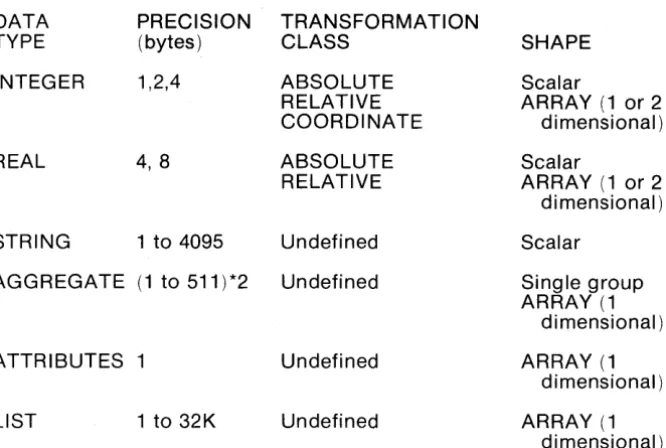
Elements are collections of properties or attribute-value pairs. The data type, precision, transformation class, and shape of properties may be defined. The set of properties may be extended by the user.
Exemplars:
Exemplars are elements that have a user assigned name.
Once associated with an element, an exemplar supplies default or common properties thereby facilitating editing and also compressing data.
Structures:
Structures are collections of elements.
A structure is composed of a "superstructure" and "infrastructure". The superstructure contains only the data required to relate the structure to
its external environment. The infrastructure contains the remaining information.
A structure may reference another structure in a hierarchial manner. Any reasonable number of levels of nesting structure references may be accomodated.
Libraries:
A library is a collection of structures, exemplars, schemas and tables for use by the Database Manager.
The number of structures in a library is limited only by available space. Each library is implemented as an RDOS file and may contain up to 33.5 million bytes of storage area.
A working library together with its associated master library comprise a library set.
4.2
Input/EditingCoordinates:
• Specified in user's natural units
• Natural and physical units changeable at any time • Independently defined X and Yaxes
• Independently specified X and Y grid, scaled in user units, at any X and Y origin, changeable at any time
• Grid display on graphic CRT
• Straight, orthogonal, and octagonal interpolation
• Coordinates specifiable by digitizing, snapping, literal specification, and relative specification
• In elements, coordinates are connected by linear or circular interpolation
• Resolution of 1 part in 4,294,967,296 Selection:
• 64 layers and 64 datatypes specify up to 4096 classes of elements • Templets of layers and other data types used to specify
modifiable, addressable, and visible elements • Selection by property of elements
• Selection by geometric relations
• Selection by membership in Identified Group • Selection is used to add to Identified Group Data Elements:
• Path - polygons with width • Circuits - closed polygons • Structu re references
• Arrays of structure references
• Text
• Snap coordinates • User-defi nable Graphic Editor:
• Any element may be selected or created • Properties of selected elements are modifiable • Points can be moved, added, or deleted
• Selected elements may be rotated, translated, reflected, magnified, copied, or deleted
Data Transformation:
• All elements addressed may be rotated, translated, reflected, magnified, copied, or delted
• If geometric selection is made individual vertices may be moved or deleted
• Transforms affect elements, and, except for deletion do not affect membership in the Identified Group
Text Editing:
• Editing operations are the same for all text strings in the system • Editing source may be a GPL II program, a menu button, any text
4.3 Display Control
Graphic Display - VMD:
The Vector Memory Display is used to display graphic data items, and, at the user's option, the current menu page. Data presentation features include:
• Line presentation may be solid, dashed, dash-dotted, or dotted • Line presentation is a unique property--not necessarily related to
layer
• Selected lines may be made invisible or blinked independently of presentation.
• Selected areas may be filled with pattern. Alphanumeric CRT:
The alphanumeric CRT is used to display current status in real time and record a log of all recent operator interactions. Status information includes:
• Current cursor location, in user units, continuously displayed • Current mode of interactive programs (if enabled)
Operator Interaction log includes: • Commands executed • Input prompts
• Error messages or results (if non-graphic) Window:
The VMD is loaded with all data to be manipulated in an edit session. The
result of this process, which may exceed SDK vectors, is termed the database window.
• Flexible data base window selector mechanisms: • • Selection by property value--e.g. layer(s) • • Selection by location
• Alternative handling of structure references:
• • Superstructure presentation--boundary and connection nodes
• • Infrastructure presentation--internal detail and nested reference
Viewports:
The VMD allows multiple, viewports into the data base window. Each viewport may be controlled independently of any other command in the system. Capabilities include:
• Increase magnification (and increase resolution) • Decrease magnification
• Specify magnification factor • Start/stop continuous zoom • Move viewport in any direction • Start/stop continuous pan Update frequency:
• Viewport changes are handled instantaneously by the VMD • All coordinates entered in the drawing area are marked
• All characters input as part of the current input request are echoed immediately
• All input typed ahead, prompts, error message, etc. are synchro-nized with the input commands
• Circuits are drawn as soon as each vertex is entered
• Paths are indicated by temporarily drawing the center line. The widened path is redrawn on completion
• Rectangles are drawn on completion • Deletions are performed on command
• Cursor location(s) on the VMD and
x-v
location displayed on the alphanumeric CRT are updated 10 times a secondDisplay Speed:
The GDS 1/ Operating System is capable of drawing vectors while loading the VMD at a rate of 3,000 - 4,000 vectors per second. Any change to the display (pan, zoom, translate, modify) affecting a simple element or a group of ele!llents is handled in 25 milliseconds. Assuming that the VMD memory is full, yields an effective transfer rate on the order of 100,000 to 200,000 vectors per second.
4.4 Background Programs
Design Rule Checks:
• Internal spacing checks • External spacing checks
• Layer-to-Iayer intrusion, extension, oversize and area of intersecton (not available in initial release)
• AND, OR NOT combinations of layers (not available in initial release).
• Area Merging (not available in initial release) Pen Plotters (on and off-line):
• Calcomp 936,960 • Xynetics 1100, 1200
• Versatec 8242 (not available in initial release) Pattern Generators (input as well as output):
• Mann 1600,2600,3000,3600 • Electromask 2000
• All-angle geometries may be processed Photoplotters (not available in initial release):
• Precision plot 2030
• Gerber S40, 632, 1232, 2032
E-Beam Pattern Generators (not available in initial release): • Etec MEBES
• Cambridge EBMF
4.5 Application Programming Tools
Graphics Programming Language: GPL IITM provides:
• Numeric and character data types and operations.
• Scalar, vector, matrix, and higher order array data structures. • Non-reverse list data structures.
• A full set of array and list processing primitives.
• An ALGOL-like control structure to facilitate structured programing.
• Full support of user programs--as operators or subroutines. • Interactive execution--disk calculator mode.
• Interactive debugging at the source language level. RDOS Programming Languages:
• FORTRAN • ALGOL • BASIC • DG/L
• Macro Assembler Utilities:
• Database Access Routines (FORTRAN, DG/L) • Editors
• Loaders • Debuggers
The combined facilities of GPL WM, FORTRAN, ALGOL, RDOS and the Database Access Routi nes offer the abi I ity to tai I or G OS II to a variety of graphic processing functions, including:
• Expansion of the command repertoire.
• Input/Output interface programming for special devices. • Format conversion and manipulation of graphic data bases. • Design rule checking.
• Simulation
• Test data generation
4.6 HARDWARE
Central Processi ng System: Computer
Instruction Length Hardware Accumulators Index
Add ress Modes Operator Control Memory Cycle Time Standard Memory Size Memory Fully Expanded Standard Arithmetic Element Standard Disk System: Transfer rate
Access time
Single drive capacity Expansibility
Optional Large Disk Subsystem: Transfer rate
Access time
Single drive capacity Expansibility
ECLIPSE S/230 16-bit and 32-bit 4
2 hardware, 16 memory
Direct, Immediate, Indexed, Extended, and Multi-level Indirect Addressing. Control panel with switch register
200-640 nanoseconds
128K, 16-bit words ( 4 stations) 256K, 16-bit words
High speed, single and double-precision floating point processor.
2.1 x 106 bits/sec
35 ms (average random move) 12.5 million words
One additional drive may be added
9.6 x 106 bits/sec
30 milliseconds (average) 50, 75, or 150 million words
4.6 HARDWARE (Continued)
Design Station: Tablet:
Size Resolution Accuracy Repeatability Input Device
Graphic Display (VMD): Vector Storage
Imaging System Display Points
Display Size (diagonal) Point Generation Vector Generation I mage Storage
Storage time per image Erase time
Vector draw time Controller
11" x 11"
100 lines/in. or 0.01 in. AO.01
AO.01 Pen Stylus
128K 16-bit words of solid state memory store approximately 50K 16-bit vectors.
Digital TV refreshed 30 times per second, regardless of information on display. 1024 x 1024
21" (53.34 cm)
Any addressable point intensified.
Hardware vector generation intensifies points between any two addressable points.
256,000 bits of solid state memory store value of each addressable point* Indefinite
1 ms
250 nanoseconds, plus 35 nanoseconds for each addressable point in major axis
4.6 HARDWARE (Continued)
Alphanumeric Display: Full ASCII, 96-characters Capacity
Features
Alphanumeric Keyboard: Full ASCII, 96-characters Repetition Rate
A-Z, a-z, 0-9, puncuation and graphic symbols 24 lines, 80 characters/line
Addressable Cursor Reverse Video Bright Characters
A-Z, a-z, 0-9, puncuation and graphic symbols 10 cps
SECTION 5
SOFTWARE
5.1 Multiground ROOS
The GDS II is built upon an enhanced version of Data General's Real Time Disk Operating System (RODS). This more powerful operating system is known as Multiground RODS because it supports additional jobs beyond the "foreground" and "background" provided by the standard Data General RODS. Up to sixteen (16) separate "grounds" or jobs may be run concurrently with the system, providing complete isolation and protection for each ground. This permits for example, several different interactive graphics to run at the same time (e.g., GDS II and DDM), or a interactive graphics concurrent with program development and debugging.
CALMA's Multiground RODS is arranged with a main-memory resident executive and system overlays residing on the disk. The executive must be resident in main memory storage before beginning continous and coordinated processing. The resident portion of RODS can manage overlays and buffers, process system calls, and service device interrupts. The system overlay modules are dynamically brought into main memory from disk storage as required. These perform operations such as device/system initializations, file management functions like file creation/deletion and accessing, code conversions, real-time clock and time-of-day clock control and spooling control.
RODS interacts with the user via the Command Line Interpreter (CLI). The CLI provides basic utility functions and file maintenance commands as well as a powerful means for passing parameters to programs that are invoked. Additionally, the CLI supports a nested macro facility that allows complex sequences of commonly used primitive commands to be parametrically generated in response to prompts from the user.
Memory Management and Protection:
A memory management and protection device has been developed for ECLIPSE computers. This option is supported under CALMA's Multiground RODS.
The option extends the maximum main memory configuration for a single central processor from 32K to 256K words. Within the framework of an executing program, two modes exist. The first mode is the absolute mode. In this mode, only the lower 32K is directly addressable. RODS resides in the low physical memory locations and executes in the absolute mode.
The second mode is called the mapped or user mode. In this mode, up to thirtytwo 102410 word pages of logical memory are mapped into real memory. User programs execute in user mode. Thus, they need not be aware of their actual memory locations and need not occupy contiguous pages of memory.
I/O units can be selectively protected against unauthorized user control. Areas of logical memory can be write-protected and validity-protected on a page basis, allowing the supervisor to load a reentrant routine for many users only once. Validity protection insures that only that portion of the user's program being used need reside in storage.
Any program operating in user mode uses a complete logical address space, which includes its private page zero and extends through its upper memory bound. This is determined by the requirements of the individual program prior to its execution. Managing the mapping device and constructing the user program as a logical address space is also the responsibility of RODS.