ENABLING NETWORK MOBILITY SUPPORT
Devan Rehunathan
A Thesis Submitted for the Degree of PhD
at the
University of St. Andrews
2012
Full metadata for this item is available in
Research@StAndrews:FullText
at:
http://research-repository.st-andrews.ac.uk/
Please use this identifier to cite or link to this item:
http://hdl.handle.net/10023/3205
2011
A thesis to be submitted to the
UNIVERSITY OF ST ANDREWS
for the degree of
DOCTOR OF PHILOSOPHY
I, Devan Rehunathan, hereby certify that this thesis, which is approximately 30,000 words in length, has been written by me, that it is the record of work carried out by me, and that it has not been submitted in any previous application for a higher degree.
date signature of candidate
I was admitted as a research student in October 2007 and as a candidate for the degree of Doctor of Philosophy in October 2007; the higher study of which this is a record was carried out in the University of St Andrews between 2007 and 2011.
date signature of candidate
I hereby certify that the candidate has fulfilled the conditions of the Resolution and Reg-ulations appropriate for the degree of Doctor of Philosophy in the University of St An-drews and that the candidate is qualified to submit this thesis in application for that degree.
date signature of supervisor
In submitting this thesis to the University of St Andrews we understand that we are giving permission for it to be made available for use in accordance with the regulations of the University Library for the time being in force, subject to any copyright vested in the work not being affected thereby. We also understand that the title and the abstract will be published, and that a copy of the work may be made and supplied to anybona fidelibrary or research worker, that my thesis will be electronically accessible for personal or research use unless exempt by award of an embargo as requested below, and that the library has the right to migrate my thesis into new electronic forms as required to ensure continued access to the thesis. We have obtained any third-party copyright permissions that may be required in order to allow such access and migration, or have requested the appropriate embargo below.
The following is an agreed request by candidate and supervisor regarding the electronic publication of this thesis:
Access to Printed copy and electronic publication of thesis through the University of St Andrews.
signature of candidate signature of supervisor
To my parents Narayanasamy Rehunathan and Shanthi Lim Hua Keng, whom I love very much.
To my aunt Jarojah Narayanasamy, without your love and support, none of this would be possible.
To Saleem Bhatti, my Sensei. Thank you for your wisdom and for taking a chance on me.
To Tristan Henderson, for always setting standards high and just out of reach.
To Greg Bigwood and Angus MacDonald, for making my time in St Andrews an unfor-gettable one.
To Ran Atkinson, for sharing your experience with me on a great number of things.
To Martin Bateman, for answering my questions in my first year and for free drinks in my second.
To Pan Hui, for giving me an opportunity to do research at T-Labs, Berlin.
To Boon-Chong Seet, my final year undergraduate supervisor and first co-author, thank you for encouraging me to complete my first academic publication.
To Markus Tauber, your "spanners" really tested my patience but in the end, I think they made me a better researcher.
To Fehmi Ben Abdesslem, for making me laugh and giving me a place to stay.
To Yi Yu, for hacking support, late night company and taking videos of me and my trolley at 4am.
To Savio Dimatteo, for late night dinners and advice on programming. Lets meet up in London.
To Iain Parris, for teaching me the value of knowing your stuff.
To Vincent Perrier, for creating Cloonix and letting me modify it.
To Davy Letham, Jim Park and Jose Marques, for all the technical assistance and hard-ware support.
The reader should note that while the major contributions in the design, analysis and im-plementation of these works were my own, I acknowledge the contribution and guidance of my fellow authors.
vNurse: Using virtualisation on Mobile Phones for Remote Health Monitoring.
Proc. HealthCom2011 - 13th IEEE International Conference on E-Health Networking,
Applica-tions and Services, 13-15th June 2011.
D. Rehunathan, S. Bhatti, O. Chandran and P. Hui.
The Study of Mobile Network Protocols with Virtual Machines.
Proc. SIMUTools2011 - 4th International ICST Conference on Simulation Tools and Techniques,
21-25th March 2011.
D. Rehunathan, S. Bhatti, V. Perrier and P. Hui.
Application of Virtual Mobile Networking to Real-Time Patient Monitoring.
Proc. ATNAC2010 - 2nd IEEE Australasian Telecommuication Networks and Applications
Con-ference, 31st Oct-3rd November 2010.
D. Rehunathan, S. Bhatti.
A Comparative Assessment of Routing for Mobile Networks.
Proc. WIMOB2010 - 6th IEEE International Conference on Wireless and Mobile Computing,
Networking and Communications, 11-13 October 2010.
D. Rehunathan, S. Bhatti.
Comparing Nework Protocols via Elimination of MAC/PHY Effects. (POSTER)
Proc. WOWMOM2010 - IEEE International Symposium on a World of Wireless Mobile and
Multimedia Networks, 14-17th June, 2010.
D. Rehunathan, S Bhatti.
Enabling mobile networks through secure naming.
Proc. MILCOM2009 - 28th IEEE Military Communications Conference, 18-21 October 2009.
D. Rehunathan, R. Atkinson and S. Bhatti.
Mobile Networks: Naming vs. Tunneling. (POSTER)
Proc. INFOCOM2009 - 28th IEEE International Conference on Computer Communications,
Joint Conference of the IEEE Computer and Communications Societies, 19-25th April 2009.
As computing devices become increasingly portable, it is becoming necessary to support
Mobilityas a core network functionality. The availability of devices such as smartphones,
tablets, laptops as well as wireless network infrastructure is opening up the possibility of usingNetwork Mobility to cater for multiple mobile nodes simultaneously. Network mobility may be useful in a number of mobile scenarios, where a large number of mobile nodes are moving in unison. A number of operational benefits stand to be gained by aggregating these nodes into a single mobile unit.
Unfortunately, the current state for network mobility support, especially in terms of net-work layer protocols, is limited. This is in part due to the inherent complexity of mobile network scenarios, the high cost of testing mobile network protocols in operational en-vironments and the difficulties in implementing such protocols.
2.1 Network Mobility with NEMO . . . 20
2.2 NEMO: VMN Initialisation . . . 20
2.3 NEMO: Testing Reachability . . . 21
2.4 NEMO: VMN to CN Route Optimisation . . . 21
2.5 NEMO: MR Handover . . . 21
2.6 Network Mobility with ILNP . . . 23
2.7 ILNP: VMN Initialisation . . . 24
2.8 ILNP: MR Handover . . . 25
2.9 ILNP: CN Update . . . 25
2.10 ILNPv6 Address Format . . . 26
3.1 Network Mobility with OptiNets . . . 34
3.2 OptiNets:VMN Initialisation . . . 35
3.3 OptiNets:Testing Reachability . . . 35
3.4 OptiNets:VMN to CN Route Optimisation. . . 36
3.5 OptiNets: MR Handover . . . 36
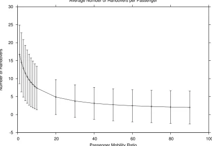
3.6 Passenger Handovers to Passenger Mobility Ratio . . . 39
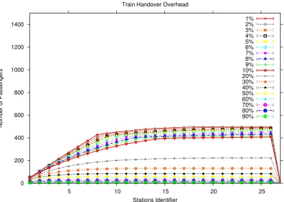
3.7 Total Number of Passengers . . . 40
3.8 Passenger Registration Load to Passenger Mobility Ratio . . . 41
3.9 Passenger Handover Load to Passenger Mobility Ratio . . . 42
3.10 20% Passenger Movement Ratio. . . 43
3.11 50% Passenger Movement Ratio. . . 44
3.12 90% Passenger Movement Ratio. . . 45
3.13 ILNPv6 Packet Overhead Per Person . . . 46
3.14 OptiNets Packet Overhead Per Person . . . 47
xii
3.15 NEMO Packet Overhead Per Person . . . 48
3.16 ILNPv6 Bandwidth Overhead Per Person . . . 48
3.17 OptiNets Bandwidth Overhead Per Person . . . 49
3.18 NEMO Bandwidth Overhead Per Person . . . 49
4.1 Mobile IPv6 Topology . . . 60
4.2 Cloonix Mobile IPv6 Equivalent. . . 60
4.3 NEMOv6 Topology . . . 61
4.4 Cloonix NEMOv6 Equivalent . . . 61
4.5 Nested Mobility Topology (Mobile IPv6 within NEMOv6) . . . 62
4.6 Cloonix Nested Mobility Equivalent . . . 63
4.7 Network Stack Model. . . 63
4.8 Real Testbed and Gate-1 used for Wired and Wireless experiments . . . 65
4.9 Gate-2 used for Wired and Wireless experiments . . . 66
4.10 Real Mobile Network . . . 67
4.11 Cloonix Virtual Throughput Results . . . 68
4.12 Cloonix Wired Throughput Results . . . 68
4.13 Cloonix Wireless Throughput Results . . . 69
4.14 Cloonix Virtual Packet Loss Results. . . 69
4.15 Cloonix Wired Packet Loss Results . . . 70
4.16 Cloonix Wireless Packet Loss Results . . . 70
4.17 Cloonix Virtual Jitter Results. . . 71
4.18 Cloonix Wired Jitter Results . . . 71
4.19 Cloonix Wireless Jitter Results . . . 72
5.1 Overview of Proposed vNurse Architecture . . . 78
5.2 Flow of Information in WBAN . . . 80
5.3 Network Consumption of Smartphone. . . 85
5.4 Throughput Variation against Packet Size and Bandwidth . . . 86
5.5 HTC Hero, Battery Level . . . 87
5.6 HTC Hero, Power Level . . . 88
5.7 Route taken by NEMO MR . . . 89
2.1 Summary of Early Classic Approach Protocols. . . 12
2.2 Use of names in ILNP and IP. . . 26
3.1 London Circle Line Data from Tubeprune [93]. . . 34
3.2 Passenger and train movement used in emulation. . . 35
1 Introduction 1
1.1 Network Mobility . . . 1
1.1.1 Applications of Mobile Networks . . . 2
1.1.2 Advantages of Mobile Networks . . . 3
1.1.3 Challenges in Network Mobility Support . . . 4
1.2 Motivation . . . 6
1.2.1 Complexity of Mobile Network Scenarios . . . 7
1.2.2 Difficulty in Implementing New Network Mobility Protocols . . . 7
1.3 Thesis Outline . . . 8
1.4 Thesis Structure . . . 8
2 State of Network Mobility Support 11 2.1 Host Mobility . . . 11
2.1.1 Phase One: Tunnelling . . . 11
2.1.2 Phase Two: Naming and Addressing . . . 14
2.2 Network Mobility . . . 17
2.2.1 NEMO . . . 17
2.2.2 ILNP . . . 19
2.2.3 LIN6-NEMO . . . 28
2.2.4 HIP-NEMO . . . 29
2.3 Summary . . . 30
3 Impact of Architecture Approach in Network Mobility Support 31 3.1 Introduction . . . 31
3.2 Route Optimisation for NEMO . . . 31
xviii
3.3 OptiNets . . . 33
3.4 Experiment. . . 33
3.4.1 General Equations . . . 36
3.4.2 Passenger Emulation . . . 38
3.5 Results . . . 39
3.5.1 Generated Passenger Mobility Traces . . . 39
3.5.2 Effect of Passenger Mobility on Overhead . . . 41
3.5.3 Effect of Passenger Correspondence . . . 42
3.6 Discussion . . . 43
3.7 Conclusion . . . 45
4 Studying Mobile Network Protocols with Virtual Machines 51 4.1 Introduction . . . 51
4.2 Problem . . . 51
4.3 A Comparison of Existing Tools . . . 53
4.3.1 Use of User-Mode Linux . . . 53
4.3.2 On the Use of Simulators . . . 54
4.3.3 On the Use of Testbeds . . . 54
4.3.4 On the Use of VMware . . . 55
4.3.5 On the General Use of Virtualisation . . . 56
4.4 Cloonix-Net . . . 57
4.4.1 Using Cloonix-Net . . . 58
4.4.2 Modelling traffic effects . . . 59
4.4.3 Modelling wireless effects . . . 60
4.5 Performance Analysis . . . 61
4.5.1 Experiment . . . 61
4.5.2 Testbed. . . 63
4.5.3 Results . . . 64
4.5.4 Discussion . . . 65
4.6 Conclusion . . . 66
5.2 Remote Patient Monitoring . . . 73
5.2.1 Wireless Body Area Networks . . . 74
5.2.2 Virtualisation on Smartphones . . . 75
5.3 Proposed Architecture . . . 76
5.3.1 Overview . . . 76
5.3.2 WBAN Component. . . 78
5.3.3 User-Mode Linux . . . 79
5.3.4 NEMO on Android . . . 81
5.3.5 3G connectivity challenges . . . 81
5.4 Evaluation . . . 84
5.4.1 Phase One: Feasibility Testing. . . 84
5.4.2 Phase Two: Operational Testing . . . 87
5.5 Conclusion . . . 87
6 Conclusion 93 6.1 Contribution and Summary . . . 93
6.2 Discussion . . . 96
Chapter 1
Introduction
As portable computing devices become more capable and affordable, they are becoming common items in our day to day lives. Smartphones, tablets and laptops can be found all around us. With regards to enabling mobility, it is efficient to provide network support not as individual mobile devices but as collections of mobile networks that contain mo-bile nodes (moving in unison). As the density of momo-bile computing devices and wireless networking infrastructure increase, mobile networking becomes more applicable to vari-ous scenarios. However, because network mobility is not supported as a core function-ality in the TCP/IP stack, additional mechanisms are required that implement network mobility support.
1.1
Network Mobility
The termNetwork Mobility Support, is used to describe how such mobile network
func-tionality may be enabled. Network mobility support is defined as:"...concerned with man-aging the mobility of an entire network. This arises when a router connecting a network to the Internet dynamically changes its point of attachment to the fixed infrastructure, thereby caus-ing the reachability of the entire network to be changed in relation to the fixed Internet topology. Without appropriate mechanisms to support network mobility, sessions established between nodes in the mobile network and the global Internet cannot be maintained after the mobile router changes its point of attachment. As a result, existing sessions would break and connectivity to the global
Internet would be lost."[1]
Mobile networks are networks that dynamically change their point of network attach-ment. The simplest case of a mobile network would consist of a mobile router (MR) and a mobile network node (MNN). As the MR changes its point of attachment, not only are all existing network connections of the mobile nodes unaffected but the MR and its MNNs are still connected to the external network, despite having changed topological location.
1.1.1 Applications of Mobile Networks
The study of network mobility support is becoming increasing relevant as computing devices are becoming increasingly portable. As a result, a growing number of users are able to access the Internet, while on-the-move. The rising popularity of devices such as smartphones and tablets, coupled with the adoption of wireless technologies such as IEEE 802.11 and 3G also reflect this. As a result, hardware manufacturers and network service providers are responding with a greater variety of powerful mobile devices and data plans. If this trend continues, it is likely that the desire for mobility and the ubiquity of portable computing devices and wireless infrastructure , will make it possible to realise the following proposed mobile network applications [2]:
1. Personal Area Networks or networks attached to people
2. Networks of sensors and computers deployed in vehicles
3. Access networks deployed in public transportation
4. Ad hoc networks connected to the Internet via a Mobile Router.
Personal Area Networks
Personal Area Networks (PAN) are networks which connect devices on a person’s body. These devices may use various communicating protocols such as Bluetooth1or ZigBee2
and may not necessarily use IP. Possible PAN devices could include smartphones , mu-sic players and wireless sensors. PANs may be used for inter-device communication or external communication.
Vehicular Sensor Networks
In such networks, the vehicles are themselves mobile networks, which provide network access to passengers or on-board sensors. These could include personal network devices of the driver such as a mobile phone or laptop. It could also include sensors within the car, such as a geo-positioning service (GPS) or performance sensors within the engine. The availability of a mobile power supply is also an advantage as there will be less power constraints.
Public Access Networks
Public Access Networks are networks that provide wireless network connectivity on pub-lic transportation (e.g. trains and buses). These networks allow IP-enabled devices to connect and use the network. The transport vehicle usually consists of one or more Mobile Routers and the number of connecting users may range from tens in buses to hundreds in planes and trains. Available infrastructure may be leveraged to assist con-nectivity in some cases.
3
Mobile Ad Hoc Networks
Mobile Ad Hoc Networks (MANET) are self configuring, decentralized networks formed of mobile devices that have no inherent infrastructure for routing. As a result, all nodes within the network act as routers and the network structure is dynamic. One possible example of mobile networks in this area is when passengers on a mobile train decide to form an ad hoc network to share files. There is also potential for network mobility support solutions to be extended to support additional functionality in MANETs. For example, in [3], it shows how network mobility may be used to support global reachabil-ity of MANET nodes. It is interesting to note that the similarreachabil-ity of some of the problems found in these two domains have led to potentially new areas of research with goals towards integrating network mobility and MANET support [4].
1.1.2 Advantages of Mobile Networks
Network Mobility is particularly applicable to the above scenarios because of the follow-ing advantages [5]: (i) reduced transmission power, (ii) reduced handoffs, (iii) reduced complexity, (iv) reduction in bandwidth and location update delays and (v) increased manageability. These benefits are accrued by aggregating multiple mobile nodes into a single entity.
With regards to (i), because the mobile router transmits to the fixed infrastructure on behalf of the mobile network nodes, conceivably, it allows the mobile network nodes to save energy as they transmit over a comparatively shorter distance to the mobile router as opposed to the fixed infrastructure themselves.
With regards to (ii), instead of each node having to manage itself, the mobile router man-ages the mobility of all the nodes within the network. As a result, at each handover, only the mobile router needs to handoff, all the mobile network nodes can maintain their existing connection with the mobile router regardless.
With regards to (iii), aggregating multiple mobile network nodes into a single mobile entity greatly simplifies aspects of mobility management. When the mobile network changes location, only the mobile router needs to configure a reachable address. This reduces the software and hardware complexity on the mobile network nodes and also makes it possible to have non-mobile aware nodes in the mobile network.
With regards to (iv), instead of all the mobile nodes sending a location update to the home agent, a single mobile router is able to update on their behalf. This results in less number of location updates and a reduction in bandwidth consumption for such messages.
1.1.3 Challenges in Network Mobility Support
Despite the potential applications and advantages to be gained in network mobility, these cannot be reaped with the current TCP/IP protocol stack, as it does not support network mobility as a core functionality. While limited forms of network mobility support do exist, the cost of research this field (e.g. experimentation, implementation) is very high. As a result, there are still a number of open challenges, due to the difficulties in enabling this.
Dominance of the Tunnelling Approach
Currently, the dominant network mobility protocol is the NEtwork MObility protocol (NEMO). It is the current IETF standard for network mobility support and is an extension of Mobile IPv6 [6]. Work on the NEMO protocol is currently being progressed in the IETF Mobility EXTensions (MEXT) working group [7]. This working group is working towards a unified mobility architecture for IP, by integrating NEMO with Mobile IPv6 (for mobile hosts), MONAMI [8] (for multi-homing) and IKEv2 [9] (for managing key exchange for security). The primary goal of this working group is to enhance IPv6 mobility such that it will be suitable for large scale deployment scenarios.
NEMO, like Mobile IP, uses aTunnelling Approachto support network mobility. This ap-proach uses two IP addresses instead of one, one is static and represents a home address and the other is dynamic and depends on a mobile host’s current location in the net-work. Both these IP addresses are managed by network entities that act as harbours for the mobile hosts and also as intermediaries, tunnelling packets to and from each other.
The popularity of this approach can be seen in the number of early mobility proposals such as [10] [11] [12] and [13]. Between 1991 and 1994, most major mobility solutions sub-scribed to the Tunnelling approach [12] and differed mainly in practical implementation (e.g. example protocols such as MosquitoNet did not implicitly require a Foreign Agent, even though this functionality was evident [14]). The research of this period culminated in what we know today as Mobile IP [15], which has been accorded Standard status by the IETF and is available in almost all major operating system network stacks.
NEMO-specific Challenges
Despite the popularity and maturity of the NEMO protocol, it is a basic support protocol and still contains a number of open research issues.
Sub-Optimal Routing
5
network path [16].
Mobile network prefix delegation
A NEMO MR requires one or more mobile network prefixes to setup a bi-directional tunnel between itself and its Home network. These prefixes are advertised to MNNs within the mobile network to ensure that traffic from the mobile network is forwarded and received correctly. Currently, these mobile network prefixes are assigned statically [5].
Nested Mobility
This occurs when there is more than one level of mobile network, i.e. when one MR, with its own mobile network, attaches to an existing mobile network. With NEMO, when this happens, forwarding tunnels of the inner level network are setup within the external mobile network’s tunnels. This results in an overall overhead of 80 bytes per packet and greater complexity in routing exchanges and establishing forwarding paths [17].
Optimised Handoffs
With NEMO, handoffs are handled by the MRs. When the MR moves to a new point of attachment, it has to re-establish its tunnel with its home network, to receive and send packets. This form of handoff is ahardhandover, as the previous tunnel is torn down and a new one is made. This could lead to loss of packets. Another form of mobility is the use ofsofthandovers, which allows for the setting up of the new tunnel before the old tunnel is torn down. This allows packet loss to be reduced (possibility eliminated altogether) during handover. However, soft handoff is not currently supported in NEMO [18].
Multi-homing
This capability allows for multiple connections to mobile entities. By being multi-homed, such mobile nodes or networks have more robust connectivity to the network. It is also easier for mobile systems to maintain and support ubiquitous connectivity across mul-tiple heterogeneous communication mediums. Such connectivity provides for redund-ancy, load-sharing and policy routing [19].
Network Pricing
Basic pricing models exist for mobile nodes, such as WiFi hotspots, where users pay a fee for a specific allotment of time on the network. Such models will not be economical for a mobile router, as it may contain multiple nodes within its network resulting in overall larger bandwidth consumption.
Alternative metrics to charge users, may include bandwidth consumption, whereby users pay only for what they use. However, this would be simple only if one user was respons-ible for a mobile network. This might arise, where the mobile network seeking network connectivity consists of different unrelated users.
res-ult in one bill.
Nested mobility, where mobile networks may connect to other mobile networks, also presents a problem with respect to pricing. It would be possible for mobile networks to pay for connectivity and subsequently charge other mobile networks to nest.
New Application Layer APIs
The usage of tunnelling to enable network mobility, hides mobility from mobile net-works, mobile nodes and correspondents. Alternative network mobility protocols, may make it possible for applications to detect mobility of the host, which would otherwise not have been possible with protocols such as NEMO.
As a result, new application layer APIs are needed that would make it possible for ap-plications to anticipate the effects of mobility and take suitable action. For example, in the case of non-seamless handovers, where some loss of connectivity and packets is to be expected, applications should sense when these events are about to occur and accom-modate to ensure no effects are noticeable for users.
End-to-End Security
IPsec Security Associations, include both the source and destination IP addresses. This means that if a node moves, or a network moves, then the existing IPsec Security Asso-ciations will cease to be valid. This constraint exacerbates existing concerns about the scalability of key management for IPsec devices. It also means that, regardless of what changes might be proposed for the Internet Key Exchange (IKEv2), support for mobility and multi-homing will remain limited and hard to deploy in the tactical environments where these capabilities are so crucial.
1.2
Motivation
7
1.2.1 Complexity of Mobile Network Scenarios
Dynamic Nature of Mobility
As mobile nodes and networks move, the network mobility support protocol has to en-sure that all existing connections are maintained. Mobile network scenarios are especially dynamic as a mobile network contains various kinds of MNNs. MNNs do not all have the same requirements. Some are fixed, they are referred to as local fixed nodes (LFN). Those that are mobile, are referred to as local mobile nodes (LMN) or visiting mobile nodes (VMN). The latter being mobile nodes from foreign mobile networks.
Issues of Scale
Mobile networks usually contain multiple nodes and may contain up to the hundreds, depending on the mobile network scenario. Network mobility support has to take into account network size and ensure that performance is not affected as the scale of the mo-bile network increases.
Nested Mobility
In the case of mobile networks, it should be possible for MRs to join other mobile net-works. This form of nested mobility may consist of mobile nodes as well as other mobile networks. Depending on the method used to enable network mobility, this may result in performance costs. For example, in NEMO, while sub-optimal routing is an acknow-ledged problem, it is made significantly worse with increasing levels of nested mobility.
1.2.2 Difficulty in Implementing New Network Mobility Protocols
Writing Code
Writing network protocols is hard. Existing network stacks such as the one found in the Linux kernel are known for their complexity. Writing network protocols in these envir-onments requires experience and a deep understanding, which is typically not available to the average network researcher.
Testing Protocols
1.3
Thesis Outline
This thesis argues that while the demand for mobile network support is rising, the cur-rent state of network mobility support is inadequate to meet this demand. It shows that new innovative techniques such as, the abstraction of architecture from engineering in simulation and the modification of existing virtualisation platforms can be utilised to better enable network mobility support.
This thesis looks at the following questions:
1. How can existing analytical approaches be leveraged to provide insight into mobile network application scenarios?
2. Can existing virtualisation platforms be modified so that their benefits may be ap-plied to mobile network problems, especially in the case reducing experimentation cost?
3. How may these new tools be effectively used with the current mobile network land-scape and technologies?
1.4
Thesis Structure
In Chapter1, I have introduced the concept of network mobility and its potential applic-ations, advantages and challenges. I have motivated the thesis and outlined the general arguments of the thesis, as well as its overall structure.
In Chapter2, I survey the current state of network mobility support. I introduce the Tun-neling Approach from its adoption in end-host mobility protocols to its eventual usage in network mobility support. I then explore an alternative approach, called the Naming Ap-proach. I conclude by saying that there is a growing need for network mobility support and that the cost of providing this support is currently high.
In Chapter3, my objective is to show that current network mobility support in its current form has some performance issues that suggest that it would be good to consider other architectural approaches. By looking at the impact of architectural approaches with re-gards to route optimisation in mobile networks, I conduct a comparative analysis of the cost of providing optimal routing, in terms of packet and bandwidth overhead, based on an emulation, using data from the London Circle Line metropolitan railway as a scenario. By looking at the impact of architectural approaches with regards to route optimisation in mobile networks, I show that these different architectural approaches to mobility offer significantly different performance trade-offs in routing for mobile networks, depending on the constraints of the network scenario.
9
existing tools and conclude that there is space for a new one. I then introduce Cloonix-Net and show how it may be used for mobile network scenarios. Finally, I evaluate Cloonix-Net by comparing its performance to that of a real testbed.
In Chapter 5, I extend my work in the previous chapter and demonstrate how mobile network support may be easily enabled and used in an innovative way. I first make the case for the usage of mobile networking in E-Health networks. I then provide an overview of my proposed architecture and its operation. I then proceed to implement it in real-life and evaluate the feasibility of such an approach. I concentrate on enabling the mobile router (MR) and on performance issues, such as the impact on battery life.
Chapter 2
State of Network Mobility Support
In this chapter, I survey the current state of network mobility support. In the first sec-tion, I look at the fundamentals of mobility and its key objectives. I then explain how these objectives are achieved at the Network Layer. I look at the evolution of the Tunnel-ling Approach and its significance to Mobile IP and NEMO. Subsequently, I explore the Naming Approach and alternative proposals to network mobility support.
2.1
Host Mobility
The historic development of end-host mobility solutions can be broadly categorised into two phases. The first phase includes the period leading up to and including the stand-ardisation of Mobile IP by the IETF. The second phase carries on from the first phase till today. These two phases are characterised by the types of end-host mobility proposals which can be categorised into two distinct approaches, theTunnellingapproach charac-terised by phase one and theNamingapproach characterised by phase two.
2.1.1 Phase One: Tunnelling
Representative of this period of research in mobility is the Tunnelling approach or what I will refer to as theClassic Mobility Approach. This approach uses two IP addresses in-stead of one, one is static and represents a home address and the other is dynamic and depends on a mobile host’s current location in the network. Both these IP addresses are managed by network entities (usually a Home Agent and a Foreign Agent), that act as harbours for the mobile hosts and also as intermediaries, tunnelling packets to and from each other. This is of course a very broad description and there can be many varieties of implementation that all use this approach.
The Tunnelling approach is a result of a practical solution adopted to enable mobility. There is no fundamental restructuring of the underlying semantics of the Network Layer. This approach reuses existing entities to get round the problem of addresses changing due to mobility. It is a unique example of the flexibility of the Internet. There are usually numerous solutions to a particular problem and each has its own advantages and disad-vantages. For the case of the Tunnelling approach, one may argue that it does not resolve the crux of the problem. However, the advantage is that, this solution does not require
any changes to the current protocols being used and is a relatively quick and simple fix, to what could otherwise be a complex solution with many implications.
The popularity of the Classic approach can be seen in the number of early mobility pro-posals such as [10] [11] [12] and [13]. The research of this period culminated in what we know today as Mobile IP [15], which has been accorded Standard status by the IETF and is available in almost all major operating system network stacks. Unfortunately, this protocol has not been widely accepted, as seen by its rare deployment and the fact it is usually not turned on by default.
Between 1991 and 1994, a substantial number of mobility solutions subscribed to the Classical mobility approach [12] and differed mainly in practical implementation (e.g. example protocols such as MosquitoNet did not implicitly require a Foreign Agent, even though this functionality was evident [14].) [20] analysed the protocols architecturally and distilled them down into the specific functionalities required such as a Forward-ing Agent, a Address Translation Agent and a Local Directory. It described the Classic approach as a two tier addressing scheme. It also distinguished mobility as an Internet Naming and Addressing Problem and asserted that as a result, mobility was best handled at the Network layer.
Another survey paper is [21], which did a detailed comparison on of existing mobility proposals based on the criteria of: performance, security, deployment, scalability and robustness. [22] took a different approach by analysing the scope of mobility possible with each protocol, and focused on analysing how well each protocol scaled. It also did a comparative analysis with system parameters although not much detail is given. It compared the mobility solutions in terms of design implications, with an emphasis on system performance analysis rather than an architectural one.
Regarding the implementation of mobility within the network, [23] asks the fundamental question of how best to support mobility and revisited the TCP/IP layer. At the network layer, it used two examples, Mobile IP (Classic Mobility Approach) and LIN6 (Split Loc-ator/Identifier Approach) only. It ends with a comparison of the different paradigms of Internet mobility support, the functional and performance aspects, as well as the changes required for implementation of the solutions.
Protocol Layer Characteristic Entities
MosquitoNet Network Layer Mobility Aware MH, HA (IP in IP) Software Entities
IMHP Link Layer " MN, HA, FA, CN
(ARP Gratuitous)
Harvard System Network Layer " MN, HA, FA, CN (IP in IP)
Columbia " Embedded Mobile MSR
Router Network
Sony Scheme " Virtual & Physical Layer Modified Router Migrate Transport Layer TCP Migrate Option FQDN & Connection ID
13
Mobile IP
Mobile IP is a mobility extension of the existing Internet Protocol. Originally called IP Mobility Support for IPv4, it was defined in [24] then updated in [25], and subsequently [26]. The following section is a direct summary from the referenced articles, and is still in the process of being summarised.
Mobile IP has the following key features [27]:
1. mobile devices can change their physical network attachment method and location while continuing to use their existing IP address.
2. the overall scheme for addressing and routing as in regular IP is maintained. No new routing requirements are placed on the inter-network.
3. mobile IP devices can still send to and receive from existing IP devices that do not know how Mobile IP works, and vice-versa.
4. the changes made by Mobile IP are generally confined to the network layer.
5. changes are required to the software in the mobile device, as well as to routers used directly by the mobile device.
Mobile IP packet re-direction is what enables mobility of nodes. Packets from a Corres-pondent Node (CN) will always travel towards a Mobile Node’s (MN) Home Address, where it will be received by the mobile node’s Home Agent (HA). If the MN is not in its Home Network and is instead in a Foreign Network, the HA will tunnel the CN packet (IP over IP) to the Foreign Agent (FA), which is the equivalent of a HA on a Foreign Net-work. This FA will then forward the packet to the MN. The packets from the MN to the CN travel directly to the CN, unless of course the CN is also mobile. In this case, the packets will be sent to the CN’s HA. This form of forwarding results in what is known
astriangular routing. Although, it enables the network connections to get through over
the mobility of the nodes, it results in inefficient routing of packets. This increases the latency of packet travel, especially from the CN to the MN. This path asymmetry may affect the protocol behaviour in the higher layers(e.g. TCP ACK clocking behaviour for rate control) [28].
Unlike Mobile IPv4, packets from the MN are tunnelled back to the Home Agent, decap-sulated from the tunnel by the HA, and then forwarded to the packet destination. This IPv6 tunnelling incurs a fixed 40 byte overhead per packet tunnelled. There is no trian-gular routing in IPv6. This ensures that packets from the MN will not be dropped due to ingress IP address filtering [31]. There is a trade off in that this method of sending packets is computationally expensive, increases latency, and causes packet fragmentation.
In order to improve efficiency, Mobile IPv6 has an optional mechanism to provide Route Optimisation. With this mechanism, the MN informs the CN of its actual location within the network by exchanging binding update (BU) messages. This optimisation reduces the chance that packets will need to be fragmented, and generally reduces the round-trip time, but the additional overhead of the Home Address Option or routing Header means that some packets will still need to be fragmented prior to transmission and reassembled upon receipt [28].
2.1.2 Phase Two: Naming and Addressing
Fundamentals
With my experiments, I have chosen to focus specifically on the network layer as network mobility support is about managing the mobility of a network. While there are a myriad of ways in which this may be achieved, one of the strongest existing paradigms sees mobility as an InternetNaming and AddressingProblem best handled at this layer [20].
Objectives
Network mobility can be described as the ability to initiate, receive and maintain existing network flows, while changing network attachment. To be able to initiate network flows, a mobile node has to have a routable address in its new network location. To receive packets, the correspondents of the mobile node have to be informed of its new IP address. To maintain existing network flows, the current correspondents have to be signalled to receive and send packets to the new IP address.
Information
By seeing mobility as aNaming and Addressing problem, we see that all network flows require two pieces of information,identityandlocation. They are key pieces of information
that are required for network routing. They are defined as follows.
1. Identity: This is a name that acts as a fixed point of reference, and is used to uniquely
identify a host regardless of where that host happens to be: it is an invariant that allows to-end state to be maintained. So, this is what applications and/or end-to-end protocols (e.g. transport layer and application layer protocols), should use.
2. Location: This is a name that provides information about the location (topological)
15
Functions
Similarly, for mobility, it can be seen as to require two key functions: (i) locating the mobile host for initiating communication; and (ii) preserving communication sessions when a node moves [32]. I have chosen to represent these key functions as two distinct two phases:
1. Initialisation: when a mobile entity (node or network) encounters a network access
point to wider connectivity beyond the scope of itself.
2. Handover: the process of maintaining communication as the mobile entity changes
location.
After the Handover phase a mobile entity should be able to continue using existing net-work flows and also be able to initiate and receive new netnet-work connections from cor-respondents. BothInitialisation andHandover may involve a mobile node, or a mobile network. In the following experiments, this idea is extended to model mobile network handovers.
The phraseNaming and Addressingis used here to recognise the purpose of the Loc/ID split, and that is to have unique semantics for the name of a network node and the address of a network node, as defined in [33]. The Locator is simply theAddressof a node and the
Identifieris its name. [34] also recognises the importance of naming and addressing for
next generation architectures. It supports the split, with one reason being that location is intrinsically dynamic, such as is the case for mobility. This approach also tackles one of the main causes of routing scalability which is being faced today [35]. It is important to note thatNameandAddress are not the only two identifiers that can be distinguished
in the Internet. On a macro-level, it is possible to define the Internet as as example of a multiple-identifier network with a hierarchy of identities [36]. On a micro-level, it is also possible to further distinguishAddresses into Location Specific Identifiers and Location
Independent Identifiers [37]. Because of its potential, this approach is gaining popularity not just for end-host mobility, but in other problem spaces as well. For example, the ITU-T Study Group 13 has been discussing the ID/locator split concept and has recently approved a Recommendation (ITU-T Y.2015) that outlines the general requirements for introducing the concept in the NGN functional architecture [38].
However, this approach is not without its own issues. One main problem is managing the mapping betweenNameandAddress[39]. Two other possible problems are (i) Locator Path Liveness Problem and (ii) State Synchronisation Problem. For the first problem, an example of a multi-homed site is used. In this example scenario, the problem is defined as how to detect that a path is down, detect an available alternative path and resume network traffic. The second is related to network-based Map-and-Encap architectures (e.g. LISP) and refers to the transfer of traffic state between one Ingress Tunnel Router (IGR) and another, in the event that the first is down [40].
GSE
The GSE proposal can be said to be one of the earliest split locator/id proposals. Ori-ginally conceived as the 8+8 protocol [41] and later updated to GSE, it was certainly the first seriously considered for adoption by the IPng Working Group in 1997. An interim meeting was held for its consideration, but it was ultimately not accepted [42]. The GSE proposal is an updated version of the 8+8 proposal by Mike O’Dell, originally conceived by David Clark.
GSE is a routing architecture for IPv6 which distinguishes (like all split Loc/ID proposals) Location and Identity. It splits the existing routing space into Site routing space and Global routing space. The task of resolution is handled by the site border routers. Because site routing bits are redundant in the global space and vice versa, the site border does not include both within IP packets at any time. The result of this is that the full IPv6 address is hidden from the node, a node is only aware of its site local routing address and its end system designator. The result of two separate routing spaces allows for aggressive routing aggregation in the global routing space and as well as homing independence for site administrators.
Split Naming and Forwarding Architecture
The SNF architectural proposal [43] splits the existing network layer into two distinct domains/spaces, a Naming Layer and a Forwarding Layer. This semantic separation allows for naming and forwarding functionality to be implemented by different routing systems based on the necessary requirements.
SNF uses IP at the forwarding layer and DNS at the naming layer. The SNF prototype Sing, uses three addressing units: the name, the locator, and the ephemeral correspondent identifier (ECI). In the SNF proposal, a host can resolve a name (FQDN) into a location from DNS. ECI together with port numbers are used in the transport layer to identify different packet flows.
This clean separation of functionality into distinct spaces allows for cleaner semantics. It also allows for easier development and replacement of each implementation. And this ties in with the design for change principle and designing for centrality of tussle space [44].
SHIM6
The Shim6 proposal [45] specifies a shim approach within IP. The IP layer is split into a IP Endpoint Layer and an IP routing Layer. The Endpoint Layer space consists of endpoint identifiers, while the routing Layer space consists of locators. The shim layer provides a set of associations between endpoint identity pairs and locator sets. The endpoint identit-ies and the locators are both IP addresses. The endpoint identitidentit-ies are the initial addresses used between the two hosts. The locators are the set of IP addresses that are associated with the endpoint.
17
is carried within the network stack itself.
Shim6 is specially designed for ease of deployment and no changes are required for ap-plications. There is no need for a global database for the location and identification val-ues, as all information is host-centric. All connection state is stored at the fate-sharing endpoints of a session, to this end the authors claim that this approach is fully compliant with the Internet end to end principle.
HIP
HIP [46] proposes a new name space for host identity. This space is globally unique and is chosen to be the Public Key of a Public/Private Key pair. It introduces a separation between the host identity and the location identity. The IP address remains as the locator. Although its original specifications do not include the usage of DNS, recent experiments have encouraged the author to consider its usage. The reason being that it is difficult for any user to remember all other Hosts Identities, resulting in a scalability problem.
The fact that HIP uses a cryptographic Identifier has larger architectural and engineer-ing implications in its implementation. Its difference with other split Loc/ID is in these security implications.
LISP
LISP [47] is designed to be an incremental, network-based protocol that separates Internet address space into identifier (EIDs) space and locator (RLOCs) space. This has the effect of semantically unbinding name and location within the IP address space. It requires no changes to host stacks but some changes to existing database infrastructures. LISP implementation approach of Map-and-Encap specifies the need for two kinds of tunnel routers, egress and ingress, which are the main instruments for crossing the identifier and locator space. LISP enabled routers perform RLOC to EID mappings, where EID is the site local IP address. The egress router appends a globally routable RLOC on all site generated packets, vice versa for ingress routers and incoming packets. However, LISP only supports two levels of tunnelling (because of overhead and looping).
2.2
Network Mobility
With the potential of mobile network applications, there was a corresponding push for the development of mobile network protocols that supported them. I survey two main protocols here. The first is NEMO, which is an extension of Mobile IP adopts the same fundamental approach of tunnelling. And the second is ILNP which sees mobility and a
Naming and Addressingproblem and adopts and Locator and Identifier approach.
2.2.1 NEMO
Extensions for IPv6 (MEXT) working group of the IETF. The main purpose of this group is to create a more complete mobility solution for IPv6. It is a mature RFC and imple-mentations of it already exist.
To date, there are two main implementations of the NEMO protocol that have been valid-ated and are freely available. The first is NEMO Platform for Linux (NEPL)1. This
imple-mentation is for Linux kernel v2.6 and was originally based upon a previous Mobile IPv6 implementation for Linux MIPL2 [48]. NEPL has been developed and tested together by the Go-Core Project (Helsinki University of Technology)2 and the Nautilus6 Project
(WIDE)3. The second implementation of NEMO is for the BSD platform, and is named
SHISA4. This implementation includes source for Mobile IPv6 as well as NEMO. The
current version of SHISA is based upon [49]. SHISA is supported by FreeBSD, NetBSD and OpenBSD. Both the SHISA and NEPL implementations are written to conform to network mobility as defined for the IETF NEMO WG [50]. This is a general specification and there are still some issues that remain unresolved that impede it from being adopted more widely [5].
In order to better understand the open issues presented earlier, in the upcoming sections, I show how mobility is enabled in a mobile network using network mobility support protocols such as NEMO and ILNP.
NEMO Operation
NEMO enables network mobility by using an additional IP address, theCare of Address
(CoA), for the Mobile Router (MR). The CoA can be seen as a temporary address used by
the MR as it moves. The CoA allows packets to be routed to the current location of the MR. The CoA acts as a topologicallocatorfor the mobile network. Meanwhile, the MR maintains another IP address that is available via DNS, itsHome Address (HoA), topologic-ally located at its ‘home network’ (the IP sub-network to which the HoA belongs), and this is used for maintaining session state with Correspondent Nodes (CNs). The HoA acts as an invariantidentifier, and is used for transport layer state. When the MR is not at its home network, the Home Agent of the MR (HAMR), acts as a proxy for the MR,
forwarding packets received at the home network (using the HoA) to the MR (using the CoA), via a bi-directional, IP-in-IP tunnel. Traffic from within the mobile network is sent to the MR. This traffic is encapsulated through this tunnel back to the HA where it is de-capsulated and forwarded. To correspondent nodes (CNs), the mobile network appears to be within its home network.
This approach allows the MR and its Visiting Mobile Nodes (VMNs) to maintain pseudo-end-to-end connectivity despite changing network attachment points. The VMN achieves this by keeping its own Home Agent (HAV MN) updated with its new CoA, using Mobile
IPv6, as it moves. This approach does not change the way the IP address is used today, and there is no impact on the IP address structure. There are also no additional changes required to the IP architecture. The location of the mobile network is inconsequential so long as the MR and its HAMRcan set-up and maintain the bi-directional tunnel between
them.
1http://www.nautilus6.org/implementation/index.php 2http://go.cs.hut.fi/
19
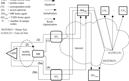
When a MR running NEMO migrates to a foreign network, it replies to any Routing Advertisements it receives from the localAccess Gateway (AG), to receive a new CoA on the visited link (we assume the MR is operating as a mobile router and not as a mobile host). It is this AG that provides network connectivity for the MR and the nodes within it. The MR then sends a Binding Update (BU) message to its HAMR, informing it of its
change of CoA (See Figure2.1step (1)). The HAMRupdates its HoA-to-CoA cache for that
MR and replies with a Binding Acknowledgement (BA). This act sets up and maintains the bi-directional tunnel between them.
Packets meant for the MR are received by the HAMR, which then uses IP-in-IP
encapsula-tion to forward the packets to the MR at its latest CoA. All egress packets from the mobile network, sent from each VMN to its CN, must follow the same return path through the MR-HAMRtunnel first before proceeding to its own respective HAV MN(s) (See Figure2.1
step (6)).
A mobile host has its own Home Address (HoAV MN), which is always returned when a
DNS lookup is performed for that mobile host. When this host becomes a VMN and joins a NEMO mobile network, it first must receive its new CoA (Figure2.1step (2)). It then updates its HAV MN with its CoA by sending a Binding Update (BU)message (See
Figure2.1step (3)). The HAV MN responds with a Binding Acknowledgement (BA). If the
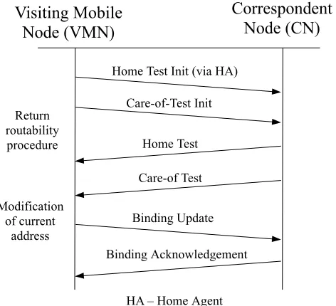
VMN is communicating with any MIPv6-aware CNs (and they are mobility-aware), it will execute a return routability test (RRT) (Figure2.1step (5a)) and subsequently update its CNs with its new CoA, via a BU/BA exchange (Figure2.1step (5b)).
Upon receiving its CoA, a VMN running MobileIPv6 maintains its own bi-directional tunnel between itself and its own HAV MN. Operationally, the VMN-to-HAV MN tunnel
exists within the MR-to-HAMR tunnel. Mobility of the MR and VMN is hidden as all
traffic eventually is sent to/from their respective HAV MNs.
If the MR changes location, it will again negotiate and receive its new CoA and update its HAMRwith its new location (Figure2.1step (4)). The HAMRthen updates its Binding
Cache and the bi-directional tunnel is maintained as it forwards MR packets to the new location.
As for the VMN within the mobile network, it will be unaware of its own mobility as the MR ensures that address on its ingress interface remain unchanged. The mobility of the MR only affects its egress interface. As a result, the VMN will not execute any handovers with its HAV MN or its CNs (if any).
2.2.2 ILNP
The Identifier Locator Network Protocol (ILNPv6) [28] is an experimental extension to IPv6. The termIdentifier-Locator Network Protocol for IPv6 (ILNPv6)is used, as it can be engineered as enhancements to IPv6 [28,51–53]. It splits the IP address into two parts,
theIdentifierand theLocator. TheIdentifier is used for end nodes through the transport
Figure 2.1: The phases of initialisation and handover for a VMN (running Mobile IPv6) and MR (running NEMO). Step (1) shows the MR updating its HAMR via AG1. Step
(2) shows a VMN arriving at the mobile network and registering an IP address gained from the MR. Step (3) shows the VMN updating its own HAV MN. Step (4) shows the MR
moving and conducting a handover by informing its HAV MN of its new CoA. Step (5a)
[image:40.595.93.504.79.338.2]shows the VMN executing a RRT with its CNs. Step (5b) shows the VMN updating its CNs with a new CoA.
Figure 2.2: 2 packets, total of 288 bytes
not a new concept and has been brought up before in [43], [54], [55], [56], [57] and [34].
With regards to the network layer, ILNP maintains additional session cache that holds all
theIdentifierandLocatormappings. Only theIdentifieris exchanged between the network
21
Figure 2.3: 4 packets, total of 560 bytes
[image:41.595.181.417.72.287.2]Figure 2.4: 1 packets, total of 96 bytes
Figure 2.5: 2 packets, total of 208 bytes
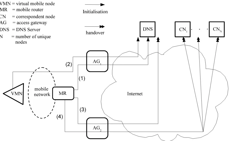
the core routers and routing protocols do not have to change. Nodes that are attached to the mobile network have DNSLPrecords that point to a common DNSLrecord covering the entire mobile (sub-)network. The commonL record would be updated by the MR
whenever its uplink moves to a different layer-3 IPv6 network.
ILNP Operation
Let us assume that the mobile network has an external link with Locator L1 at access
router AG1. This will be held in a DNSLrecord pointed to by a DNSLPrecords for each
host in the mobile network (Figure2.6 step (1)). Within the mobile network, localised addressing is used through Locator rewriting in ILNPv6. That is, a local (private) Locator value,LL, is used by all nodes in the mobile network, and for all egress packets, the MR
rewritesLLtoL1, and performs the complimentary operation for ingress packets, i.e. this
is the ILNPv6 equivalent of NAT, but unlike IP, does not violate end-to-end state and is completely transparent to all ILNPv6 nodes [52]. So,Initialisation for a VMN occurs through a VMN receiving Router Advertisements containing information aboutLL and
theLrecord name for the mobile network, updating itsLPrecord to point to theLrecord of the network (Figure2.6step (2) and Figure2.7).
Now, let us assume aHandoveris triggered for the link currently usingL1. A signal is
de-tected in the new cell and a new Locator value,L2,is attained from the Access Gateway
(AG2). This can be done through normal IPv6 discovery mechanisms, as Locator values
are identical to IPv6 network prefixes. We will assume that the radio cells providing cov-erage, L1 and L2 overlap. Then, the MR updates the DNS Lrecord (currently holding
valueL1) to L2 (for new sessions) (Figure2.6 step (3) and Figure2.8). It then starts
up-dating the state of existing sessions using valueL1to using value L2, by issuingLocator
Update (LU)messages (synonymous to Binding Update message in IPv6) for
correspond-ents usingL1 (Figure2.6step (4) and Figure2.9). It then transitions sessions fromL1 to
L2 using Locator rewriting. When no more packets arrive from remote locations using
L1 within a given time period (i.e. all sessions have transitioned to L2), the connection
is considered to have completed handover. This is asoft handover at the ILNPv6 layer, something that is not currently defined for IPv6 or NEMO. Note that the MR is provid-ing this capability efficiently for the whole mobile network. Note also that durprovid-ing this time, it would also be possible to have another MR and have the whole mobile network multi-homed [52].
It is also possible to use ILNPv6 for normal handover, simply by switching toL2as soon
as possible. Any packets in flight addressed to L1 may be lost, but can be recovered
through the retransmission capability in TCP, for example, albeit this would be ineffi-cient, as it may invoke the congestion control behaviour of TCP as TCP ACKs are lost or delayed.
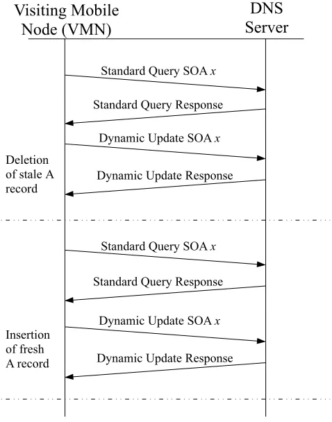
ILNP and DNS
23
Figure 2.6: This figure shows the 2 phases ofInitialisationandHandoverfor a VMN and MR for ILNPv6. Step (1) shows the MR arriving at a new location, receiving an address from AG1and updating its DNS L record with its latest location. Step (2) shows a VMN
arriving at the mobile network, receiving a new (local) Locator and name of the L record for the network, then updating its DNS LP record. Step (3) shows the MR moving to a new location, receiving a new Locator from AG2, and updating its DNS L record with
this new location. Step (4) shows the MR updating all existing sessions between its VMNs and their CNs.
communication with a network host, and uses the DNS name as the invariant, rather than the IP address. This use of a FQDN is consistent with the recommendations for use of names in RFC 1958 [64].
DNS utilises 3 records, they areA(IP address of a domain,32bit),AAAA (IP address of a domain, 128bit) andPTR(domain name to IP address, used for reverse lookup). ILNP
adds an additional 4 new resource records, theI,L,PTRI andPTRL. TheIandLrecords are theIdentifierandLocatorrecords associated with a domain name. ThePTRLrecord is used to name the authoritative DNS server for a givenLocator. ThePTRIrecord is used
to find the domain name for a givenIdentifierin the context of a specific subnetwork ( Loc-ator). Keeping the records forLocatorandIdentifierseparate is more efficient as different hosts will have different levels of mobility. It also makes it easier to assign longer Time To Live (TTL) to records that are more likely to be static. Security is provided by the existing DNS Security specification [65]. Dynamic DNS Updates can be provided by the existing Secure Dynamic DNS Update specifications [66]
In ILNPv6, the mobile network ‘site’ uses private addressinginternally (to the site net-work) and the network’s Mobile Router (MR) rewrites the Locator values of nodes within the site as packets transit that MR. (Note that Locator re-writing does not affect end-system state, as only the Identifier is used by the Transport layer.)
loca-Figure 2.7: 8 packets, total of 1362 bytes
tion update to propagate within DNS in a timely manner; and (iii) that DNS is insecure. However, we take the position that DNS can not only be used to enable host/network mobility, but that it will be extremely capable of doing so:
1. DNS is robust, as lookups and updates are distributed across administratively-delegated, replicated DNS servers [60]. Use of DNS for mobility is as secure as regular DNS, since Secure Dynamic DNS Update [66] is standardised and widely implemented [53].
2. Traffic caused by mobility will be relatively small, as DNS today deals with a load where close to 50% of DNS traffic is caused by misconfigurations, aggressive re-transmissions and poor caching [67].
3. Current implementations of DNS are suitable for use in mobility solutions that re-quire DNS updates at rates as frequent as once per second [68]. Experimental res-ults from [69] show that BIND implementations of DNS with dynamic update can support mobility solutions.
[image:44.595.180.419.72.376.2]25
[image:45.595.180.418.72.380.2]Figure 2.8: 8 packets, total of 1362 bytes
Figure 2.9: 2 packets, total of 144 bytes
So, there are strong indications from previous work to suggest that DNS would be suit-able for supporting mobility.
IPv6 Enhancements
The IPv6 packet header and the ILNPv6 packet header are deliberately made similar. Es-sentially, in ILNPv6, the IPv6 address is broken into two separate components, a Locator (L) and an Identifier (I). Significantly, the IPv6Interface Identifieris replaced by an ILNPv6
Node Identifier(I), with slightly different semantics. TheNaming Approachrecognises
names an IP (sub-)network: this is used only in routing, and not by the upper layers (e.g. not used by TCP or UDP). In practise today, the L value in ILNPv6 packets is exactly the same as the top 64 bits of the IPv6 address, and includes the routing information (see Figure2.10). TheIdentifier is only used for node identity (e.g. for TCP or UDP session state).
The idea of anIdentifier/Locatorsplit is not new, but the ILNP particular approach is new
and is specified in more detail than preceding proposals [55,71,72]. ILNPv6 supports the recommendations of RFC 1958 [64], that applications should use fully-qualified domain names (FQDNs), wherever possible. A summary of the difference between the use of names in IP (v4 and v6) and the use in ILNP is given in Table2.2.
Protocol layer ILNP IP
Application FQDN FQDN, IP address Transport Identifier,I + port no. IP address + port no.
Network Locator,L IP address
Link MAC address MAC address
Table 2.2: Use of names in ILNP and IP.
The Locator (L) is an unsigned 64-bit value carried in the upper portion of the IPv6 ad-dress and is equivalent to an IPv6 adad-dress prefix (see Figure2.10). The (Node) Identifier (I) is an unsigned 64-bit value carried in the lower portion of the IPv6 address. The I value names a (virtual) node itself, rather than the network interface of a node. An end-system may use multiple I values and multiple L values simultaneously. For the duration of a given ILNP session, its I value should remain constant. For practical reasons, the I value is normally formed from one of the MAC addresses associated with the node. This is represented in the IEEE’s EUI-64 syntax, and is very likely to be globally unique as well. This usage is consistent with the IPv6 Addressing Architecture [73]. Strictly, the I value must be unique only within the scope of the L value with which it is used. However, for practical purposes, having an I value that is likely to be globally unique is very useful, and allows us to dispense with IPv6 Duplicate Address Detection (DAD), which in turn greatly reduces the time required for a node to execute a location change.
IPv6:
| 3 | 45 bits | 16 bits | 64 bits |
+---+---+---+---+ |001|global routing prefix| subnet ID | Interface Identifier | +---+---+---+---+
ILNPv6:
| 64 bits | 64 bits |
+---+---+---+---+
| Locator | Node Identifier |
+---+---+---+---+
Figure 2.10: IPv6 address format (from RFC 3587 [74]) as used in ILNPv6: Locator values are IPv6 routing prefixes.
27
(ILNPv6 Locator) is the same as an IPv6 routing prefix, ILNPv6 packets can travel across existing deployed IPv6 backbones. Only the host’s IPv6 stack has to be enhanced to enable ILNPv6 on that host (i.e. to deal with Node Identifier values). ILNPv6 Neighbour Discovery (ND) still uses the full 128-bits of the combined I:L value. So IPv6 ND can also be used without change.
ILNP Security Considerations
In IPsec [75] today, the IPsec Security Associations (SAs) are bound to full IP addresses at the local and remote sites as a form of end-system identity. So, IPsec requires that the IP addresses at each end-point of the communication remain fixed. For mobility (as well as use of localised addressing and multi-homing), this may not remain true, and so IPsec has had to be modified, retrospectively, in order to cope with these functions.
With ILNP, however, IPsec SAs are bound only to the Identifier, never to the Locator. This makes it easy for the IPsec Security Association – and the related secure communications channel – to remain operational even if the end-points move.
For DNS, the existing Secure Dynamic DNS Update standard [66] permits a mobile node to update itsL records when the node moves. Widely used systems, such as Microsoft Windows or the BIND software used with UNIX, already include support for Secure Dynamic DNS Update [76].
So, ILNPv6 simply uses existing security standards for enabling mobile networks, and does not introduce any new security risks compared to IPv6.
Mobile Network Operation
In ILNPv6, the mobile network ‘site’ uses private addressinginternally (to the site net-work) and the network’s Mobile Router (MR) rewrites the Locator values of nodes within the site as packets transit that MR. (Note that Locator re-writing does not affect end-system state, as only the Identifier is used by the Transport layer.)
Nodes that are attached to the mobile network have DNSLPrecords that point to a com-mon DNS L record covering the entire mobile (sub-)network. The common L record
would be updated by the MR whenever its uplink moves to a different layer-3 IPv6 net-work.
Let us assume that the mobile network has an external link with Locator L1 at access
router AG1. This will be held in a DNSLrecord pointed to by a DNSLPrecords for each
host in the mobile network (Figure2.6 step (1)). Within the mobile network, localised addressing is used through Locator rewriting in ILNPv6. That is, a local (private) Locator value,LL, is used by all nodes in the mobile network, and for all egress packets, the MR
rewritesLLtoL1, and performs the complimentary operation for ingress packets, i.e. this
is the ILNPv6 equivalent of NAT, but unlike IP, does not violate end-to-end state and is completely transparent to all ILNPv6 nodes [52]. So, Initialisation for a VMN occurs through the processing of inbound Router Advertisements containing information about
LLand theLrecord name for the mobile network. The VMN then updates itsLPrecord
to point to theLrecord of the network (Figure2.6step (2) and Figure2.7).
Now, let us assume a handover is triggered for the link currently using L1. A signal is


![Figure 3.10: Bandwidth overhead per train [Kb/s], when CN=2, 20% Passenger MobilityRatio](https://thumb-us.123doks.com/thumbv2/123dok_us/8699771.381239/63.595.89.509.79.371/figure-bandwidth-overhead-train-kb-cn-passenger-mobilityratio.webp)
