Calhoun: The NPS Institutional Archive
Theses and Dissertations Thesis Collection
2014-09
Designing a machinery control system (MCS)
security testbed
Desso, Nathan H.
Monterey, California: Naval Postgraduate School
NAVAL
POSTGRADUATE
SCHOOL
MONTEREY, CALIFORNIA
THESIS
Approved for public release; distribution is unlimited DESIGNING A MACHINERY CONTROL SYSTEM (MCS)
SECURITY TESTBED
by
Nathan H. Desso September 2014
Thesis Advisor: Thuy D. Nguyen
REPORT DOCUMENTATION PAGE Form Approved OMB No. 0704-0188 Public reporting burden for this collection of information is estimated to average 1 hour per response, including the time for reviewing instruction, searching existing data sources, gathering and maintaining the data needed, and completing and reviewing the collection of information. Send comments regarding this burden estimate or any other aspect of this collection of information, including suggestions for reducing this burden, to Washington headquarters Services, Directorate for Information Operations and Reports, 1215 Jefferson Davis Highway, Suite 1204, Arlington, VA 22202-4302, and to the Office of Management and Budget, Paperwork Reduction Project (0704-0188) Washington DC 20503.
1. AGENCY USE ONLY (Leave blank) 2. REPORT DATE September 2014
3. REPORT TYPE AND DATES COVERED Master’s Thesis
4. TITLE AND SUBTITLE
DESIGNING A MACHINERY CONTROL SYSTEM (MCS) SECURITY TESTBED
5. FUNDING NUMBERS
6. AUTHOR(S) Nathan H. Desso
7. PERFORMING ORGANIZATION NAME(S) AND ADDRESS(ES) Naval Postgraduate School
Monterey, CA 93943-5000
8. PERFORMING ORGANIZATION REPORT NUMBER
9. SPONSORING /MONITORING AGENCY NAME(S) AND ADDRESS(ES) N/A
10. SPONSORING/MONITORING AGENCY REPORT NUMBER
11. SUPPLEMENTARY NOTES The views expressed in this thesis are those of the author and do not reflect the official policy or position of the Department of Defense or the U.S. government. IRB protocol number ____N/A____.
12a. DISTRIBUTION / AVAILABILITY STATEMENT Approved for public release; distribution is unlimited
12b. DISTRIBUTION CODE A
13. ABSTRACT (maximum 200 words)
Industrial control systems (ICS) face daily cyber security threats, can have a significant impact to the security of our nation, and present a difficult challenge to defend. Critical infrastructures, including military systems like the machinery control systems (MCS) found onboard modern U.S. warships, are affected because of their use of commercial automation solutions. The increase of automated control systems within the U.S. Navy saves in manpower costs but increases the need for cyber security research and defense. Research is needed to assess and contribute solutions to ICS security problems.
This thesis describes the MCS security testbed, which supports research in the security of shipboard machinery control systems. The testbed has been conceptualized, designed and implemented with the vision of supporting research and experimentation on the defense of ICS and MCS systems. The testbed provides the ability to analyze vulnerabilities, test defenses and replicate attacks on authentic physical industrial control equipment. The MCS security testbed is a tool that may help counter cyber security threats facing the defense industrial base today. Future solutions to attacks on control systems in the nation’s critical infrastructure begin with experimentation using authentic test environments.
14. SUBJECT TERMS cyber security, critical infrastructure, supervisory control and data acquisition,industrial control system, machinery control system, programmable logic controller, security testbed
15. NUMBER OF PAGES 183 16. PRICE CODE 17. SECURITY CLASSIFICATION OF REPORT Unclassified 18. SECURITY CLASSIFICATION OF THIS PAGE Unclassified 19. SECURITY CLASSIFICATION OF ABSTRACT Unclassified 20. LIMITATION OF ABSTRACT UU
NSN 7540-01-280-5500 Standard Form 298 (Rev. 2-89)
Approved for public release; distribution is unlimited
DESIGNING A MACHINERY CONTROL SYSTEM (MCS) SECURITY TESTBED
Nathan H. Desso
Lieutenant, United States Navy B.A., The Citadel Military College, 2008
Submitted in partial fulfillment of the requirements for the degree of
MASTER OF SCIENCE IN COMPUTER SCIENCE
from the
NAVAL POSTGRADUATE SCHOOL September 2014
Author: Nathan H. Desso
Approved by: Thuy D. Nguyen
Thesis Advisor
Mark Gondree Thesis Co-Advisor
Peter J. Denning
ABSTRACT
Industrial control systems (ICS) face daily cyber security threats, can have a significant impact to the security of our nation, and present a difficult challenge to defend. Critical infrastructures, including military systems like the machinery control systems (MCS) found onboard modern U.S. warships, are affected because of their use of commercial automation solutions. The increase of automated control systems within the U.S. Navy saves in manpower costs but increases the need for cyber security research and defense. Research is needed to assess and contribute solutions to ICS security problems.
This thesis describes the MCS security testbed, which supports research in the security of shipboard machinery control systems. The testbed has been conceptualized, designed and implemented with the vision of supporting research and experimentation on the defense of ICS and MCS systems. The testbed provides the ability to analyze vulnerabilities, test defenses and replicate attacks on authentic physical industrial control equipment. The MCS security testbed is a tool that may help counter cyber security threats facing the defense industrial base today. Future solutions to attacks on control systems in the nation’s critical infrastructure begin with experimentation using authentic test environments.
TABLE OF CONTENTS
I. INTRODUCTION...1
A. MOTIVATION ...1
B. THESIS OVERVIEW ...2
II. BACKGROUND ...3
III. TESTBED DESIGN ...9
A. ANALOG FLUID TANK LAB ...10
B. DIGITAL I/O LAB ...12
C. PROGRAMMABLE LOGIC CONTROLLER ...13
D. HUMAN MACHINE INTERFACE ...14
E. DEVELOPMENT ENVIRONMENT ...14
F. OPERATORS AND THEIR ROLES ...15
1. HMI Operator ...15
2. HMI-Override Station Operator ...15
3. Fluid Level Simulation Dial Operator ...15
IV. ANALOG FLUID TANK LAB ...17
A. CONCEPT OF OPERATIONS ...17
1. AFTL Human Machine Interface...17
2. PLC Rack ...18
3. HMI Override Station ...18
4. Automatic Mode of Operation ...18
5. Manual Mode of Operation...19
B. DESIGN ...19
1. Controlling and Monitoring the Fill Pump ...19
2. Controlling and Monitoring the Drain Valve ...20
3. Reporting the Status of the Tank Fluid Level ...20
4. Dynamically Monitor the Fluid Level of the Tank ...20
5. Controlling the Fill Pump and Drain Valve in Automatic Mode ..21
6. System Control and Indications ...21
7. Targeted Fluid Level Adjustment and Alarm Indications ...22
8. Monitoring Ethernet Traffic Within the Supervisory Segment ....23
C. IMPLEMENTATION ...24
1. Engineering Workstation and HMI ...24
2. AFTL PLC ...25
3. HOS ...28
V. DIGITAL I/O LAB ...33
A. CONCEPT OF OPERATIONS ...33
1. Digital I/O Human Machine Interface ...33
2. Programmable Logic Controller ...33
3. Robot Arm ...34
B. DESIGN ...34
1. Controlling the Robot Arm ...35
2. Moving Objects Using the Robot Arm ...35
3. Dynamically Displaying the Status of the Proximity Sensors ...36
4. Displaying the State of the Robot Arm and Commands Issued ....36
5. Displaying Indications When an Error has Occurred...36
C. IMPLEMENTATION ...37
1. Engineering Workstation and HMI ...37
2. Digital I/O PLC ...39
3. Robot Arm and Proximity Sensors ...40
VI. TESTING ...43
A. FUNCTIONAL TESTING PLAN ...43
B. EXCEPTION TESTING PLAN ...47
C. TESTING PROCEDURE ...49
VII. CONCLUSION ...51
APPENDIX A. TESTBED WIRING SCHEMATIC ...53
APPENDIX B. AFTL WIRING CONNECTION DIAGRAM ...55
APPENDIX C. DIOL WIRING CONNECTION DIAGRAM ...57
APPENDIX D. AFTL TESTBED STATE DIAGRAM ...59
APPENDIX E. DIGITAL I/O LAB STATE DIAGRAM ...65
APPENDIX F TESTING PROCEDURES ...71
LIST OF REFERENCES ...161
LIST OF FIGURES
Figure 1. Basic PLC Group used in MCS systems, from [14] ...5
Figure 2. MCM-1 digital MCS system, from [14] ...6
Figure 3. Testbed overview diagram ...10
Figure 4. Allen Bradley 1746-A4 (4-slot I/O chassis) with power supply ...14
Figure 5. HMI Override Station front panel including FLSD ...23
Figure 6. AFTL HMI screenshot (automatic mode, normal fluid level) ...24
Figure 7. Testbed network design ...25
Figure 8. Sequence of indications (1–3) during power-up of the PLC ...26
Figure 9. HMI pump status indicator and controls ...29
Figure 10. PLC I/O modules their slot locations 0–3 (left to right) ...30
Figure 11. HMI override station controls and indications...31
Figure 12. DIOL HMI screenshot ...37
LIST OF TABLES
Table 1. AFTL functional requirements ...11
Table 2. Digital I/O lab functional requirements ...12
Table 3. Functional requirements...43
LIST OF ACRONYMS AND ABBREVIATIONS
AB Allen Bradley
AFTL analog fluid tank lab
CCS central control station
CONOPS concept of operations
COTS commercial of the shelf
CPU central processing unit
CVN nuclear aircraft carrier
DCS distributed control system
DDG guided missile destroyer
DIOL digital input output lab
FLSD fluid level simulator dial
FLT fault
GUI graphical user interface
HMI human machine interface
HOS human machine interface override station
ISCS integrated ship control system
I/O input and output
IDE integrated development environment
IEC international electrotechnical commission
LAN local area network
LED light emitting diode
LHD landing helicopter dock amphibious ship
LVL level
MCM mine countermeasure ship
MCS machinery control systems
NIC network interface card
NPS Naval Postgraduate School
OS operating system
SC MCS smart carrier machinery control system
SCADA supervisory control and data acquisition
SPST single pole single throw
TF functional test
TE exception test
VDC volts direct current
VLV valve
ACKNOWLEDGMENTS
I would like to express thanks to my wife and children for their patience and the sometimes-needed distraction that provided me with the motivation I so desperately needed through this entire thesis process.
I would also like to thank my parents, Hoyt and Maryann Desso, for always telling me that I can do anything that I put my mind to. The encouragement, structure and basic core values you gave me have always guided me to success.
I would like to thank Prof. Mark Gondree and Prof. Thuy Nguyen as my advisory team. Thank you for your patience, assistance and dedication to seeing me through this process.
Finally, I would like to thank God for his hand in molding me into the person that I am today. I give thanks to Him for the many blessings that He has bestowed upon me.
I.
INTRODUCTION
A. MOTIVATION
On a daily basis, the cyber security operations community identifies vulnerabilities in Supervisory Control and Data Acquisition (SCADA) systems, industrial control systems (ICS’s) and machinery control systems (MCS’s). Today’s modern U.S. warships use control systems that are similar to, or the same as, those found in the civilian industry. Critical industrial control systems like those found in electrical networks, MCS’s onboard warships, water storage facilities and oil refineries constantly require patches or monitoring for newly discovered security flaws. The concern over vulnerabilities in SCADA systems is due to the equipment they control and their impact, as an unprotected security flaw can lead to loss of a critical capability, loss of life or limb, and a threat to national security.
According to DHS’s 2013 ICS-CERT year-in-review, there was an average of one ICS incident every 34 hours, for a total of 257 incidents reported in the United States [1]. In July 2014, ICS customers seeking a PLC software update inadvertently downloaded a maliciously planted Trojan, dubbed Havex. The Havex Trojan scans a widely used PLC standard called open protocol communications (OPC) and is believed to gather information about vulnerabilities in the target system, as a way to test code before a larger attack. The Havex Trojan affected a German manufacturing company, a Belgium PLC VPN software company and a Swiss company that produces industrial cameras [2], [3]. Another cyber attack called “Careto” or “The Mask” was a widespread espionage malware attack targeted at government agencies, energy, oil and gas companies and research organizations. The malware intercepts all communication channels and collects vital information from the victim’s machine, to facilitate the theft of private information from ICS’s [4]. Relatedly, recent vulnerabilities discovered amongst maritime ships using global positioning systems (GPS), automatic identification systems (AIS), and electronic chart display and information system (ECDIS) have uncovered serious flaws in security [5]. Flaws in maritime systems give hackers the ability to change the direction of the ship
using false GPS data, manipulate chart data and shut down the ships ability to communicate with ports or other ships using AIS [5]. The U.S. Navy uses all of these systems and is exploring ways to integrate ICS’s with navigation systems like ECDIS and AIS in a push toward autonomous warships [6]. In the U.S. Department of Defense (DOD) the criticality of ICS and MCS systems are directly linked to the defense of the nation, and in the case of the Navy, directly linked to warships and national assets.
Learning the vulnerabilities of the ICS and MCS systems and having the ability to test for possible defenses using an authentic testbed is valuable to cyber security. In particular, this line of research is in direct support of Presidential Policy Directive PPD-21 and Presidential Decision Directive 63 to secure critical infrastructure from cyber attack [7], [8]. The ability to test using actual industry standard equipment in real time will provide valuable insight into identifying vulnerabilities applicable to both the military and civilian domains. A testbed has been used in other colleges and universities to educate researchers on SCADA [9], [10], [11], but limited work has been done targeting U.S. Navy or military applications. The testbed described in this thesis is built to assess system communication vulnerabilities and allow for simulated attacks on authentic physical systems without damaging expensive equipment or placing personnel at risk. The testbed provides a testing environment for both control and monitoring of machinery systems similar to the military and civilian industry.
B. THESIS OVERVIEW
In Chapter I, we provide motivation for the MCS security testbed. In Chapter II, we discuss the background of ICS and MCS in the U.S. Navy and the major components that make up an MCS. In Chapter III, we discuss the design of the MCS security testbed. In Chapter IV, we describe the analog fluid tank lab (AFTL) concept of operations (CONOPS), design, implementation and functional requirements. In Chapter V, we describe the digital I/O lab (DIOL) CONOPS, design, implementation and functional requirements. In Chapter VI, we discuss the testing plan designed to support the testbed requirements. In Chapter VII, we conclude.
II.
BACKGROUND
Control systems in general are collections of hardware, software, communication networks (or media) that are used to monitor and control processes, services, or commodities [12]. There are two primary types of control systems. Distributed Control Systems (DCS) typically are used within a single processing or generating plant or over a small geographic area. Supervisory Control and Data Acquisition (SCADA) systems typically are used for large, geographically dispersed distribution operations. For example a utility company may use a DCS to generate power and a SCADA system (or network) to distribute the control and monitoring of it [13]. In the U.S. Navy a machinery control system (MCS) is a type of DCS used to remotely actuate, control and monitor machinery equipment like engines, electrical plants and auxiliary systems [14]. The U.S. Navy MCS combines many systems into one network to both operate and monitor the entire engineering plant utilizing different communication protocols but does not span a large geographical area. Because of the small geographical area covered, by definition the MCS’s of the U.S. Navy are not SCADA systems. However, most recently amongst the cyber security and naval systems engineering personnel the term SCADA has become synonymous with both DCS and MCS type systems. Since the naval MCS systems use the exact commercial off the shelf (COTS) components as found in SCADA systems, the term SCADA MCS will be used in the remainder of this thesis to mean “the network of digital and analog commercial components found aboard naval ships that are monitoring and controlling naval machinery systems” [6], [14].
Machinery control systems have evolved significantly in both the military and civilian applications from the direct wire and gauge days of the past to automated digital controls and displays of today. Machinery controls have moved from hardware-based logic to software-based logic where lights and pushbuttons are replaced by processors, graphical user interfaces and keyboards [14]. Despite the advantages, the U.S. Navy initially showed reluctance to move from hardware centric systems to software centric systems for fear of relinquishing control to automated systems. However, the cost savings in personnel associated with adopting a software centric COTS system proved to be
enough to move forward with the modernization and upgrade of current and future shipboard MCS systems [14]. The U.S Navy currently utilizes software PLC centric machinery control systems to operate all variations of systems on multiple ships from mine countermeasure ships to aircraft carriers. Historically, on older systems the major components include control consoles or panels, hard-wired analog interfaces to sensors and equipment, and a network of hardware to remotely control each major component in the engineering system. Today the systems have evolved to the digital and analog computer centric networked systems found on modern aircraft carriers (CVN), guided missile destroyers (DDG) and large amphibious platforms like the USS Makin Island
(LHD-8). It is these systems that have reduced manpower requirements, increased information flow and automated many engineering processes that present challenges in security and require a navy testbed for experimentation [14].
MCS systems of today are complex networks that are comprised of engineering workstations, human machine interfaces (HMI), PLC’s and a connected network centered on a fiber optic or Ethernet backbone (see Figure 1). The engineering workstation is a computer workstation (usually Windows based) that a technician can use to load software, monitor the PLC’s health and adjust or configure the support network. PLC’s are processor and I/O units connected to the MCS network that operate on logic software and directly monitor and control equipment. The PLC racks are comprised of central processing units (CPU) and input output (I/O) modules that share information via a common internal bus as well as interface with the machinery plant directly. HMI’s are graphical user interfaces that allow the operator to monitor and control systems remotely through the network. The network that connects these components utilizes Ethernet or fiber optic cables interconnecting hubs that will direct and route information and controls for various systems.
Figure 1. Basic PLC Group used in MCS systems, from [14]
In the U.S. Navy, the progression from the old hardware systems to the current software based systems began with the DDG-51 class ships and continues through the future CVN-78 systems. The DDG-51 system was the first to be outfitted with all digital MCS systems. The advantages offered by the DDG-51 system over control systems of the past were easy setpoint adjustment and quicker information flow to the operator [14]. The next naval system to improve on MCS design was the MCM-1 system that replaced the Integrated Ship Control System (ISCS) with a COTS system that reduced crew workload, provided state of the art commercial control systems with 24-hour support, provided on-board crew training and interfaced with the original ISCS hardware seamlessly. The MCM-1 class MCS was the first class-wide modern control system [14]. The MCM-1 system consisted of two PLC cabinets (one with a processor with logic and an analog I/O module and the other with a digital I/O module) and three generator local control electronic enclosures. The MCM-1 MCS interconnected all the PLC’s using Ethernet
connections to local area network (LAN) hubs that exchanged information while using fiber optic connections as a backbone for redundancy. The PLC’s in the MCM-1 system were the heart of the system and allowed the operator to monitor many systems but only control one at a time. The signal routing for commands and monitoring was initiated from a console or HMI located in the central control station (CCS) or locally in each engine room. The signal from the HMI would be sent to the PLC and output by the PLC would control the equipment as desired. The feedback as to the status of the monitored equipment was received by the PLC and displayed back on the HMI (see Figure 2). The advantages of the system were readily apparent and ready to be adapted to larger platforms like the CVN [14].
Figure 2. MCM-1 digital MCS system, from [14]
The U.S. aircraft carriers (CVN), before 2000, operated all auxiliary systems by hand or using hard-wired remote control and alarm panels operate them. The control systems in use were very labor intense and did not provide much in the way of situational awareness to the operator. The smart carrier machinery control system (SC MCS) was
developed to incorporate the network of controls and information from the currently installed systems into a digital network that can be monitored and controlled remotely [14]. The SC MCS combined systems like fuel, fire main pumps, potable water, bilge and drain (to name a few) into one state of the art MCS system similar to that of the MCM-1 system. However, unlike the MCM-1 system the SC MCS system was the first MCS to use a complete Ethernet LAN (no fiber optic was used) [14]. The system comprised of as that of the MCM-1 system; it had HMI’s, PLC’s with interface directly to machinery and an Ethernet hub backbone. The SC MCS system was innovative for the CVN ships because it works with existing systems and requires less manpower while providing better equipment status. The future CVN’s (starting with CVN-78) will be built from the very beginning with the SC MCS systems in an effort to further incorporate ships systems together [14].
The MCS systems in the U.S. Navy have allowed the improvement of quality information to be readily available while reducing the number of operators and technicians needed. However, the increasing size and capabilities of these MCS networks and their integration into other systems in the future (like the littoral combat ship or LCS) make them increasingly vulnerable to malicious software, hardware or other network attack vectors yet to be discovered [14]. The Navy cyber security professionals are aware of the threats and vulnerabilities facing the SCADA systems used and are constantly working to improve security of these systems. However, there is always a need to perform cyber security testing on MCS systems without impacting real equipment operation or the deployment schedules of national assets like aircraft carriers.
In the civilian sector SCADA network testbeds have been designed and implemented to test threats to various industries and the networks that they utilize with great success. Some systems like that at Mississippi State University (MSU) even utilize working scaled models of the machinery systems they are replicating [10]. The testbeds at MSU use two different communication types between the HMI and PLC and various types of digital and analog control and monitoring I/O signals. The signals used on the MSU testbed are used to simulate storage tanks, water towers, factory conveyors and
smart grid transmission systems and provide multiple research points for the cyber security, systems engineering and electrical engineering domains [10]. Other testbeds like those designed by researchers at UC Berkeley, Carnegie Mellon University and Vanderbilt University are completely emulated networks of virtual components where commercial operating software runs on equivalent hardware while receiving simulated sensor data [9]. The emulation of the testbed components and sensor data is flexible, convenient, and inexpensive but the U.S. Navy requires the ability to test specific manufacturers hardware and software in order to target specific vulnerabilities that may exists only in MCS systems contracted by the U.S. Navy. Despite differences among existing testbeds, the use of a testbed to discover and experiment is very valuable to research and testing both in the military and in the civilian industry.
III.
TESTBED DESIGN
The NPS MCS security testbed designed in this thesis provides a working model that replicates the MCS systems in the fleet today. The testbed utilizes components normally found in commercial MCS systems allowing for realistic cyber security testing and research without concern of damaging expensive equipment or effecting operational readiness of a national asset like a CVN. The NPS MCS testbed is designed to allow experimentation and future research in the areas of SCADA cyber defense and attack in order to improve the security of current implemented systems and possibly provide input into future MCS designs.
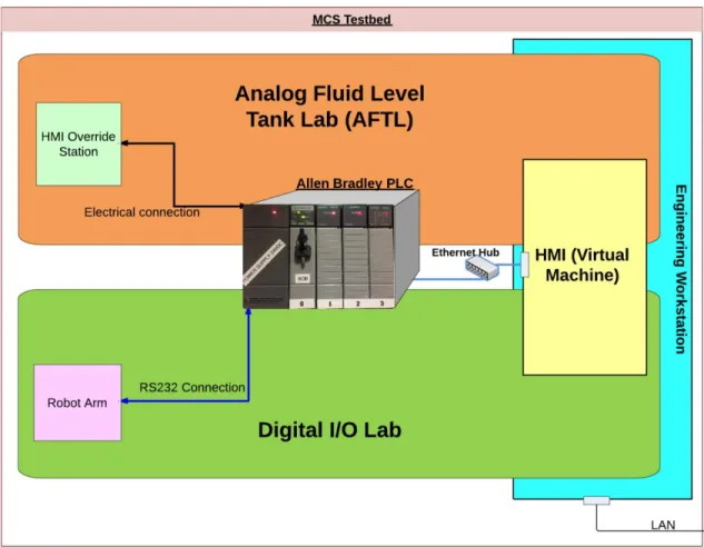
The machinery control system security testbed consists of two test systems: an analog fluid tank lab (AFTL) and a digital I/O lab (DIOL) (see Figure 3). These test systems share a programmable logic controller (PLC) rack, a human machine interface (HMI) system running as a virtual machine, and an engineering workstation used to program the PLC (Table 1). The two test systems allow for future study of vulnerabilities and malicious code in SCADA MCS systems in an offline controlled lab setting. Each test system is described in this chapter.
Figure 3. Testbed overview diagram
A. ANALOG FLUID TANK LAB
The analog fluid tank lab models the fluid and storage tank systems found onboard most U.S. Navy ships and in industry. The AFTL uses analog command and sensor signals to control a pump and drain valve in order to maintain the fluid level in a simulated tank. Most control systems support an HMI-override (HOS) mode of operation where a local operator can take control of the PLC in the event of an emergency. The AFTL also provides the HOS capability.
The following functional requirements are levied on the AFTL (Table 1).
Table 1. AFTL functional requirements
ID Description
R1 The AFTL shall dynamically display the level of the fluid tank to the operator at all stations.
R2 The AFTL shall allow the operator to control the fill pump.
R3 The AFTL shall dynamically display the status of the fill pump. R4 The AFTL shall allow the operator to control the drain valve. R5 The AFTL shall dynamically display the status of the drain valve.
R6 The AFTL shall alert the operator when the tank level is above or below its target level.
R7 The AFTL shall allow the operator to adjust the target level parameter during normal operation.
R8 The AFTL shall provide the ability to operate in fully automatic mode, to control the fill pump and drain valve in order to maintain the fluid level at its target level without operator intervention.
R9 The AFTL shall allow the operator to have exclusive and direct system control in
the event of an emergency.
R10 The AFTL shall communicate the status of the tank fluid level to the control segment using continuous, analog signals.
R11 The AFTL shall provide the ability to monitor Ethernet traffic between the control and supervisory network segments.
B. DIGITAL I/O LAB
The digital I/O lab demonstrates the data flow between the PLC, HMI, and a digital field device—a robot arm. Proximity sensors will sense the location of the object to be moved. The sensors provide feedback to ensure the proper command is issued to the robot arm to move the object. The data transfer from HMI to robot arm is not simply a signal that changes a bit inside the PLC like the AFTL; the DIOL requires a complete, properly sequenced and formatted digital command signal in order to produce the desired output. The DIOL is designed to allow for testing of the command signals from the HMI to the PLC and the robot arm. The DIOL used in this testbed is a re-implementation of earlier work here at NPS by Ward that focuses more on security of a SCADA network from a protocol and theory standpoint and focuses less on design and implementation of a testbed [15,12].
The following functional requirements are levied on the digital I/O lab (Table 2).
Table 2. Digital I/O lab functional requirements
ID Description
R12 The DIOL shall operate a robot arm to move objects as commanded.
R13 The DIOL shall display the status of all proximity sensors. R14 The DIOL shall display the readiness status of the robot arm.
R15 The DIOL shall display all commands sent to the robot arm as they are executed. R16 The DIOL shall indicate when an error has occurred or exceptional condition
exists
R17 The DIOL shall only move objects to proximity sensors that are inactive and shall not move the robot arm when no objects are detected by the proximity sensors.
C. PROGRAMMABLE LOGIC CONTROLLER
The programmable logic controller (PLC) is the heart of an MCS because it is where all sensors and command signals pass through in order to control the field devices. The PLC used in the testbed is a combination of Allen Bradley components. The CPU is an Allen Bradley SLC-5/05 CPU (slot 0) attached to a 1746-A4 4-slot I/O chassis powered by a P1 onboard power supply with three I/O modules: the AB 1746-NIO4V (slot 1), AB 1746-NO4V (slot 2) and AB 1746-IO12DC (slot 3) (see Figure 4). The PLC CPU is connected to the HMI and Engineering Workstation via Ethernet. Sensors and other analog devices are wired to each I/O module using copper wiring (see Appendices A–B). The sensors, I/O controls, LED indicators and power are wired directly to the 1746-NIO4V, 1746-NO4V and 1746-IO12DC I/O modules. The robot arm is connected as part of the DIOL to the CPU module via an RS-232 interface [16], [17], [18].
Figure 4. Allen Bradley 1746-A4 (4-slot I/O chassis) with power supply
D. HUMAN MACHINE INTERFACE
The human machine interface (HMI) is a computer that has the ability to remotely control the PLC and monitor its status. The HMI in the MCS testbed interfaces with the PLC using an Ethernet connection that can be monitored by other computers for testing and experiments. Using the HMI, a tester can inject commands to the PLC, monitor how the data is formatted and sent to the PLC, and observing the output.
E. DEVELOPMENT ENVIRONMENT
The development environment is the computer hardware and software that is used to create the ladder logic program running on the PLC, the HMI graphical interface and network access used to communicate with the PLC. The development environment in the MCS testbed consists of a physical host machine and a guest virtual machine for use as
the HMI; the host machine acts as an engineering workstation where a technician or engineer can make changes or implement updates to the HMI or PLC. The engineering workstation allows testing and experimentation on ladder logic changes, interception or manipulation of firmware loads and traffic capture.
F. OPERATORS AND THEIR ROLES
The MCS testbed requires three operators in order to function properly. Each operator is present at a station that has a specific function in the MCS testbed. The stations each have independent controls and receive or display some type of information about the MCS testbed status. Each operator is a “human in the loop” who will interpret the data displayed or indicated and issue commands accordingly. The operators needed for the MCS are listed in the following paragraphs.
1. HMI Operator
The HMI operator is located at the HMI and can monitor the graphical display of the AFTL or the DIOL. The HMI operator can observe the status of the field devices via the graphical indications as if they were seen at a remote station. Further, the operator can start, stop or command the analog and digital equipment.
2. HMI-Override Station Operator
The HMI override station (HOS) operator is located at the HOS and can monitor the status of the AFTL and manually controls the fill pump and the drain valve. The HOS operator simulates the operator that would use the HOS to control the equipment directly in the event of an emergency. The HOS uses the input signals to prompt the PLC’s ladder logic to act independently of the HMI inputs or any changes that may be influencing the PLC. The HOS operator has as close to manual control of the AFTL as possible.
3. Fluid Level Simulation Dial Operator
The FLS operator is located at the fluid level simulator dial (FLSD) portion of the HOS and can increase or decrease the tank level via a manual dial—the simulation operator can adjust the FLSD, simulating the raising or lowering of the fluid level in the
AFTL “tank.” The level indicated on the dial will be continuously updated and displayed on the HMI. The operator is able to adjust the FLSD for testing or simulation purposes.
IV.
ANALOG FLUID TANK LAB
The Analog Fluid Tank Lab (AFTL) is the component of the MCS testbed that provides a platform to experiment with MCS systems using analog I/O. The AFTL is intended to resemble an authentic cyber-physical system that controls field equipment by monitoring continuous, or analog, I/O signals. The AFTL simulates a tank-level monitoring system, a type of system commonly found in shipboard machinery control systems. An Allen Bradley programmable logic controller (PLC) allows experimentation with various controls and outputs communicated over an Ethernet/IP connection. The AFTL offers the ability to analyze and experiment with the network traffic associated with controlling analog field devices in the testbed.
A. CONCEPT OF OPERATIONS
The AFTL attempts to resemble an authentic tank-level control system, which manipulates a fill pump device and drain value to either empty or fill a tank, affecting the fluid tank level. Functional requirements of the AFTL are listed in Table 1. The AFTL is comprised of four primary components: the HMI machine (supervisory segment), the PLC rack (control segment), the HMI override station, and simulated field devices. The system operates in two basic modes of operation: manual and automatic. We describe each of these in more detail, below.
1. AFTL Human Machine Interface
The HMI system presents a graphical interface of the tank level system, allowing the operator to control and monitor the status of the tank level. The HMI displays the following: the status of the fluid tank level, the fill pump, the drain valve; the current mode of operation; alarms; target level parameters; and the identity of the station (HMI/HOS) currently controlling the system. The fill pump, drain valve and mode of operation can be controlled using the HMI (see Figure 6).
2. PLC Rack
The PLC, as part of the AFTL, is the data engine that continuously serves the HMI by updating the status of all sensors and executing commands as they are received. The PLC CPU constantly cycles through all the status bits stored locally in memory including the FLSD input status and HMI pump and valve commands. The PLC will respond to changes in the state of the active memory bits in accordance with the Ladder Logic program that is stored onboard the PLC. When logic conditions are met to cause an output the PLC will execute those commands by signaling the appropriate I/O module to change the bit at an address controlled by the I/O module. The change in status by that bit will cause all monitoring programs to update. In the case of the AFTL when a command from the HMI to start the pump is received the PLC will refer to the Ladder Logic and change the status of the pump to running. All indicators that are monitoring the pump status will be updated as to its new state. For details on the PLC configuration, see Chapter III.
3. HMI Override Station
The HMI override station (HOS) is a station directly connected to the PLC that provides an alternate point of control, without intervention of the HMI. The HOS provides a set of sensors and actuators to monitor and control the system, manually. In the event the control segment were to malfunction or when local control is desired, the HOS allows an operator to take control from the HMI and force the system into a manual control mode. While in this mode, the local operator controls the system from the HOS. In MCS, a local control station like the HOS is the preferred mechanism for controlling machinery when in emergency scenarios, due to its adjacency to equipment and direct connection to the PLC (see Figure 5).
4. Automatic Mode of Operation
While in the automatic mode of operation, the AFTL operates without operator intervention. In this mode, the PLC monitors sensors and initiates commands to correct the system status when observed to be outside a target state (i.e., by controlling the fill
pump and drain valve). The operator at the HMI cannot control the pump or valve, but can adjust the alarm set points except during an alarm condition.
5. Manual Mode of Operation
The HOS and HMI can each operate the system manually. While in the manual mode of operation, an operator has full control of the fill pump and drain valve from either the HMI or HOS station. When the system has completed the transition from one mode to another mode of operation, the pump and valve commands issued in the exited mode are ignored. While the system is in manual mode, the only commands accepted are those at the station in manual control (HOS or HMI).
B. DESIGN
In this section, we describe each component reflected in the CONOPS and the functionality needed by those components to support the AFTL requirements. The functionality of each component is outlined below, but implementation details are deferred to later in this chapter. The allocation of functional requirements (from Table 1) to each AFTL component is provided below, for traceability.
1. Controlling and Monitoring the Fill Pump
At the HMI, a representation of the pump control and status is presented to the operator via a graphical user interface (GUI). The operator can click to start and stop the pump. The status of the pump is displayed to the GUI, providing feedback that the command was successful.
At the HOS, the pump control is an electrical switch that signals the PLC to change the status of the pump. The pump status is displayed as a light indicator, providing feedback that the command was successful.
2. Controlling and Monitoring the Drain Valve
At the HMI, a graphical representation of the drain valve status and control is displayed to the operator. The operator can place a drain valve in the OPEN or CLOSED position. The status of the valve is displayed to the GUI, providing feedback that the command was successful.
At the HOS, the drain valve control is an electrical switch that signals the PLC to change the status of the drain valve to the OPEN or CLOSED position. The pump status is displayed as a light, providing feedback that the command was successful (see Figure 2).
Requirement traceability: R4, R5
3. Reporting the Status of the Tank Fluid Level
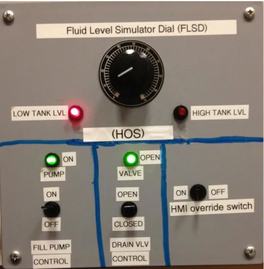
The AFTL requirements do not require devices that hold or manipulate actual fluid resources. Instead, electrical components providing continuous signals are used to implement a notional tank. The fluid level simulator dial (FLSD) is an electrical rheostat located at the HOS that can be manually adjusted to any level between 0 and 100 percent as indicated on the FLSD or 0 and 32700 gallons as displayed by the HMI (see Figure 5).
The FLSD induces electrical signals, acting in the role of a tank equipped with a level sensor. The FLSD state (referred to as “fluid level” in the remainder of this work) is displayed at the HMI graphically, and at the HOS by reading the state of the dial pointer. The FLSD position is an analog input affecting the system state (i.e., level alarms and automatic mode logic (see Figure 5).
Requirement traceability: R10 number headings
4. Dynamically Monitor the Fluid Level of the Tank
At the HOS, the operator can observe the fluid level via a physical needle pointer located on the dial using a 0-100 scale at the FSLD. At the HMI, the fluid level is displayed through an intuitive graphical interface consisting of a representation of a tank along with a numerical display of the gallons of fluid currently in the tank. In normal
operation, when the fluid level is between the low and high alarm target limits, the fluid level is shown in blue. When the fluid level is below the low alarm target level, the fluid will be indicated in red. When the fluid level is above the high alarm target set point, the remainder of the tank graphic will fill with red. During normal operation the actual fluid level in gallons will be displayed next to the tank. The numerical level in gallons will be displayed next to the tank and constantly updated regardless of any alarm condition.
Requirement traceability: R1
5. Controlling the Fill Pump and Drain Valve in Automatic Mode
At the HMI, the operator uses a graphical representation of a switch to place the system in automatic mode. While in this mode, the PLC responds to the low and high level alarm conditions to control the fill pump and drain valve operations and ultimately maintaining the desired fluid level. The FLSD can be adjusted manually to simulate the effect of the tank being filled or drained.
At the HOS, a control for selecting automatic mode does not exist. When the HOS override switch is in the ON position, the HOS has control and the AFTL only operates in manual control mode.
Requirement traceability: R8
6. System Control and Indications
At the HMI, the station in control of the AFTL is displayed via a graphical indicator that displays the status of the system control. By default, control is assigned to the HMI. In the event the HOS has taken control, all HMI operator commands are ignored and the HMI operator will be unable to control the system. A graphical indicator displayed at the HMI will indicate that HMI controls have been overridden. The fill pump, drain valve, alarms, and tank fluid level status will continue to display the state of the system, accurately and continuously.
At the HOS, if the HMI Override switch is placed in the ON position, a signal is sent to the PLC to disable all controls from the HMI. The fill pump motor and drain valve
can be adjusted accordingly. All changes to the system state made at the HOS will continue to be displayed at the HMI accurately and continuously regardless of the station in control.
Requirement traceability: R9
7. Targeted Fluid Level Adjustment and Alarm Indications
At the HMI, the operator can adjust the targeted alarm set points by manually setting the value for the high or low alarm condition in gallons. When the targeted level is reached, a visual alarm will blink and the fluid of the tank will change color indicating that the level of the tank has reached a desired level. The alarm levels can also be used to trigger the system to change states automatically. During automatic operation the target level will be used to signal the starting or stopping of the fill pump or the opening or closing of the drain valve.
The HOS has neither the ability to adjust the targeted fluid level nor the ability to operate in automatic mode.
Figure 5. HMI Override Station front panel including FLSD
8. Monitoring Ethernet Traffic Within the Supervisory Segment
Packet analysis software implemented within the HMI virtual machine will allow a researcher to monitor or sample traffic sent to and from the PLC. Additionally, an Ethernet hub will be used to allow monitoring or sampling of the traffic flow between the HMI and the PLC by another machine for possible injection or exploitation purposes.
Figure 6. AFTL HMI screenshot (automatic mode, normal fluid level)
C. IMPLEMENTATION
Next, we describe the implementation of the AFTL, based on the various system states that the AFTL system can enter and the transitions necessary to arrive at each state. A complete state diagram is provided in Appendix D.
1. Engineering Workstation and HMI
The engineering workstation is a computer running Windows 7 as a host to a VMware virtual machine operating Windows XP SP2 as a guest OS. The host machine has two network interface cards (NIC) that allow the guest OS virtual machine (HMI) to have a direct connection to the PLC through an Ethernet connection and also connect to the campus LAN without affecting the network addressing of the NPS MCS testbed. The HMI is connected exclusively to the PLC through Ethernet on the SLC-5/05 CPU (slot 0).
At the engineering workstation, the operator uses software running on the Windows XP guest VM to implement ladder logic software and to design the HMI
program. The ladder logic is uploaded to the PLC using Rockwell Automation’s RSlogix
500 programming IDE software. The HMI program is written using Rockwell
Automation’s RSView32 Works development environment and Microsoft Visual Basic [19]. During run-time, the HMI program runs under the RSView32 Runtime environment, which restricts changes to the layout and functionality of the HMI program. The program uses tags to store and display the sensor data and equipment status of the AFTL.
The PLC, the engineering workstation and the HMI are configured with IP static addresses but only the HMI and PLC share a subnet (see Figure 7).
Figure 7. Testbed network design
2. AFTL PLC
The PLC program (written in ladder logic) receives HMI and HOS commands, monitors inputs for changes and outputs signals when conditions are met internally. The status of all sensors are continuously updated by the PLC CPU cycle and displayed accordingly.
The PLC must be powered up prior to HMI operation. The PLC is working properly when the following conditions are met: 1) the PLC has 120VAC power, 2) the red power LED located on the power supply is lit, and 3) the “FLT” flashes on briefly followed by all the LEDs and then they are all quickly extinguished (see Figure 8). After a successful power-up sequence, the “RUN” and “ENET” lights should be lit and the PLC programming key must be in the “REM” position (see Figure 10). The power-up sequence fails when the indications described are not met or if the “FLT” light is lit constantly [20].
Figure 8. Sequence of indications (1–3) during power-up of the PLC
Once fully powered up, the PLC receives commands from the HMI and HOS as specified by the operator, and retrieves all data from each I/O module via the common
data bus between modules. The commands from the HMI are sent via the Ethernet connection to the CPU module. Commands are issued by changing a predetermined status bit inside the PLC memory. The status bits are monitored and updated each cycle of the PLC CPU. The CPU will update the status of sensors and act on commands from the HMI and outputs at the HOS based upon the ladder logic program stored onboard the PLC.
The ladder logic program is a graphical programing language that acts as a circuit where the input to the ladder rung affects some output. Ladder logic is commonly used in PLC’s in accordance with the IEC 61131-3 [21]. The ladder logic program used in this testbed is loaded onto the internal memory of the CPU module via the Ethernet connection between the PLC CPU module and the Engineering Workstation using the RSLogix 500 IDE software [20], [22]. During the upload process the PLC will no longer monitor or update the status of any sensors. Once the PLC is placed in RUN mode, the uploaded ladder logic program will start executing.
The ladder logic program code that controls the AFTL consists of a main program and four other sub-programs. Each sub-program is enabled or called by the main program and act as methods supporting the various states of the AFTL. The main program is used to enable the four sub-programs: automatic mode, manual mode, HMI control, or HOS control. The compartmentalization into isolated sub programs provides exclusive control of the AFTL in each state and prevents multiple station commands from being executed by the PLC without having control of the AFTL. By design, only the station in control can change the status of control bits inside the PLC and affect ladder logic stored there. In manual mode, at the HMI or at the HOS, the controlling station will issue a command that causes logic stored in the PLC to affect an output or change the status of an indication. In the event the AFTL is placed in automatic mode, the PLC ignores the controlling stations fill pump and drain valve commands and operates independently from the HMI and HOS. The PLC internally will invoke the sub-program that issues commands to the pump or drain valve in reaction to targeted fluid levels (as input by the FLSD) in the tank previously set by the HMI operator.
At the HMI, the HMI programs are written using “tags” as variables that allow access to data stored on the PLC. Tags are used to update the HMI graphical display data with current sensor data stored on the PLC at each cycle of the PLC CPU. Since the sensor data stored on the PLC memory is accessible regardless of which station is in control, sensor updates or tag updates are always available to the HMI. The HMI software uses tags much in the same way pointers are used in other programming languages. In the RSView32 Works IDE the tags “point” to a memory location on the PLC by addressing it directly and interpreting the raw data based on the defined data type. In this case, the data type is either “digital” or “analog” and is given a unique name or handle that can cause an animated object to change color, shape or appearance depending on the desired effect. When the HMI is in full operation all tag data are duplicated in a database stored on the local machine running the HMI software. The PLC CPU updates the data during multiple cyclic data updates per second [19].
Sensors are directly connected to the PLC using I/O modules, which perform updates to all stations in the event of a change in status of a sensor. As an example, the pump switch on the HOS is wired to provide a digital (on or off) input to the digital I/O module 1746-IO12DC at slot 3 in the PLC rack (see Figure 10). The change in status sensed at the I/O module initiates a ladder rung on the PLC, to change the voltage value in a memory location that signals the 1746-NO4V output module at slot 2 to send power to an indicator light. The same voltage value that controls the indicator light is also monitored by the HMI using a “tag” that monitors a specific parameter and in this case senses the change in voltage. The change in voltage from 0V to 24V initiates a change in the pump status with a blinking green icon at the HMI indicating that the pump is running (see Figure 9).
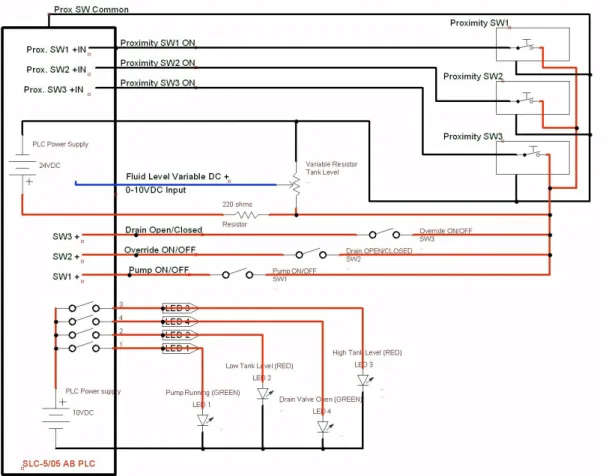
3. HOS
The HMI override station is a connection box with a direct electrical connection to the PLC (see Appendix B for diagram). At the HOS, a command is sent as an electrical signal in the form of a change in voltage or current to the PLC and is received by an I/O module. The I/O module will update the CPU module with the new sensor status using a
shared bus located on the PLC rack and ensure all stations are updated with the status of the system control, fill pump or drain valve as changes are made at the HOS.
Figure 9. HMI pump status indicator and controls
The HOS has four LED lights that operate on 10VDC and three single-pole single-throw (SPST) switches that control the flow of 24VDC to the PLC. The LED lights are comprised of two red and two green lights.
Figure 10. PLC I/O modules their slot locations 0–3 (left to right)
The two red LED lights are illuminated by a 10VDC signal from the AB 1746-NO4V analog I/O module (PLC slot 2) when a low or high level is indicated at the FLSD. The two green LED lights are indicators for the fill pump operation and drain valve operation. The green LED lights are illuminated by the AB 1746-NO4V analog I/O module (PLC slot 2) with 10VDC in the event that the ladder logic conditions have been
met by the HMI or the HOS to order the pump or valve to turn on. The indication for the pump or valve is strictly controlled by the PLC and will indicate at the HOS regardless of the station that is in control.
The three electrical switches on the HOS are used for taking control of the AFTL at the HOS, commanding the fill pump on or off and commanding the drain valve open or closed as desired (see Figure 11).
Figure 11. HMI override station controls and indications
The HMI override switch controls a 24VDC electrical signal that is sent to the PLC signaling control override of the system in the event of an emergency or when only manual local control is desired. The remaining two switches operate the same way but the PLC interprets the change in electrical voltage as pump and valve controls where 0 VDC is pump off or valve closed and 24VDC is pump on or valve open.
V.
DIGITAL I/O LAB
The digital I/O lab is the sub-component of the MCS testbed that provides a platform allowing others to experiment with MCS systems using Digital I/O. The ability to analyze the data packets and compare between input command and output response is a critical aspect of the digital I/O lab.
A. CONCEPT OF OPERATIONS
The digital I/O lab resembles an authentic control system that interacts with a third-party actuator through a specialty digital protocol. Functional requirements of the digital I/O lab are listed in Table 2. The digital I/O lab consists of four components: the HMI (supervisory segment), the PLC (control segment), mechanical (robot) arm and proximity sensors. The robot arm moves an object between sensors, as commanded. The proximity sensors detect the location of the object and update their status to the PLC digitally. The HMI will interface with the PLC and display the status of the sensors and the robot arm to the HMI operator. The HMI operator can command the arm to move an object between sensors and be informed of the condition of that operation.
1. Digital I/O Human Machine Interface
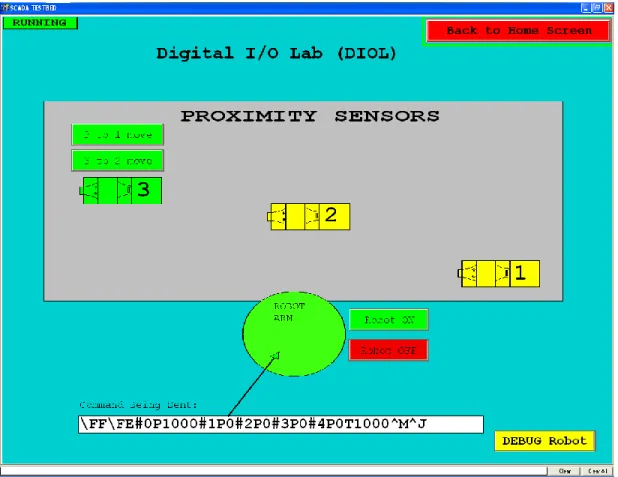
The digital I/O HMI is a graphical display of the sensors and status available in the lab. The digital I/O HMI allows the operator to command the arm to move an object between proximity sensors, to view the current command being sent to the arm and to view alerts that may need the operator’s attention (see Figure 12).
2. Programmable Logic Controller
The PLC in the digital I/O lab is the same described earlier (see Chapter III). The digital I/O lab will utilize a separate I/O module than that of the AFTL, but the concept of operation is the same.
3. Robot Arm
The robot arm resembles devices used in a manufacturing setting, and fills the role of a third-part actuator requiring communication of specific commands sent from the controlling station (HMI) and the output device (robot arm). The robot arm is a servo-driven commercial arm that is directly connected to the PLC CPU module using a RS232 serial connection. The robot arm is controlled using a pre-formatted command signal that is sent from the HMI. The robot arm can be used to move an object from one location to another. Each location has a proximity sensor that will provide feedback to the PLC to determine if the command to the robot arm is successful.
4. Proximity Sensors
Proximity sensors are used to detect the presence of the object moved by the robot arm. The proximity sensors have a digital output that signals the PLC when the object is placed on the sensor or removed from the sensor. The sensors state is used to determine the current status of the digital I/O lab and the completion status of the command issued to the robot arm. Proximity sensors are used quite frequently in industrial settings and assembly line systems.
B. DESIGN
The design section will describe each component of the digital I/O lab listed in the CONOPS section above and the functions needed by each component to support the functional requirements of the digital I/O lab (see Table 2). The functionality of each component is outlined below, but implementation details are deferred to later in this chapter. The digital I/O lab shares the Allen Bradley PLC used in the AFTL, but utilizes the RS232 port on the CPU card to send commands to the robot arm and requires different I/O modules to monitor the status of the proximity sensors influenced by the robot arm. The digital I/O network shares the same components and network as described in Chapter IV. See Table 2 for functional requirements associated with the components discussed below.
1. Controlling the Robot Arm
At the HMI, the robot arm is controlled using command buttons and feedback from proximity sensors. Each proximity sensor and its status are represented graphically at the HMI. There are two buttons displayed as options at each proximity sensor when it is active. These buttons represent the choice of movement that the robot arm can perform. Each button will execute the commands the robot requires to move an object from one proximity sensor to another. As the robot is in motion, each command that is transmitted to the robot arm is displayed on the HMI. The HMI operator cannot send new commands to the robot arm until the robot arm has completed the task of moving the object to the new proximity sensor.
The robot arm can be commanded to a starting and stowing position using the start and stop buttons located on the HMI. The start button will place the robot arm in a position ready to retrieve and move an object. The stop position will order the robot arm to shut down completely and wait for a start command. The stop position is the offline position for the robot arm when the digital I/O lab is not in use.
Requirement traceability: R12
2. Moving Objects Using the Robot Arm
At the HMI, each proximity sensor status is displayed and if an object is present on the proximity sensor the HMI will represent that status. When an object is present on the proximity sensor the HMI will provide choices to the user in the form of buttons. Each button will allow the operator to move the object between proximity sensors as desired. Once the command is given to the robot arm to move the object between sensors then the robot arm will perform the movements necessary to pickup and deliver the object onto the desired sensor.
3. Dynamically Displaying the Status of the Proximity Sensors
At the HMI, A graphical representation and a text status will be displayed for each of the three proximity sensors. When a sensor detects an object, the status of the sensor will change color indicating that the sensor detects an object. Likewise if the sensor no longer senses an object it will indicate as such.
Requirement traceability: R13
4. Displaying the State of the Robot Arm and Commands Issued
At the HMI, The robot arm has three main positions that are tracked: start, stop and in motion. The exact status of the command issued to the arm is displayed as an ASCII representation of the bits used to issue the command to the robot arm. Once the arm receives each command, the next command will be displayed until the robot arm has completed the movement. The robot will return to the start position upon completion of the movement.
At the robot arm, the movement of the arm can be observed and verified visually by the HMI operator to ensure its proper execution.
Requirement traceability: R14, R15
5. Displaying Indications When an Error has Occurred
At the HMI, when all three proximity sensors indicate no object the HMI will indicate there is no object present and prompt the operator to replace an object on a sensor to continue. Additionally when all three sensors have objects on them the robot arm cannot move to an empty sensor and therefore an error will be displayed by the HMI indicating that all the sensors are full.
Figure 12. DIOL HMI screenshot
C. IMPLEMENTATION
Implementation of the Digital I/O lab design described earlier in the chapter is described in this section in detail. A state diagram for the DIOL can be found in Appendix E.
1. Engineering Workstation and HMI
The engineering workstation used in the Digital I/O is the same as that described in the AFTL. The HMI is implemented using graphical buttons and colors to display the status of the robot arm and each proximity sensor. The DIOL HMI uses Visual Basic programs that read a text file of pre-formed commands to execute movements between sensors. Logic is used at the HMI to decide if a button is available to be displayed or changes color based on the status of each proximity sensor and the robot arm. The DIOL
HMI display includes a “DEBUG” section from which the operator can send commands directly to the robot arm, bypassing the Visual Basic program. The debugging capability allows the operator to perform robot movements one at a time to ensure the robot execute each command properly.
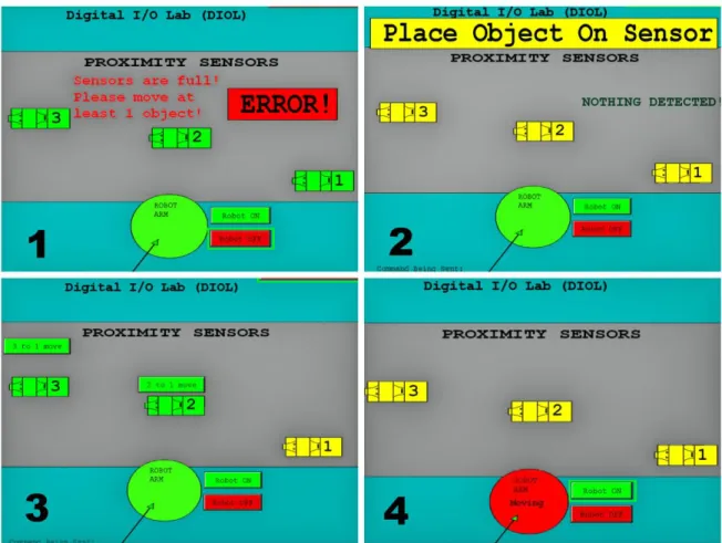
In the event of an error involving the proximity sensors or the robot the HMI has been programmed to identify the errors to the operator. An example of the errors can be found in Figure 13, which shows the various proximity sensor states. Figure 13 is labeled as follows: (1) Error: all three sensors active robot arm cannot move any of the three objects, (2) Error: No object for the robot arm to move because none of the sensors are active and robot arm is not in motion, (3) Normal: 2 sensors active, only choice for the robot arm to move is to sensor 1, (4) Normal: robot arm in motion with object. See Figure 12 for a screenshot of the DIOL HMI and Chapter IV for details on the HMI and engineering workstation.
Figure 13. DIOL HMI, various proximity sensor display states
2. Digital I/O PLC
The PLC in the digital I/O Lab is the same used in the AFTL lab (see Chapter III). The digital I/O lab requires only one I/O module and channel 0 output on the PLC CPU module to retrieve and update information about the proximity sensors and send commands to the robot arm. The CPU module output channel 0 interfaces with the robot arm using the built in RS232 port and cable connection located on PLC CPU module. The proximity sensors are wired directly to the digital I/O module located in slot 3 of the PLC. The PLC receives HMI commands and can issue commands to the robot arm based on the internal ladder logic program. The operation of the ladder logic program, interface between the HMI and PLC and HMI operation using “tags” are identical to those described previously (see Chapter IV).
While the interface and basic operation of the HMI, PLC and sensors are the same in the digital I/O lab; the ladder logic program used to operate the robot arm and update the status of the three proximity sensors is different. The ladder logic is composed of a main program and two subroutines. The main program enables the two subroutines when the digital I/O lab HMI is enabled. One subroutine monitors the proximity sensor for change in status and the other interfaces with the robot arm to transmit commands received from the HMI. When the Digital I/O Lab HMI is open, the PLC will constantly monitor the proximity sensors for status changes and allow the HMI operator to transmit commands to the robot arm via channel 0 on the PLC CPU using the RS232 port.
3. Robot Arm and Proximity Sensors
The robot arm is a Lynxmotion AL5D mechanical arm with four servos, connected to a SSC-32 servo controller and interface card. The SSC-32 servo controller interface receives commands from the PLC on the RS232 connection and executes them. The four servos provide range of motion in three dimensions, and a clamping action on the hand of the robot arm. The servos have rotors that will rotate to a position as commanded. Each servo is numbered and can be addressed in order to command it to move. The servos are commanded to a position by an integer that represents where on the scale of motion the servo should place its rotor. Once the command is received, the SSC-32 servo controller will compare the current rotor location to the commanded rotor location and move the rotor until the difference between the ordered and actual position is zero. The difference between the ordered and actual position of the rotor is called the error [23].
The servo controller commands are formatted in the following pattern: “#0P1000#1P1500#3P2000T1000/n”. Where the integer following every “#” represents the servo to be addressed. The servos are numbered from the base to the hand clamp as 0–4 respectively. For example, “#1” addresses the number 1 servo. Immediately following the servo address is the letter “P,” which represents a command for the ordered position to place the rotor. The integer following “P” is the numerical representa
![Figure 1. Basic PLC Group used in MCS systems, from [14]](https://thumb-us.123doks.com/thumbv2/123dok_us/441951.2551120/24.918.241.675.121.559/figure-basic-plc-group-used-mcs-systems.webp)