PROCESS CONTROL PROGRAM AS AN ELEMENT
OF DISTRIBUTED CONTROL SYSTEM
Dragan R. Milivojevic
Head of the Department of Industrial informatics, Mining and metallurgy institute Bor, Zeleni bulevar 35, 19210 Bor, Serbia
e-mail: [email protected]
Vladimir Despotovic
Technical faculty of Bor, Vojske Jugoslavije 12, 19210 Bor, Serbia
e-mail: [email protected]
Visa Tasic, Marijana Pavlov
Mining and metallurgy institute Bor, Zeleni bulevar 35, 19210 Bor, Serbia
e-mail: [email protected], [email protected]
Abstract. Monitoring and control of technological processes in many production units demands transfer of infor-mation and interaction with the process from remote distances. For this purpose, the process control systems have been designed and developed. In the first project phase, the separate production lines were covered by independent control systems. In the second phase, the individual control systems were interconnected in a large heterogeneous industrial network, forming the distributed control system (DCS). This paper presents results of development of specific hard-ware and softhard-ware solutions for monitoring of technological processes, with special regards to communication systems structure.
Keywords: process control, distributed control system, industrial network, measuring, software solutions.
1. Introduction
The plant process control systems are based on de-dicated industrial computers able to get the informa-tion of process parameters and execute acinforma-tions in order to keep or change relevant process conditions. Microprocessor measuring station (MMS) fully de-signed and developed at the Department of Industrial Informatics of the Institute of Mining and Metallurgy [4] is used as a programmable logic controller (PLC). The master PC is added as an interactive workstation, forming an entity which is a core of complex distri-buted control and monitoring system (see Figure 1).
MMS was designed with suitable performances for monitoring and control of relatively slow technologi-cal processes. It is based on MC68HC11 microcont-roller and 8-bit architecture. The main module, one board computer (OBC), contains residential executive system [5, 8] in EPROM and adequate RAM configu-ration. The input/output logic is designed to support 64 independent analog input channels and 2 × 64
digital inputs and outputs. The 8-bit A/D converter is integrated in microcontroller itself. The serial commu-nications are performed using specially designed lo-gic, connecting MMS to standard serial input/output PC port. The executive code of self-test programs, operational and communication program modules are contained in EPROM [6]. Although microprocessor measuring station can be an autonomous system unit, it is more frequently used as a node in a very simple network (entity), which contains MMS and PC work-station, Figure 1. The complex communication sub-system on both sides was developed for efficient entity functioning.
network runs according to master-slave principles. The PC as a master node is starting the session, maintaining the data transfer and regular end of session. The MMS has to respond to every PC demand. P R O C E S S IN PUT/OU TPU T M O DU LES OBC (MC68HC11) MMS PC -Workstation
E N T I T Y
P R O C E S S IN PUT/OU TPU T M O DU LES OBC (MC68HC11) MMS PC -Workstation P R O C E S S IN PUT/OU TPU T M O DU LES OBC (MC68HC11) MMS PC -Workstation
E N T I T Y
Figure 1. Simplified block diagram of a plant control system
2. Process control program – an application for real time monitoring and control
The special SCADA (Supervising Control and Da-ta Acquisition) real-time application, working in Windows environment, is developed in order to sup-port MMS functions and to perform data transfer, analyses and real-time interpretation of results. It is based on client/server architecture running on both master and remote stations, enabling integration in a complex distributed control and monitoring system. Let us call this program in further text Process Control Program (PCP). PCP is developed using Microsoft Visual C++ development kit [12]. Microsoft Foun-dation Class (MFC) library was used as a framework for manipulation with windows, menus and dialogs. Single Document Interface (SDI) with Document/ View architecture was used. The principle is that all the variables are declared in Document class, while visual representation of data is performed in View
class. PCP has a complex structure and consists of several modules. Main program modules are designed for:
• communication with MMS,
• data acquisition, real-time data processing and re-sults presentation,
• interaction with technological process according to appropriate algorithm and values of monitored parameters,
• creation of reports, data archiving, off-line data processing, database management.
All of the PCP functions, except the first one, are time irrelevant, and the response time for them is not critical [11]. But, the communication is timely critical. ASP requires an uninterrupted session controlled by PC. That is the reason why some PC resources (serial communication port, for example) must be controlled by PCP during the complete data transfer in both directions. The MMS responds with a portion of measured data, or as an acknowledgment to a com-mand sent from PC within the same communication session. In other case, the message transfer is con-sidered unsuccessful and the data are lost.
The collected data are stored in database, in un-compressed or un-compressed form. File management class including functions for data archiving is respon-sible for this task. Further processing consists of num-ber of actions:
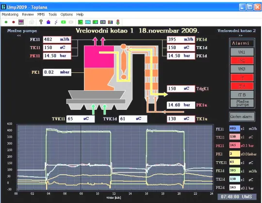
• data processing for graphical display (dynamic screens, time trends, tabular form) (see Figure 2),
• data processing for alarm system,
• data processing for distribution over LAN,
• forming of daily and monthly archives.
Interactions with technological process are perfor-med according to an algorithm for remote control, considering the actual values of measured parameters. The appropriate commands are generated and sent to MMS, which are executed via actuators.
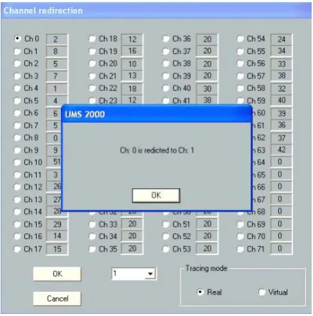
In order to display data in the user demanded way, independent of channel’s order in a communication message, Channel Switch class has been created. An appropriate dialog box is generated in order to enable user friendly interface for manipulation with input sig-nals to PCP, independent of their physical connections to MMS (Figure 3).
Figure 3. Channel redirection
Other classes are responsible for configuration of different parameters of PCP and MMS, such as samp-ling rate, communication frequency, type of measu-ring, number of analogue and digital channels, time synchronization etc.
3. The PCP and MMS communication software modules
The PCP communications program module con-tains driver for communications with MMS. Commu-nication protocol is ASP (Asynchronous Serial Proto-col) [4]. Communication class is the most important class of PCP, with the following main objectives:
• request for communications,
• connection establishment,
• data transfer,
• control of transfer quality,
• state indication of network nodes.
Functions of the Communication class are respon-sible for configuration of the serial PC port by setting its parameters to appropriate values. It is performed every time the session starts executing the following program sequence1 [2, 9]:
mov dx,02FBh
(Line Control Register – LCR)
1
Intel chip assembler language
mov al, 83h
(83h = No parity, 8-bit character, 1 stop bit : N81)
out dx,al
mov dx,02F8h
mov al,06h (06h = 19200 bps)
out dx,al mov dx,02F9h
(Interrupt enable register)
mov al,00h
(00h= disable interrupt)
out dx,al mov dx,02FBh
(LCR)
mov al,03h
(polling)
out dx,al
It is important that the port configuration has to stay unchanged until the end of the session. On the other hand, other active applications running at the same time can reconfigure the port during the session. PCP has to prevent that. In order to satisfy this re-quest, the priority of the PCP has to be increased. Namely, Windows operating system allows concurrent executions of multiple tasks (processes) allowing each task to have limited time slices on the CPU. To keep the system balanced, threads are given priorities so that more critical threads are scheduled more frequent-ly or given longer time slices. User applications are usually given normal priority. It means that custom applications run using the computer resources with equal rules. If there is a need, it is possible to increase the process priority level. There are six priority levels corresponding to numerical values expressed by numbers from –15 to 15, listed below:
REAL TIME_PRIORITY_CLASS 15 HIGH_PRIORITY_ CLASS 2 ABOVE_NORMAL_PRIORITY_CLASS 1
NORMAL_PRIORITY_CLASS 0 BELOW_NORMAL_PRIORITY_CLASS -1
IDLE_PRIORITY_CLASS -15
The priority class of the target process can be changed using a function SetPriorityClass [10]. The following program sequence chooses the priority of the PCP:
HANDLE hProcess=GetCurrentProcess(); if (prioritet == "Realtime")
SetPriorityClass(hProcess,
REALTIME_PRIORITY_CLASS); else if (prioritet == "High")
SetPriorityClass(hProcess, NORMAL_PRIORITY_CLASS); else if (prioritet == "Low")
SetPriorityClass(hProcess, IDLE_PRIORITY_CLASS);
else SetPriorityClass(hProcess, HIGH_PRIORITY_CLASS);
Practical realization of process priority level order-ing is performed by simple choosorder-ing of a priority in a menu in the dialog box given in Figure 4.
Figure 4. PCP dialog box for Serial I/O port configuration and priority ordering
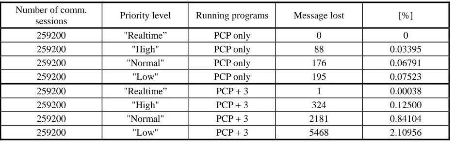
Table 1. Experimental results
Number of comm.
sessions Priority level Running programs Message lost [%]
259200 "Realtime” PCP only 0 0 259200 "High" PCP only 88 0.03395 259200 "Normal" PCP only 176 0.06791 259200 "Low" PCP only 195 0.07523 259200 "Realtime” PCP + 3 1 0.00038
259200 "High" PCP + 3 324 0.12500 259200 "Normal" PCP + 3 2181 0.84104 259200 "Low" PCP + 3 5468 2.10956
PCP running in the "Realtime" or “High” priority level guaranties efficient communications with MMS. In order to check the efficiency of communications, the following experiment was performed: system was tested for the period of three days, having 259200 communication sessions (every second). Ten tests were performed (three days each) and average results were summarized in Table 1. Two program environ-ments were chosen:
• PCP is the only running process (excluding the system processes),
• PCP is running concurrently with three other user processes.
The results are summarized in Table 1. It is ob-vious that the best effects are obtained with "Real-time” priority level, but considering the usual requests, the "High" priority is acceptable as well. The number of lost messages in upper half of the table could be explained as an influence of execution of Windows OS routines dealing with communication port. The results shown in lower half of the table are
the consequence of interactions with other user pro-cesses.
The communications on MMS side are handled by its operational program, which is a kind of real-time executive system. It has a modular structure, designed for measuring, data processing and process control. One of the most important modules of real-time exe-cutive system is communication module, responsible for information transfer between MMS and PC workstation. The MMS is a slave node in entity net-work and the communication session starts as a quite stochastic event. That is the reason why the data transmission has to have the highest priority level compared to other MMS functions. It is provided by priority ordering mechanism [10].
The main step in communications initialization is programming of serial I/O for desired operational re-gime. It is performed by execution of the following program sequence2:
{Receiver Sleep! - Option}
2
Procedure Sleep; begin
pshx; psha; ldx INDEX;
ldaa $20; {set DWOM-bit to SPCR} staa x[SPCR];
ldaa $30; {19200 bps to BAUD reg.} staa x[BAUD];
ldaa $08; {set WAKE-bit to SCCR1} staa x[SCCR1];
ldaa $2E; {set RIE, TE, RE, RWU to SCCR2} staa x[SCCR2];
clr [SemRcv];
cli; pula; pulx; rts; end;
This procedure prepares MMS to detect communi-cations interrupt request. The current process stops and the communication service routine takes place. Actual command from PC workstation can now be received, and appropriate response sent back. The response can be either MMS status, remote command execution status, measured data, or all of them. The general message format (according to ASP protocol) contains all of these fields, a shown in Figure 5.
Header Status Date Time DATA Control
Figure 5. General MMS message format
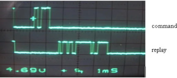
During the data transfer (in both directions) MMS operational program is busy and cannot perform usual tasks such as measuring or process control. In some cases, data transfer can take more then 50 ms per session. To increase the measuring and control effi-ciency, the communication message can be shortened. If the sampling frequency is critical, header, date and time fields can be omitted.
For special applications with small number of pro-cess parameters, the data field contains just the ordinal number and input channel values. The real time is
reconstructed on PC using starting time, sampling rate and received ordinal number. The measuring perfor-mance of MMS becomes more efficient and response time improved in this way. Results empirically achie-ved in practice show possibility of performing data transfer in less then 5 ms (Figure 6), allowing MMS response time of 10 ms.
The MMS working regime, the communications mode and frequency (polling rate) may be chosen from PCP menu, Figure 2 (“Options”), or locally on measuring station.
Figure 6. Time diagram of shortened communication session
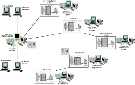
4. Integration of mms and PCP in distributed control system
Realized Monitoring Measuring Station and Pro-cess Control Program are applied mainly in metallurgy industry. Production plants are often dislocated in a several kilometers wide area. To cover the main process parameters and monitor them in a real-time, it is necessary to realize a distributed control system (DCS). The complex decentralized industrial network is built for this purpose [1]. The basic network nodes are entities consisted of MMS and PC workstation (server in network configuration), running appropriate PCP. The remaining network nodes (clients in network
Figure 7. The overall block schema of realized industrial network structure
5. Conclusion
The realized distributed control system is an example of practical solution for complex industrial network built of heterogeneous nodes. Communica-tion between MMS and PC workstaCommunica-tion is realized using the specially designed protocol (Asynchronous Serial Protocol) with defined priority levels, which guaranties efficient and reliable data transfer. The main advantage of ASP is minimal length of header and control characters compared to the amount of useful data to be transferred.
Another significant characteristic of the realized distributed control system is the possibility of multi-plying source databases at secondary network nodes (clients in realized industrial network), enabling mul-tiple backup in real-time.
The system showed good stability and resistance to external influences. The system response time varies from plant to plant, depending on actual process de-mands. The possibility of distant monitoring is very important for making different business and produc-tion strategy decisions on time. In that way, manage-ment at different levels is able to monitor and follow the relevant process parameters in real time. Appro-priate data analyses and creation of reports can be also performed on client side at any time. It can be hori-zontally upgraded by adding the new client PCs.
In a near future vertical network expansion is planned, by integration with two other information systems. Namely, in order to control high level of air pollution, which is a direct consequence of controlled technological process, a global network air quality
monitoring system independent of our DCS is in use. Having the picture of technological process and ecolo-gical parameters at the same time will be very impor-tant for making real time analyses and decisions in order to reduce the environment pollution with opti-mal process production.
Integration with the existing information system for electrical power supply optimization and costs re-duction is the other important step in overall increase of efficiency. This information system covers two transformer stations and all power consumers at dif-ferent production plants. Simultaneous monitoring of technological process parameters and electrical power consumption is necessary to make the technological processes more efficient and decrease electrical energy costs.
Acknowledgements
This paper is partly supported by the Grant of the Ministry of Science and Technological Development of Republic of Serbia, as a part of the Project EE-18016 within the framework of Technological Deve-lopment Program.
References
[1] G. Held. Ethernet networks. John Wiley & Sons, 2003.
[2] M. Joseph. Real-time Systems. Prentice Hall Interna-tional, UK, 1996.
[4] D.R. Milivojevic. Microprocessor Measuring Station as an Element of Industrial Control Systems. PhD.
Thesis, University of Belgrade, Techical Faculty Bor, l 2008.
[5] D.R. Milivojevic, M. Pavlov, V. Tasic, V. Despoto-vic. The Software Structure and Principles of Main Task Scheduling in an Executive System. Journal of Theoretical and Applied Information Technology, Vol. 5 , No.3, 2009, 270-276
[6] D.R. Milivojevic, V. Tasic. Some Software Elements of the Microprocessor Measuring Station. Acta Electro-technica et Informatica, Vol.7, No.2, 2007, 64-68.
[7] D.R. Milivojevic, V. Tasic. MMS in Real Industrial Network. Information Technology and Control, Vol. 36, No.3, 2007, 318 – 322.
[8] D.R. Milivojevic, V. Tasic, V. Despotovic, M. Pav-lov. One Solution of Task Priority Ordering in Micro-processor Measuring Station. Information Technology and Control, Vol.38, No.1, 2009,67-71.
[9] R. Rector, G. Alexy. The 8086 BOOK. Osborne/ McGraw-Hill, Berkeley, 1980
[10] W.Roetzheim.: Borland C++ 4.5. Mikro knjiga, Beo-grad, Serbia, 1995.
[11] B.Stroustrup. Program Lenguage C++. Mikro knjiga, Beograd, Serbia, 1991.
[12] Web site: www.mycplus.com/tutorial.