1
Copyright © 2016. Vandana Publications. All Rights Reserved.
Volume-6, Issue-6, November-December 2016
International Journal of Engineering and Management Research
Page Number: 1-7
Study on the Analysis and Optimization of Brake Disc: A Review
Manjeet Singh1, Anand Baghel2, Janmit Raj3
1Research Scholar, Department of Automobile Engineering, Rustam Ji Institute of Technology, Tekanpur,
Gwalior (M. P.), INDIA
2,3Assistant Professor, Department of Automobile Engineering, Rustam Ji Institute of Technology, Tekanpur,
Gwalior (M. P.), INDIA
ABSTRACT
In view of significant increase in the research work on the brake disc in past few years, this article attempts to identify and highlight the various researches that are most relevant to analysis and optimization of brake disc. In the present article a keen review on the studies done on brake disc by previous researchers between (1998-2015) is presented. This literature review covers the important aspects of brake disc with the emphasis on material selection methods, thermal analysis, structural analysis, FEA and optimization of disc brake. This literature progressively discusses about the research methodology adopted and the outcome of the research work done by past researchers. This review is intended to give the readers a brief about the variety of the research work done on brake disc.
Keywords--- Brake disc, FEA, Optimization
I.
INTRODUCTION
Brake system is the most important safety feature of an automobile. Vehicle safety is one of the major research area in automotive engineering.
The brake system is used to retard the motion of the accelerating vehicle or to stop the vehicle within the smallest possible distance. Disc brake mainly consists of a cast iron disc bolted to the wheel hub and a stationary housing called calliper. To stop the wheel, friction material in the form of brake pads (mounted on calliper) is forced mechanically, hydraulically, pneumatically or electromagnetically against both sides of the disc [6]. Friction causes the disc and attached wheel to slow or stop. The working of brake disc is shown
Fig. 1: Disc Brake Working
II.
BRIEF DESCRIPTION OF BRAKE
DISC
In today’s growing automotive market the competition for better performance vehicle is growing enormously. To enhance the performance of disc brake the different materials are used for brake disc so that to get the better performance. The Disc brake discs are commonly manufactured out of grey cast iron. The SAE maintains a specification for the manufacture of grey iron for various applications. For normal car and light truck applications, the SAE specification is J431 G3000 (superseded to G10). This specification dictates the correct range of hardness, chemical composition, tensile strength, and other properties necessary for the intended use [9]. Some racing cars and airplanes use brakes with carbon fiber discs and carbon fiber pads to reduce weight. The disc brake rotor has two main parts: the hub and the braking surface. The hub is where the wheel is mounted and contains the wheel bearings. The braking surface is the machined surface on both sides of the rotor. It is carefully machined to provide a friction surface for the brake pads. The entire rotor is usually made of cast iron, which provides an excellent friction surface. The size of the rotor braking surface is determined by the diameter of the rotor. Large cars, which require more braking energy, have large rotors. Smaller, lighter cars can use smaller rotors. Generally, manufacturers want to keep parts as small and light as possible while maintaining efficient braking ability. The rotor is protected from water and dirt due to road splash by a splash shield bolted to the steering knuckle [13]. The outboard side is shielded by the vehicle’s wheel. The splash shield and wheel also are important in directing air over the rotor to aid cooling.
III. PREVIOUS RESEARCHES
3.1 Previous work done on the methods of material selection
2
Copyright © 2016. Vandana Publications. All Rights Reserved.
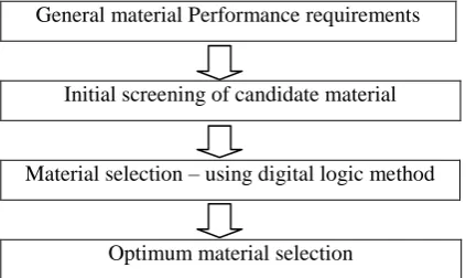
iron is higher which consumes much fuel due to high inertia [2]. To reduce automobile weight and improve fuel efficiency, the auto industry has dramatically increased the use of aluminium in light vehicles in recent years. In automotive industries, to achieve reduced fuel consumption as well as green house gas emission is a current issue of utmost importance. Malcolm P. Et al. [1], done a review of the disc materials used today by the automotive industry would show that there are some distinct classes of materials: low carbon iron, medium carbon iron, high carbon iron, alloyed iron, carbon composites, aluminium MMC materials and concluded that grey cast iron is the ideal material for the production of large quantities of high quality automotive components. The material is easily controlled to tight compositional requirements that satisfy the performance requirements of safety critical components such as brake discs the authors had attempted to show in this paper that cast iron far from being an old fashioned low tech material can, with the input of industry and research establishments. M.A. Maleque et al. [2], analyzed and evaluated the alternative solutions among cast iron, aluminium alloy, titanium alloy, ceramics and composites. The materials selection chart is a very useful tool in comparing a large number of materials at the concept design phase which could be reflected the fundamental relationships among particular material properties and be used to find out a range of materials suitable for a particular application as shown in Fig. 2.
General material Performance requirements
Initial screening of candidate material
Material selection – using digital logic method
Optimum material selection
Fig.2: Flow chart of material selection method.
The plot of performance indices against all the candidate materials generated by the author is shown below in Fig. 3.
Fig3: Plot of performance index (γ) against all candidate materials
The digital logic method showed the highest performance index for AMC 2 material and identified as an optimum material among the candidate materials for brake disc. In the digital logic method, the friction coefficient and density were considered twice for determining the performance index and the cost of unit property. This procedure could have overemphasized their effects on the final selection. Further the team of researchers G. Cueva et al. [3], studied three different types of gray irons viz. one grade 250(GI250), one high-carbon (GIHC), one alloyed with Ti (GI250Ti) and a compact graphite iron. The Chemical composition (wt. %) and mechanical properties of irons are shown in table 1. The pin-on-disc wear tests carried out with CGI and three different gray irons allowed to conclude. The setup of pin-on-disc wear test is shown below in Fig. 4. For given applied pressures, the wear of compact graphite iron is higher than that of gray irons. The wear tests had been carried out as follows: a cyclic pressure of 0.7, 2 and 4MPa was applied through the pin to the spinning rotor (500 rpm). Pressure was applied for 1 min leaving the rotor spinning unloaded for the next 3 min, the total cycle being 4 min long. During the cycles, a blower
cooled the pin–rotor system.
Fig. 4: Schematic representation of pin-on-disc wear-testing machine
The test lasted 20 h, with the completion of 300 cycles (loading–unloading). During the cycles, the temperatures reached by pins were determined by
Table 1: Chemical composition (wt. %) and mechanical properties of irons.
GI250 GIHC GI250Ti CGI
C 3.54 3.73 3.49 3.63
Si 2.15 2.07 2.27 2.06
Mn 0.51 0.78 0.53 0.51
P 0.054 0.058 0.052 0.04
S 0.1 0.085 0.09 0.015
Ti 0.012 0.014 0.028 0.014
Cu 0.69 0.56 0.71 0.47
Cr 0.34 0.27 0.060 0.035
Sn 0.061 0.039 0.064 0.045
Hardness
(HB) 195±5 180±5 195±5 220±5
UTS
(MPa) 255 240 255 460
3
Copyright © 2016. Vandana Publications. All Rights Reserved.
independent of the iron. During gray irons tests, at given applied stresses, practically the same friction forces and temperatures were observed, independent of the grade. Compact graphite iron, on the other hand showed greater friction forces and temperatures than those observed in gray irons. During CGI tests using lower applied pressures (3.3, 1.7 and 0.4MPa), carried out to reach the same order of friction forces obtained for gray irons, the author observed that the wear is greater or at least the same of that observed for gray irons. So in that context In the further study C.Radhakrishnan et al. [4],
analyzed the thermal behaviour of the ventilated brake disc with Titanium alloy (Ti 550) and conventional grey cast iron. The reason behind choosing the Ti 550 was that it is a high strength, forgeable alpha beta alloy. It has superior tensile and fatigue properties compared to Ti 6-4 combined with good elevated temperature tensile and creep properties up to750°F (400°C). Ti 550 had also found applications in high performance automotive engines. The alloy has good superplastic forming properties and an excellent balance of strength and toughness. They compared the Ti 550 alloy and grey cast iron material brake disc based on the wear resistance and thermal gradient properties, they calculate the heat dissipation and force created by these two materials and found that Ti 550 alloy is best on the thermal analysis (table 2).
Table 2: Result comparison.
Material Type
Total deformat ion(mm)
Equivale nt stress(N/ mm2)
Temperature Distribu tion(oC)
Grey cast iron
0.0125 18.274 537.36
Ti550 0.00006
7857
3.9911 474.75
3.2 Previous works done on thermal analysis of brake disc
Many researchers investigated the heat generation phenomenon between contact surfaces in automotive clutches and brakes to predict the temperature distribution and especially the maximum temperature during the clutch engagement and braking to avoid failure before an estimated lifecycle. This process is very complex because of the following characteristics pressure, coefficient of friction and sliding speed. The researchers used different numerical techniques such as the finite element and finite difference methods to compute the sliding surface temperature. The researchers
V.M.M.Thilak et al. [5], investigated the suitable hybrid composite material which is lighter than cast iron and has good Young’s modulus, Yield strength and density properties. Aluminium base metal matrix composite and High Strength Glass Fiber composites have a promising friction and wear behaviour as a Disc brake rotor. The transient thermo elastic analysis of Disc brakes in repeated brake applications had been performed (Fig. 5). The effects of the friction material properties on the contact ratio of friction surfaces are
examined and the larger influential proper-ties are found to be the thermal expansion coefficient and the elastic modulus.
Fig. 5: Temperature distribution
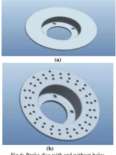
It was observed that the orthotropic Disc brakes can provide better brake performance than the isotropic ones because of uniform and mild pressure distributions. The research indicated that S2 glass fiber was the suitable material for the braking operation and all the values obtained from the analysis are less than their allowable values. The author concluded that the design is safe based on the strength and rigidity criteria. A year later Ameer Fareed [6], studied about the model of a disc brake used in Honda Civic. Coupled field analysis (Structural+Thermal) was done on the disc brake. Analysis was also done by changing the design of disc brake, Actual disc brake has no holes, design is changed by giving holes in the disc brake for more heat dissipation (Fig. 6). The materials used are Cast Iron. He proposed a new conceptual caliper design to decrease the thermal deformation at high temperatures. The modular caliper is an assembly unit made up of simple and easy to manufacture parts. The Existing caliper was first analyzed at cold working conditions without taking into account the effects of thermal expansion.
(a)
(b)
4
Copyright © 2016. Vandana Publications. All Rights Reserved.
The maximum stress was lower for Al 2219 than the Al 6061 brake caliper. The existing brake was analyzed at 300ºF. The caliper showed high thermal stresses and displacement as compared with the previous case that was due to the thermal expansion of caliper body. The modular design was analyzed without considering the effects of thermal expansion. This was done to study the amount of deformation due to tangential Force and pressure loading. These results were used to study the increase in deformation in the caliper at high temperatures. The modular brake was then analyzed using a nodal temperature of 300ºF. The displacement increased as compared with the previous case. This is due to the thermal expansion of the individual parts in the assembly. The author concluded that the thermal displacement in the modular caliper is lower than the conventional caliper by 8.56 %. In another study Ishwar gupta et al. [7], depicts the work on thermal analysis through finite element analysis of rotor disc of disc brake of BAJA SAE 2013 vehicle. The Dimensions of an existing Maruti 800 car’s disc rotor of disc brake are taken. For thermal analysis they considered 5 rotor disc materials Grey cast iron, Aluminium metal matrix composites, E glass fibre, Ceramic & Hard rubber. The maximum temperature obtained in grey cast iron rotor disc was at rubbing surface & was observed to be 167.56 ˚c. The grey cast iron rotor disc is safe based on strength & stability criteria. To achieve a best combination of parameters of rotor disc like size, type & materials, & thermal analysis for 5 different material combinations were done & results were validated using digital logic & fracture analysis method. By comparing the different results obtained from FEA & analytical analysis the study concluded that rotor disc of grey cast iron having 10mm thickness & 215mm diameter is the best suitable combination for the present application. The study conducted by A. Belhocine et al. [8], investigated and analyzed the temperature distribution of rotor disc during braking operation using ANSYS Multiphysics. They uses the finite element analysis techniques to predict the temperature distribution on the full and ventilated brake discs and to identify the critical temperature of the rotor. The analysis also gives us the heat flux distribution for the two discs. In this study, the author presented results of the thermal behaviour of full and ventilated discs in a transient state. By means of the computer code ANSYS 11, they studied the thermal behaviour of a gray cast iron (FG 15). In addition, the influence of disc ventilation on the thermal behaviour of the discs brake was analysed. The numerical simulation shows that radial ventilation plays a very significant role in cooling of the disc during the braking phase. Through the numerical simulation, the author concluded that the quality of the results concerning the temperature field is influenced by following parameters:
(i) Technological parameters illustrated by the design. (ii) Numerical parameters represented by the number of
elements and the step of time.
(iii) Physical parameters expressed by the types of materials.
On the basic of these observations, the result depicted that the geometric design of the disc is an essential factor in the improvement of the cooling process of the discs as shown in Fig. 7 and Fig. 8.
Fig.7: Temperature distribution of a full (a) and ventilated disc (b) of cast iron (FG 15)
Fig.8: Temperature variation through a radius for both designs of cast iron (FG 15)
3.3 Previous works done on structural analysis of brake disc
5
Copyright © 2016. Vandana Publications. All Rights Reserved.
Brake disc design is safe based on the Strength and Rigidity Criteria. In further work V. Chengal Reddy [10], conducted Coupled Analysis (Structural & Thermal analysis) that was performed in order to find the strength of the disc brake which gives the results of the three materials Carbon-Carbon Composites, Maraging Steel and Cast Iron. The analysis concluded that Maraging Steel gives less nodal temperature value when the loads are applied. Therefore Maraging Steel material is preferred over the existing materials. Table depicts all the values obtained from the analysis are less than their allowable values. Comparing the different results obtained from analysis the analysis concluded that ventilated type disk brake is the best possible for the present application and maraging steel is best material for Disc Brake and the brake disk design is safe based on the strength and rigidity criteria. In another study N. Balasubramanyam [11], aimed to study the given disc brake rotor of its stability and rigidity(for this Thermal analysis and coupled structuralanalysis is carried out on a given disk brake rotor). He suggested Best combination of parameters of disk brake rotor like Flange width, Wall thickness and material. An Axis-symmetric analysis of disc brake had been carried out using Plane 77 and Plane 82 through ANSYS R 10.0 (F.E.A) software. A transient thermal analysis was also carried out using the direct time integration technique for the application of braking force due to friction for time duration of 4.5 seconds. The maximum temperature obtained in the brake disc for the Materials Grey cast Iron, AL-MMC, AMMC were 486.76, 29.232, and 30.307 respectively at the contact surface. Static structural analysis was carried out by coupling the Thermal solution to the structural analysis and the maximum Von Mises stress was observed to be 50.334 M Pa for Material 1, 211.98 M Pa for Material 2 and 586.7 M Pa for Material 3.Comparing the different results obtained from theanalysis, the study concluded that Cast Iron is the Bestpossible combination for the present application (Fig. 9).
Fig. 9: Static structural
The next study was carried out by K. Naresh Babu [12], depicts the work on structural analysis by coupling thermal analysis. An attempt to suggest a best combination of materials (like Cast iron, stainless steel, High strength S-glass fiber and Aluminium metal matrix composite), flange width and wall thickness used for disc brake rotor, which yields a low temperature
variation across the rotor, less deformation, and minimum von-misses stress possible. An Axis-symmetric analysis of disc brake had been carried out using elements Plane 55 and Plane 42 through ANSYS 12.0 (F.E.A) software. A transient thermal analysis was carried out using the direct time integration technique for the application of braking force due to friction for time duration of 4, 5 and 6 seconds. The maximum temperature obtained in S2- Glass brake disc at the contact surface was observed to be 125.3 °C. Static structural analysis was carried out by coupling the Thermal solution to the structural analysis and the maximum Vonmises stress in S2-Glass brake disc was observed to be 60.3 M Pa. To arrive at a best combination of parameters of the Disc Brake like Flange width, wall thickness and Material Transient Thermal and Structural Analysis for three different combinations in each of the four different materials were carried out separately and the results were compared. By Comparing the different results obtained from the analysis, the author concluded that disc brake with 12 mm flange width, 6.5 mm Wall Thickness and of material high strength S2-Glass is the Best possible combination for the present application and The Brake disc design is safe based on the Strength and Rigidity Criteria. In further work Ishwar Gupta [13], conducted the structural analysis of rotor disc of disc brake of BAJA SAE 2013 CAR through finite element analysis approach using ANSYS software. The Dimensions of an existing Maruti 800 car’s disc rotor of disc brake are taken. In this research the researches Obtained Von misses stress and Hoop Stress as shown in fig. 10 and Fig. 11 respectively.
Fig. 10: Von Misses Stress Distribution in Rotor Disc
6
Copyright © 2016. Vandana Publications. All Rights Reserved.
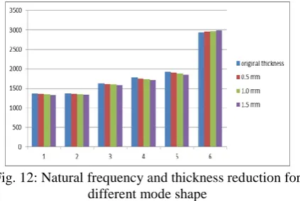
According to the given specification of rotor disc of disc brake the element type chosen for structural analysis was solid 20 node 95. From the analysis the research revealed that the obtained stresses are less than the design stresses and Maruti 800 Car’s rotor disc was suitable for his application. The next major study was done by A. Shahril et al. [14], conducted the natural frequency simulation test of disc brake functionality using computer aided engineering software. The finite element analysis technique was applied to predict the failure region on the brake disc and to identify the critical locations of disc brake. The disc brake rotor implemented on the front axle of Perodua Myvi 1.3 L model with grey cast iron materials which commonly used in industry was studied. The disc brake rotor surface thicknesses on both sides were reduced into 3 steps, 0.5 mm, 1.0 mm and 1.5 mm by using CATIA V5 software. Modal analysis was applied for each type of disc brake rotor model including normal brake disc surface to investigate the natural frequency for each type of brake disc rotor model. The results of natural frequency from each type of the disc brake rotor surface thickness were recorded. 24 types of mode shapes were obtained from the simulation and compared with 4 types of surface thickness. The same mode shape shows that the highest reduction mass becomes the lowest value of frequency and the highest mass becomes the higher value of the frequency as shown in Fig. 12. It is due to the effect of Inertia Force. However, at the last mode shape on highest reduction of mass shows, the frequency was maximum. From the research it is predicted that the instabilities are due to the repetitions of force applied to the rotor area.
Fig. 12: Natural frequency and thickness reduction for different mode shape
3.4 Previous works done on optimization of brake disc
Optimization is the act of obtaining the best results under given circumstances. In design of any engineering system, engineers have to take many technological and managerial decisions at several stages. Optimization can also be defined as process of finding the conditions that give maximum or minimum values of a function. In important study Harshall nikam et al. [15], Modelled, analysed and optimized in ANSYS Workbench 14.0 software package. Rotor dimensions were selected from 42 possible combinations of rotor diameter and thickness within allowable ranges. This sequential approach was adopted for rotor design of BAJA vehicle and proved to be effective. Using parametric optimization method. For
every optimization there are system optimization variables. These are the design variables which are independent quantities varying during optimization, in this research these are thickness and outer diameter. ANSYS Design Exploration is a design optimization application under ANSYS Workbench environment. Design Exploration is based on Design of Experiments. This together with various optimization methods help the program to develop an optimized structure based on selected input and output parameters. After setting up an analysis with a number of input (from CAD system) and output parameters (from ANSYS Mechanical results) there are steps that are to be run for final optimization.
Design of Experiments
Response Surface
Optimization
Table 3: parameters for optimization
Input Parameters
Output Parameters
Thermal Analysis
Structural Analysis
Thickness
Temperature
Safety Factor
Outer Diameter
Total Deformation
Goal-driven optimization is the most important step in optimization procedure. From the given table the objectives for each parameter and their degree of importance are selected. Based on the rates given by ANSYS appropriate Candidate was selected. For this design it was at 3.9 mm thickness and 190 mm outer diameter.
In another important study Avijit Singh Gangwar [16], optimized the brake disc. The geometric modelling and the simulation of the brake disc was done in simulation software CATIA. The author performed the FEA of brae disc on two materials viz. structural steel and chroma. The study concluded that the structural steel with thickness 2.8 mm can be used as material for brake disc. The performed by the researcher is shown below in Fig.13.
7
Copyright © 2016. Vandana Publications. All Rights Reserved.
IV.
CONCLUSION
This work has provided a comprehensive literature review of existing various research work carried out in terms of design, material selection methods, thermal analysis, structural analysis, FEA (Finite Element Analysis), Von misses stress, Hoop Stress, optimization and analysis of Brake Disc. An effort has been made to comprise all the important contributions to this area and highlighting the most pertinent literature available for investigating the Brake Disc. The concluding remarks and future work from the current literature survey are as follows:-
1. The review clearly indicates that the brake disc must have enough thermal storage capacity to prevent distortion or cracking from thermal stresses until the heat can bi dissipated.
2. Through the review it is apparent that the most of the designs based researches emphasis on strength and rigidity. The brake disc design is safe based on the strength and rigidity criteria.
3. Minimum factor of safety is kept more than 1 but as low as possible to avoid unnecessary weight of rotor which increases unsprung mass of vehicle.
4. Rotor thickness and diameter varies strong and maximum temperature on rotor surface significantly.
ACKNOWLEDGMENT
The review presented in this work is by no means complete but it gives a comprehensive representation of different thermal and structural analysis applied to the brake disc. The author wishes to apologize for the unintentional exclusions of missing references and would appreciate receiving comments and pointers to other relevant literature for a future update.
REFERENCES
[1] Malcolm P. Macnaughtan and John G. Krosnar, “Cast Iron – a brake disc material for the future?”, 2nd
International Seminar on Automotive Braking – Recent Developments and Future Trends, University of Leeds, UK. 14-15MAY 1998.
[2] G. Cueva , A. Sinatora , W.L. Guesser , A.P. Tschiptschin, “Wear resistance of cast irons used in brake disc rotors” , Wear 255 , pp 1256–1260,2013. [3] M.A. Maleque, S.Dyuti, “Material Selection Method in Design of Automotive Brake Disc” WCE 2010, London, U.K.,Vol III, June 30 - July 2, 2010.
[4]C.Radhakrishnan,Vengadeshprasadh.M,Vishnuhasan. A,Vimalraj.T,Velusamy.M, “Design and Analysis of Disc Brake with Titanium Alloy”,IJISET - International Journal of Innovative Science, Engineering & Technology, Vol. 2 Issue 5, pp 1044-1050, May 2015.
[5] V.M.M.Thilak, R.Krishnaraj, Dr.M.Sakthivel, K.Kanthavel, Deepan Marudachalam M.G, R.Palani, “Transient Thermal and Structural Analysis of the Rotor Disc of Disc Brake”, International Journal of Scientific & Engineering Research Volume 2, Issue 8, August-2011.
[6] Ameer Fareed Basha Shaik, “Structural and Thermal Analysis of Disc Brake With and Without Crossdrilled Rotor of The Race Car”, IJAERS/Vol. I/ Issue IV/July-Sept., pp 39-43, 2012.
[7] Ishwar Gupta, “Thermal Analysis of Rotor Disc of Disc Brake of BAJA SAE 2013 Car Through Finite Element Analysis”, International Journal of Engineering Research and Applications (IJERA) , International Conference On Emerging Trends in Mechanical and Electrical Engineering, pp 324-329, March 2014. [8] A. Belhocine, C.-D. Cho, M. Nouby, Y. B.Yi, A. R. Abu Bakar, “Thermal analysis of both ventilated and full disc brake rotors with frictional heat generation” Applied and Computational Mechanic, pp 5–24, 2014.
[9] K.Sowjanya, “Structural Analysis of Disc Brake Rotor”, International Journal of Computer Trends and Technology (IJCTT) – volume 4 Issue 7, pp 2295-2298 ,July 2013.
[10] V. Chengal Reddy, “Modeling and Analysis of FSAE Car Disc Brake Using FEM”, International Journal of Emerging Technology and Advanced Engineering Volume 3, Issue 9, pp 383- 389, September 2013.
[11] N. Balasubramanyam, “Design and Analysis of Disc Brake Rotor for a Two Wheeler”, International Journal of Mechanical and Industrial Technology (IJMIT) Vol. 1, Issue 1, pp 7-12, October 2013-March 2014.
[12] K.Naresh Babu, “Structural Design and Thermal Analysis of Car Disc Brake Rotor”, Int. J. Adv. Engg.
Res. Studies/III/I/, pp 45-51, Oct.-Dec.,2013. [13] Ishwar Gupta, “Structural Analysis of Rotor Disc of
Disc Brake of BAJA SAE 2013 Car Through Finite Element Analysis”,International Journal of Automobile Engineering Research and Development (IJAuERD) Vol. 4, Issue 1, pp 1-10, Feb 2014.
[14] A. Shahril, R. Samin, J. M. Juraidi,Jufriadi Daut, “Structural Analysis of Brake Disc using Dynamic Simulation”, ARPN Journal of Engineering and Applied Sciences, VOL. 10, NO. 17, pp 7805-7808, SEPTEMBER 2015.
[15] Harshal Nikam,Prem Mishra,Sayali Bharambe, “Design and Analysis of Brake Rotor with Parameter Optimization” International Journal of Automobile Engineering Research and Development (IJAuERD)Vol.
4, Issue 4, pp 21-30, Aug 2014. [16] Avijit Singh Gangwar, “Design Analysis and