30
Copyright © 2018. IJEMR. All Rights Reserved.
Volume-8, Issue-1 February 2018
International Journal of Engineering and Management Research
Page Number: 30-34
Failure Analysis and Design of Workshop Building Considering Earth
Quake and Wind Pressure
Rupesh Kumar Sahu1 and Dr. Manoj Kumar Rath2 1
M.Tech Scholar, Department of Civil Engineering, Centurion Institute of Technology, INDIA 2Professor, Department of Civil Engineering, Centurion Institute of Technology, INDIA
1Corresponding Author: [email protected]
ABSTRACT
Steel is one of the most widely used material for building construction in the world .The inherent strength, toughness and high ductility of steel are characteristics that are ideal for seismic design .This paper presents design and analysis of a steel structure (Workshop building ) considering Earthquake and Wind pressure. Beams and columns of the structure are designed and analyzed up to failure condition
by increasing Earthquake, Wind load and live load. Now a
day large number of application software’s are available in the civil engineering field. All these software’s are developed as the basis of advanced. The seismic analysis & design of multistory steel building is carried out using Software Computer Aided Design i.e., (STAAD Pro.).
Keywords— Earthquake, STAAD.Pro., Steel structure,
Wind pressure
I.
INTRODUCTION
In developed countries a very large percentage of multi-storied buildings are built with steel whereas steel is not so commonly used in construction of multi-storied frames in India even though it is a better material than reinforced concrete. The use of steel in multi-story building construction results in many advantages for the builder and the user. Steel structures can have a variety of structural forms like braced frames and moment resistant frames suitable to meet the specific requirements. Steel frames are faster to erect compared with reinforced concrete frames resulting in economy. The elements of framework are usually prefabricated in the factory under effective quality control thus enabling a better product. The steel frame construction is more suitable to withstand lateral loads caused by wind or earthquake.
Steel frames are broadly classified as braced-frames and moment-resisting braced-frames depending on the type of configuration and beam-to-column connection provided. Moment resisting frames rely on the ability of the frame itself to act as a partially or fully rigid jointed frame while resisting the lateral loads. Due to their flexibility, moment resisting frames experience a large horizontal deflection called drift, especially in tall buildings but can be used for medium rise buildings having up to ten stories. Braced Frames are usually designed with simple beam-to-column connections where only shear transfer takes place but may occasionally be combined with moment resisting frames. In braced frames, the beam and column system takes the gravity load such as dead and live loads. Lateral loads such as wind and earthquake loads are taken by a system of braces. Usually bracings are provided sloping in all four directions because they are effective only in tension and buckle easily in compression. Therefore in the analysis, only the tension brace is considered effective. Braced frames are quite stiff and have been used in very tall buildings.
From model generation, analysis and design to visualization and result verification, STAAD Pro is the professional’s choice for steel, concrete, timber, aluminum and cold-formed steel design of low and high-rise buildings, culverts, petrochemical plants, tunnels, bridges, piles and much more. To perform an accurate analysis a structural engineer must determine such information as structural loads, geometry, support conditions, and materials properties. The results of such an analysis typically include support reactions, stresses and displacements. This information is then compared to criteria that indicate the conditions of failure.
31
Copyright © 2018. IJEMR. All Rights Reserved.
Analysis and design up to failure condition ofbeams and columns of a steel structure considering Earthquake and Wind Pressure.
III.
INTRODUCTION OF STAAD.Pro
It is one of the effective software which is used for the purpose of analysis and design of structure by the structural engineers. My project is aimed to complete with the help of STAAD Pro .It gives more precise and accurate results than manual techniques.
Advantages of STAAD pro
1. Extremely Flexible Modeling Environment. 2. Broad Spectra of Design Codes.
3. International Best Seller.
4. Interoperability and Open Architecture. 5. Covering All Aspects of Structural Engineering. 6. Quality Assurance.
7. Extremely Scalable.
8. Easy Reports and Documentation.
IV.
MIX DESIGN OF CONCRETE FOR
FOUNDATION OF THE STRUCTURE
MATERIAL TESTING
Specific Gravity Of Cement=2.92 Specific Gravity Of Fine Aggregate=2.35 Specific Gravity Of Coarse Aggregate=2.62 Grading Of Fine Aggregate= (Zone-III)
MIX DESIGN
1. GRADE DESIGNATION = M30 2. CEMENT =RAMCO CEMENT
3. TARGET MEAN STRENGTH =38.25 N/MM2 (IS 10262 2009)
4. W/C RATIO =0.44 (IS 456 ,TABLE 5)
5. WATER CONTENT =197 KG (IS 10262, TABLE NO 2)
6. CEMENT CONTENT=W/C=0.44 C=197/0.44 C=447 KG
7. VOLUME OF COARSE AGGREGATES = 0.64 8. VOLUME OF FINE AGGREGATES =0.36
MIX CALCULATION PER UNIT VOLUME OF CONCRETE
a) Volume of concrete = 1 m3
b) Volume of cement =mass of cement/ specific gravity of cement X 1/1000 =447/2.92 X 1/1000 =0.15 m3
c) Volume of water = mass of water/ specific gravity of water X 1/1000 =197/1 X 1/1000 =0.197 m3 d) Volume of aggregates = (a -(b+c)) =
(1-(0.15+0.19))=0.66 m3
e) Mass of coarse aggregates = d X volume of coarse aggregates X specific gravity of coarse
aggregates X 1000 = 0.66 X 0.64 X 2.62 X 1000 =1106 kg
f) Mass of fine aggregates = d X volume of fine aggregates X specific gravity of fine aggregates X 1000 = 0.66 X 0.36 X 2.35 X 1000 =558 kg g) Cement, fine aggregates and coarse aggregates
ratio =447/447 :558/447:1106/447 =1:1.24:2.47
COMPRESSIVE STRENGTH TEST
Compressive strength after 7 days =24.21 n/mm2 Compressive strength after 28 days =40 n/mm2
TENSILE STRENGTH TEST
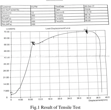
12mm diameter vizag tmt rod of 30 cm length is used for Tensile Strength Test. Test is done in Universal Testing Machine.
Fig.1 Result of Tensile Test
V.
ANALYSIS AND DESIGN OF
STRUCTURAL ELEMENTS
The modeling analysis is done in the STAAD.Pro
32
Copyright © 2018. IJEMR. All Rights Reserved.
ANALYSIS AND DESIGN CONSIDERING EARTH QUAKE
Earthquake forces are generated by the dynamic response of the building to earthquake induced ground motion. This makes earthquake actions fundamentally different from any other imposed loads.
Fig.3(A) Earthquake load
Fig.3(B) Earthquake load
ANALYSIS AND DESIGN CONSIDERING WIND LOAD
Wind is defined by its strength and direction of blowing. Sometimes because of unpredictable nature of wind it takes so devastating form during some Wind Storms that it can upset the internal ventilation system when it passes into the building.
Fig.4(A) Wind Load
Fig.4(B) Wind Load
LIVE LOAD AND DEAD LOAD
Live load is a civil engineering term that refers to a load that can change over time. The weight of the load is variable or shifts locations, such as when people are walking around in a building. Anything in a building that is not fixed to the structure can result in a live load, since it can be moved around. Dead loads are static forces that are relatively constant for an extended time. They can be in tension or compression.
Fig.5 Member Load
33
Copyright © 2018. IJEMR. All Rights Reserved.
Fig.7 Bending Z
Fig.8 Shear Y
Fig.9 (A) Steel Design Result
Fig.9 (B) Steel Design Result
Fig.10 Shear Bending
RESULTS AND DISCUSSION
0 10 20 30 40
-2 -4 -6 -8 -10 -15 -20 -30
N
O
O
F B
EA
M F
A
IL
LIVE LOAD IN KN/M2 FAILURE DUE TO LIVE LOAD
FAILURE DUE TO LIVE LOAD
0 20 40 60 80
1 2 3 5 7 10 15 20 30
N
O
O
F B
EA
N
F
A
IL
EARTH QUAKE LOAD
FAILURE DUE TO EARTH QUAKE
FAILURE DUE TO EARTH QUAKE
0 20 40 60 80
1 2 3 5 7 10 15 25
N
O
O
F B
EA
M F
A
IL
WIND LOAD
FAILURE DUE TO WIND LOAD
34
Copyright © 2018. IJEMR. All Rights Reserved.
VI.
CONCLUSION
It can be clearly observed that increase in live load, earth quake load and wind load causes failure of beams and columns in the structure. Up to -6 kn/m2 beams and columns resists the load (live). When it is -8 kn/m2, failure occurs in the structure. Like this due to increase in earthquake and wind load beams and columns fails in the structure.
REFERENCES
[1]Joseph, L.M., Poon, D., & Shieh, S. (2006). Ingredients of high-rise design: taipei 101, the world’s tallest building. Structure Magazine, 40-45.
[2] Ettouney, M. & Glover, N. (2002). Engineering of architectural systems. Journal of Architectural Engineering, 8(1), 7-9.
[3] Ettouney, M., Alampalli, S. & Agrawal, A. (2005). Theory of multihazards for bridge applications. Journal of Bridge Structures: Assessment, Design and Construction, Taylor & Francis, 1(3), 281-291.
[4] Duthinh, D. & Simiu, E. (2010). Safety of structures in strong winds and earthquakes: Multihazard considerations. Journal of Structural Engineering, 136(3), 330-333. [5] Crosti, C., Duthinh, D. & Simiu, E. (2011). Risk consistency and synergy in multihazard design. Journal of Structural Engineering, 137(8), 884-849.