Implementation of Low Frequency AC to High
Frequency AC with Single Stage ZVS-PWM Inverter
S.Arumugam1 S.Ramareddy2 M.Sridhar3
Research Scholar Professor, Professor &Dean
Bharath University, Chennai, India. Jerusalem College of Engg, Chennai. Bharath University, Chennai,
Abstract- This paper presents a novel soft-switching pulse width
modulation (PWM) utility frequency AC to high frequency (HF) AC power conversion circuit incorporating boost-active clamp single stage inverter topology. This power converter is more suitable and acceptable for cost effective HF consumer induction heating applications. Its operating principle is presented. The operating performances of this high frequency inverter using the latest insulated gate bipolar transistors are illustrated, which includes HFAC power regulation ranges and actual efficiency characteristics based on zero voltage soft switching operation ranges.. The simulation circuits are models are developed and they are simulated using ORCAD.
Keywords: Pulse Width Modulation, Boost active clamp bridge,
utility frequency, AC to high frequency (HF) AC power conversion, zero voltage Switching.
I. INTRODUCTION
I
n recent years, new application fields of high-frequency induction heating (IH) power technology in consumer and industry have developed more and more in all electricity power utilization systems as energy saving. For example, these IH appliances are IH cooking heater, IH rice cooker, IH hot water producer, IH steamer, and IH super heated steamer for cleaning, disinfecting, drying and cooking. These new IH applications in addition to microwave oven for food processor have been expanding dramatically with tremendous development of the core technology of the state-of-the art high-frequency power electronics in IH technology. However, application-specific high frequency resonant inverters used for these appliances cause switching losses and conduction losses of power devices, getting larger cooling devices and heat release systems, decreased rated ability of power devices by switching surges. Furthermore, increased EMI/RFI noise levels due to high frequency leakage current in high frequency switching of conventional high frequency inverters operated under hard switching PWM. With tremendous advances of power semiconductor. Switching devices, the electromagnetic induction eddy. Current based direct heat energy processing products and applications using high frequency power conversion circuits, inverters, cycloinverters and cyclo -converters have attracted. Special interest for consumer food cooking and processing. Appliances [1]– [3], [8]–[10]. Recently, cost effective induction Heating (IH) appliances usinghigh frequency inverters have been rapidly developed for utility frequency ac to high- frequency.ac power conversion system for consumer power and. energy applications. The equipments using high frequency. Inverter topologies have the practical advantages of safety. Cost effectiveness, energy saving, clean environment, high. Thermal conversion efficiency, rapid and direct focusing heating. Process, high power density, high reliability, environment. On-acoustic and low electromagnetic noise [4], [5]. These unique advantages are practically brought in accordance with Great progress of power semiconductor switching devices,. Digital and analogue control devices, circuit components and. high frequency soft switching inverters [6], [13], [14].Under the aforementioned technological situations, high frequency. Soft switching inverter topologies are indispensable for Consumer IH appliances.
These high frequency soft switching inverters must have the advantages of simple configuration. High efficiency, low cost and wide soft commutation operating. Ranges for high frequency operation [7], [12], [15]. The voltage source type soft-switching high frequency inverter using the latest insulated Gate bipolar transistors (IGBTs) and its modifications match the practical operating requirements mentioned previously. In this paper, a novel prototype of a boost-active clamp bridge single stage high frequency zero voltage soft-switching PWM inverter, which converts the utility frequency ac power into high frequency ac power with voltage boosting. This single stage high frequency inverter which is composed of single phase diode bridge rectifier, non-smoothing filter, boost-active clamp bridge type zero voltage soft switching PWM high frequency inverter, and induction heated load with planar type litz wire working coil assembly. Also we discussed in this paper in order to extend the soft switching operation ranges and to improve the power conversion efficiency. The aim is to control the output power for high temperature application including steel melting, brazing and hardening where the load parameters and frequency vary throughout the system operation. This paper is organized as follows.
II. PREVIOUSLY DEVELOPED ZVS–PWM HIGH FREQUENCY INVERTER
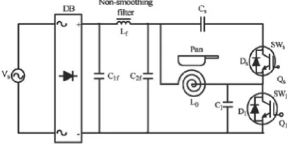
Fig. 1 shows a basic circuit configuration of the previously developed active voltage-clamped edge-resonant ZVS–PWM inverter, which can operate under the principle of ZVS–PWM or VPCF control strategy in order to solve harmful acoustic noise in multi-integrated inverter type IH cooking heater for multi -burners, in addition to harmonic current reduction in the utility ac power grid side. This voltage-fed ZVS–PWM high frequency inverter using the Q1, Qs, includes a VPCF function in the output load side and active power filtering function by connecting to a utility ac power grid interfaced single phase full-bridge diode rectifier with a non-smoothing dc filter. This high-frequency inverter is directly combined to the multi-integrated IH cooking heater with load pans and vessels, which are coupled to the ceramic spacer via two pancake-like heating working coils [11], [12].
Fig.1.
Previously developed HF inverter for IH cooker The resonant capacitor Csin series with the auxiliary active power switch Qs serves to clamp the resonant peak voltage across the main active power switch Q1. The non-conduction period of Q1 consists of two edge-resonant transition intervals during ZVS commutation operation and the auxiliary second resonant interval when voltage clamping with Qs and Cs.The heating output power of this high-frequency inverter (see Fig. 1) can be continuously adjusted by varying the operating period under the principle of ZVS and the variable power control strategy can be achieved at a fixed frequency by interpolating during the second resonance mode. Since the current in the first resonant capacitor C1 is generated only during switch transition, the current flowing through the voltage-clamping capacitor Cs is generated only during the clamping mode or conduction mode of Qs and capacitors with a low current rating can be used in this case.
III. NEWLY PROPOSED BOOST-ACTIVE CLAMP HIGH FREQUENCY INVERTER
A. Main Circuit Configuration
Fig. 2. Single stage soft-switching PWM HF inverter
448.1e
2 2 L1 D4
D5 D8 1 2 M1 C2
25u
1N4500 1N4500 .1u
1 1 MUR150
V3 IRF840 V1 = 0 V2 = 10v
V5 TD = 0
VOFF = 0 V1 = 0v V2M3 TR = 1ns
VAMPL = 220v V2 = 10v C1TF = 1ns
FREQ = 50hz C6TD = 0
.01u
PW = 10u L2
.1u
TR = 1ns IRF840 PER = 20u 1 2
TF = 1ns
50u PW = 10u
PER = 20u
R5
V+
0
C5
2 2
200
D6 D7 M2 0.1u
V4 1N4500 1N4500
V1 = 0 IRF840
1 1 V2 = 10v
TD = 10us C4
V-TR = 1ns
.1u TF = 1ns
PW = 10u
PER = 20u
Fig.3.Proposed circuit model for IH Application
The IH load circuit of this inverter consists of the working coil composed of litz wire and IH metal-based object (pan or vessel) represented by the transformer equivalent circuit model (Load time constant T=L2/R2 [R2: Equivalent effective resistance due to a frequency dependent skin effect of the heated material itself,L 2: the eddy current induced side self inductance]. Where L1 is the self -inductance of the working coil, with loosely-coupled mutual inductance M.
B. High Frequency AC Power Control Scheme
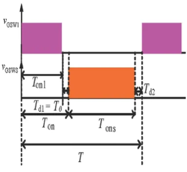
Fig. 4. Schematic PWM gate pulse timing sequences
The high frequency ac output power of the proposed inverter circuit, which is delivered to the IH load as IH cooking heater, can be continuously regulated by a constant frequency asymmetrical PWM control scheme under a condition ZVS. The gate voltage pulses timing signals sequences for Q1, Qsand are shown schematically in Fig. 4.Q1 is first switched on during a period Ton1and before Q1is turned off by a time of T0. Then Q s, is turned on after turning off Q1by a dead time of Td1. Q1 is again switched on after a dead time Td2as another period starts as depicted in Fig. 4. This high frequency inverter has equal dead time (td1=Td2)control scheme. The constant frequency asymmetrical PWM duty cycle is the ratio of conduction time Ton of Q1to total switching period T. As a control variable, the duty cycle is defined as
Ton1+T0
D = --- --- (1) T
By varying the PWM duty cycle as a control variable, the High-frequency ac output power of this soft-switching inverter can be regulated continuously.
C. Operation Switching States and Equivalent Circuits
The operation states of the proposed single stage high frequency power converter during one switching cycle. The corresponding state equivalent circuits are represented in Fig. 5. The operation states are divided into six operating states during one switching period, which can be simply explained in the following.
State 1 (SW: ON, : OFF, SW : OFF and : OFF) This switching state equivalent circuit is shown in Fig. 5(a). In this operating state, two current loops in the equivalent circuit are formed. The magnetic energy is stored into the boost inductor through the loop of C2f-Lb-Q1-C2f and the input power is delivered to the induction-heated load through Cb-L0-Q1-Cb.
State 2 (SW : OFF, : OFF, SW : OFF and : OFF) The equivalent circuit of state 2 is depicted in Fig. 5(b). In state 2, the resonant energy is stored into through the two composed loops of Lb-C1 -Cb-C2f-LbandL0-C1-L0.
State 3 (SW : OFF, : OFF, SW : OFF and : ON) The energy is stored into through the loop formed byLb-Cs-Cb- C2f -Lb and the energy is delivered to the IH load through the composed loop of Ds-Cs-C2f-Lb. The equivalent circuit of state 3 is shown in Fig. 5(c).
State 4 (SW : OFF, : OFF, SW : ON and : OFF) The equivalent circuit of state 4 is depicted in Fig. 5(d) In this state, the energy is delivered to the IH load through the composed loop of Cs-Qs-L0-Csand the energy is stored into capacitor through the composed loop of Lb-L0-Cb-C2f.
State 5 (SW : OFF, : OFF, SW : OFF and : OFF) This equivalent circuit of state 5 is delineated in Fig. 5(e). During this operating state, the energy is transferred to the IH load-working coil L0through the composed loop of L0-C1-L0and the energy is stored into capacitor through the composed loop of Lb-L0-Cb-C2fas in state 4.
IV.SIMULATION RESULTS
VOFF = 0 VAMPL = 220v FREQ = 50hz
V1 V+
R1
1k
V
-0
Fig.5.1.circuit to measure input voltage
Fig.6.1. Boost circuit & half bridge inverter circuit
VOFF = 0 VAMPL = 220v FREQ = 50hz
V1
Fig5.2.Input voltage
2
2
D4 D1
1 1N4500 1N4500
1
V+
R1 1k
V-1.560e-18V
2 2
D2 D3
0 1 1N4500 1 1N4500
Fig5.3.Cirruit for rectifier
Fig.6.2.Boost circuit & half bridge invertervoltages
Fig.6.3. circuit with addition of resonant circuit
Fig.7.1. Proposed circuit model for Induction Heating
Fig.7.2.output voltages for Induction Heating
Fig7.3.Enlarged output voltages
Single stage zvs-pwm High frequency inverter system is simulated and the results are presented here. Fig.5.1. and Fig.5.3 shows to measure circuit input voltages and Rectifier output voltages. Scopes are connected to measure input and
output voltages. It’s corresponding input and output voltages
are presented in Fig.5.2 and Fig.5.4.respectively. Boost
circuit & half bridge inverter circuit is as shown in Fig.6.1. and it’s
output voltage is shown in Fig.6.2.Inverter circuit with addition of resonant circuit as shown in Fig.6.3.and its output is as shown in Fig.6.4. Proposed circuit model for Induction Heating is as shown in Fig 7.1. The required induction heating voltages are obtained and presented in Fig.7.2. Enlarged output PAN (IH) voltages are shown in Fig.7.3. In order to achieve unity power factor at the utility side and pure non-smoothing dc current at inverter side, we designed optimum value of filter parameters.
V. CONCLUSION
In this paper, a novel circuit topology of utility frequency ac to high frequency ac power converter employing boost active-clamped single stage ZVS–PWM high frequency inverter has been proposed for consumer induction heating appliances such as IH cooking heater, IH steamer, IH super heated steamer, IH fixing roller and IH far-infrared griddle. The new single stage high frequency IH inverter using boosted voltage function can eliminate the dc and low frequency components of the working coil current and reduce the power dissipation of the circuit components and switching devices. The operating principle of this high frequency inverter, the operation modes have been presented and discussed on the basis of simulation results. The simulation results are in line with the predictions. This work deals with simulation studies. Hardware implementation is not in the scope of this work.
For future work, the boost active-clamped bridge single stage high frequency power converter using the promising power switching devices ESBTs, SiC–SBDs, and SiC–MOSFETs will be evaluated and discussed in order to achieve much higher the overall power conversion efficiency and high power density REFERENCES
[14] A. Okuno, H. Kawano, J. Sun, M. Kurokawa, A. Kojina, and
M. Nakaoka, “Feasible development of soft-switched SIT inverter
with load-adaptive frequency- tracking control scheme for induction heating,”IEEE Trans. Ind. Appl., vol. 34, no. 4, pp. 713–
718, Jul./Aug. 1998.
[2] S. Hishikawa, M. Serguei, M. Nakaoka, I. Hirota, H. Omori,
and H. Terai, “New circuit topology of soft switching single-ended
high frequency inverter using IGBTs,” IEICE-J Energy Electron.
Prof Meeting, vol. 100, no. 628, pp. 19–24, Feb. 2000.
[3] M. Kaneda, H. Tanaka, and M. Nakaoka, “A novel prototype
of single-ended push-pull soft-switching high- frequency inverter using a single auxiliary ZVS-PWM switch,” IEICE-J. Energy Electron. Prof.Meeting, vol. 100, no. 628, pp. 31–37, Feb. 2000.
[4] H. Sadakata, H. Terai, H. Omori, H. Yamasita, and M.
Nakaoka, “The development of ZCS-PWM-SEPP inverter with
[5] H. Sugimura, N. A. Ahmed, T. Ahmed, H. W. Lee, and
M. Nakaoka, “Utility ac frequency to high frequency ac power conversion circuit with soft switching PWM strategy,” KIEE Int. Trans. Elect. Mach. Energ Conv. Syst., vol. 5-B,
no. 2, pp. 181–188, 2005.
[6] B. Saha, S. K. Kwon, H. Omori, H. W. Lee, and M.
Nakaoka, “A Novel utility frequency ac to high frequency ac
power converter with boosted half-bridge single stage circuit
arrangement,” inProc. Int. Conf. Elect. Mach. Syst. (ICEMS),
Nagashaki, Japan, Nov. 2006, [CD ROM].
[7]H. Kifune, Y. Hatanaka, and M. Nakaoka, “Cost effective
phase shifted pulse modulation soft switching high frequency
inverter for induction heating applications,”Proc. Inst. Elect. Eng. , vol. 151, no. 1, pp. 19–25, Jan. 2004.
[8] K. Ogura, L. Gamage, T. Ahmed, M. Nakaoka, I. Hirota,
H. Yamashita, and H. Omori, “Performance evaluation of
edge-resonant
ZVS-PWM high-frequency inverter using trench-gate IGBTs
for consumer induction cooking heater,” Proc. Inst. Elect. Eng., vol. 151, no. 5, pp. 563–568, Sep. 2004.
[9] H. Fujita, H. Akagi, K. Sano, K. Mita, and R. H. Leonard,
“Pulse density modulation based power control of a 4 kW
400 kHz voltage-source inverter for induction heating
applications,” inProc. IEEJ PCC, Yokohama, Japan, 1993,
pp. 111–116.
[10] J. Acero, R. Alonso, J. M. Burdío, and L. A. Barragán,
“Modeling of planar spiral inductors between two multilayer
media for induction heating applications,”IEEE Trans.
Magn., vol. 42, no. 11, pp. 3719–3729, Nov. 2006.
[11]W. F. Peschel, “Load power matchingof high-frequency
power supplies for induction heating,” IEEE Trans. Ind.
Appl., vol. IA-10, no. 3, pp. 351–359, May/Jun. 1974. [12] J. Acero, R. Alonso, J. M. Burdío, L. A. Barragán, and
D. Puyal, “Frequency- dependent resistance in litz-wire
planar windings for domestic induction heating appliances,” IEEE Trans. Power Electron., vol. 21 no. 4, pp. 856–866, Jul. 2006.
[13 J. M. Burdío, F. Monterde, J. R. García, L. A. Barragán,
and A. Martínez, “A two- output series-resonant inverter for
induction-heating cooking appliances,” IEEE Trans. Power Electron., vol. 20, no. 4, pp. 815–822, Jul. 2005.
[14]N. J. Park, D. Y. Lee, and D. S. Hyun, “A power-control scheme with constant switching frequency in class-D inverter for induction-heating jar application,”IEEE Trans. Ind. Electron., vol.
54, no. 3, pp. 1252–1260, Jun. 2007.
[15] B. Saha, K. Y. Suh, S. K. Kwon, T. Mishima, and M.
Nakaoka, “Selective dual duty cycle controlled high frequency
inverter using a resonant capacitor in parallel with an auxiliary reverse blocking switch,”J. Power Electron.,
vol. 7, no. 2, pp. 118–123, Apr. 2007. About Authors
S. Arumugam has obtained his B.E degree from Bangalore University, Bangalore in the year 1999. He obtained his M.E degree from Sathyabama University, Chennai in the year 2005.He is presently a research scholar at Bharath University, Chennai. He is working in the area of Resonant inverter
fed Induction Heating. He has published more than 10 international journals. Presently he is working as a Assistant Professor in Electrical and Electronics Engg department at Ganadipathy Tulsis jain Engineering college, Vellore, Tamilnadu. He has published books on Basic Electrical Engg and Electrical machines.
S.Ramareddy is Professor of Electrical Department, Jerusalem Engineering College, Chennai. He obtained his D.E.E from S.M.V.M Polytechnic, Tanuku, A.P. A.M.I.E in Electrical Engg from institution of Engineers (India), M.E in Power System from Anna University.
He received Ph.D degree in the area of Resonant Converters from College of Engineering, Anna University, Chennai. He has published over 20 Technical papers in National and International Conference proceeding/Journals. He has secured A.M.I.E Institution Gold medal for obtaining higher marks. He has secured AIMO best project award. He has worked in Tata Consulting Engineers, Bangalore and Anna University, Chennai. His research interest is in the area of resonant converter, VLSI and Solid State drives. He is a life member of Institution of Engineers (India), Indian Society for India and Society of Power Engineers. He has published books on Power Electronics and Solid State circuits.