U N I V A C® F I
L E- COM PUT E R
PREFACE
This publication is a summary of the functional and physical characteristics of the Univac
Fi Ie-Computer System. Jts purpose is to provide company personnel with basic information on
the Univac File-Computer until detailed programming, installation, and maintenance manuals
are published. This summary describes the Univac File-Computer Model 0 and Modell as well
as Univac Fi Ie-Computer input-output units.
These input-output units include punched-card, magnetic tape, paper taoe, keyboard, line
printer and special-purpose devices.
TABLE
OFCONTENTS
PAGE
INTRODUCTION.... . . . . .. . . . .. .. . . . . . . .. . . . .
iii
UNIVAC FILE-COMPUTER CENTRAL COMPUTERS. . .
1
UNIVAC FILE-COMPUTER GENERAL STORAGE SYSTEMS. . .
11
UNIVAC FILE-COMPUTER MODEL I CONSOLE SYSTEM. . .
16
UNIVAC FILE-COMPUTER INQUIRY TYPEWRITER. . .
19
UNIVAC FILE-COMPUTER 90-COLUMN CARD SYSTEM
23
UNIVAC FILE-COMPUTER 90-COLUMN CARD SYSTEM (WITH POST-READ CHECKING) . . .27
UNIVAC FILE-COMPUTER SO-COLUMN CARD SYSTEM (BULL) . . .
32
UN I V A C F I L E -C 0 M PUT ERMA G NET I C TAP E UN IT. . .
38
UNIVAC FILE-COMPUTER SORT-COLLATE SYSTEM. . .
46
I ntroducti on
A Univac Fi Ie-Computer System is an electronic data-process ing system which features
the simultaneous operation of:
a Central (general-purpose) Computer;
a large-capacity, random-access, magnetic drum memory called General Storage; and
an integrated system of Univac File-Computer Input/Output Units and other
auxilia-ry devices.
Time-shared (simultaneous) operation is possible because
the Central Computer, its associated General Storage; and each of the Univac
File-Computer Input/Output Units operate independently under control of a computer
program;
instructions or sub- instructions can be programmed to define a time-shared
oper-ation for General Storage or one of the Univac File-Computer Input/Output Units; and
the defined operation can be initiated without causing subsequent delay to the
computer's execution of logical and arithmetic operations.
Once initiated, a time-shared General Storage or Univac File-Computer Input/Output Unit
operation is carried out independently of the Center Computer. It is, therefore, not
un-common in the execution of Univac File-Computer System programs for
The Central Computer to be executing an arithmetic or logical operation, General
Storage to be engaged in a reading or recording operation, and a variety (perhaps
all) of the Univac Fi Ie-Computer Input/Output Units to be operating.
Two types of Univac File-Computer Systems are available: Model 0 and ModelL These
systems differ, as explained in Sections 1 and 2, in both the Central Computer and General
Storage which they include. However, any Univac File-Computer Input/Output Unit
(ex-cept the Univac File-Computer Modell Console System), can be in either system. Up to
8 Univac File-Computer Input/Output Units, in any combination, can be simultaneously
controlled in Model 0 Systems. Modell Systems can control up to 10 Univac F
ile-Com-puter Input/Output Units, in any combination.
SECTION
1
UNIVAC FILE-COMPUTER CENTRAL COMPUTERS
Both the MO<fel 0 and Model 1 Central Computers are general-purpose, serial, three-ad-dress, digital machines, equipped with their own operating storag~. Their basic unit of data ts an alphanumeric character expressed in Univac code (excess-three, binary coded decimal notation). In both computers, t~ standard word length manipulated in an arith-metic operation is 12 characters: 11 characters plus a sign character. Aritharith-metic oper-ations are automatically checked, and the accuracy of data transmission within, as well
as to and from, each machine is also automatically verified by checking a (redundant) parity-bit stored with each Univac-coded character.
MODEL 0
The Model 0 Central Computer is a plugboard machine. Patchcord wiring on a removable
connection panel (plugboard) is used to define all of its instructions and sub-instructions; and the order, or sequence, in which these instructions and sub- instructions are to be carried out. Model 0 instructions are called Program Steps; sub- instructions are called
Sub-Steps.
FUNCTIONAL DESCRIPTION
Program. A Model 0 computer program is a series of plugboard defined Program Steps
each of which, in addition to defining a computer instruction, also defines the location of the next computer instruction, and/or one of more Sub-Steps.
Each Program Step consists of five basic elements:
1. The arithmetic or operational process to be performed:
Transfer
Masking Transfer Left Zero Elimination
Add
Subtract
,
Multiply Divide
Compare
Channel Search Equal
2. The storage location of the first value (VI) upon which the process is to oper-ate; and the number of places, if any, that value is to be shifted prior to its use in the process.
3. The storage location of the second value (V2) upon which the process isto operate; and the number of places, if any, that value is to be shifted prior to its use in the process.
4. The storage location to which the result of the program (R) is to be delivered;
and the number of places, if any, the result is to be shifted prior to its storage.
5. The particular Plugboard Step (one of 48 numbered 57-98) where the next
Pro-gra!" Step is located; and/or the Sub-Steps) to be initiated as the program passes to the next instruction. The following Sub-Steps are available:
,
Program Se I ect Write Unit Record Read Unit Record
Demand In (0-7)
Demand T est In <0-7) Branching
Function Delay
Function Sequence
Storage. The main operating storage of the Model 0 Central Computer is a High-Speed Magnetic Drum. Up to 13 drum tracks (120 characters per track) are used:
5 tracks for Factor or Intermediate Storage.
1 up to 8 tracks for InpuVOutput operations: one for each InpuVOutput Unit used.
A revolver in General Storage is also part of the operating memory of the Model 0 Central Computer. This revolver functions as a temporary storage for data transmissions to and
from the computer and General Storage. The revolver stores a Unit Record. Up to twenty fields, FO- F19, (each 12 characters or less) can be referred to by the computer in any General Storage operation. Those fields are defined by patchcord-wiring on the General
Storage Plugboard.
Input-Output System. The Model 0 Central Computer in-out system includes circuitry
in both the computer and each Univac File-Computer InpuVOutput Unit employed. The computer circuits are those required for the execution of Demand Test In and Demand In
sub-instruction sequences. The Univac File-Computer InpuVOutput Unit's in-out circuits
are all logically identical, and are cal led Demand Stations.
When a Univac File-Computer InpuVOutput Unit is physically connected to the Computer,
(0-7) in the computer. Any Univac File-Computer InpuVOutput Unit can be plugged into any Demand Station position. Once plugged, however, it is designated as
VO
Unit "n" (where n = 0-7), and it communicates only with a correspondingly numbered I/O Track(00-07) on the High-Speed Drum.
Each Univac File-Computer InpuVOutput Unit Demand Station enables the 'computer to
test the status of the Unit
at
any time to determine whether the Unit is READY or NOT READY for subsequent use. A Univac File-Computer InpuVOutpu:t Unit is READY if itis operable and not engaged in a previously-initiated operation. It is NOT READY in all other cases. By executing the appropriate Demand Test In (0-7) sub-instruction, the
puter can resume its internal computing without delay. If the Unit is READY, the com-puter can execute an appropriate Demand IN (0-7) sub- instruction. This sub- instruction can Ca) give the Univac File-Computer klpuVOutput Unit an operation to perform, or (b)
receive (program variance) control information from the Univac File!.Computer InpuVOut-put Unit, or in special cases, perform (a) and (b). In any case, no delay is introduced into central computer operation.
If a Unit is given an operation to perform, it places itself in a NOT READY status, and begins the defined operation. When a Univac File-Cor11Juter InpuVOutput Unit is in a NOT READY condition, it can carry out data transmission to and from its associated I/O Track as required in the operation specified by the computer program. When a Univac
Fi Ie- Computer Input/Output Unit completes the required operation, it places itself in a
READY condition. The I/O Track is then connected to the computer, and is no longer available to the Unit. The computer and Univac File-Computer InpuVOutput Unit thus
alternately share control of the Unit's I/O Track, depending on whether the Unit is in a READY or NOT READY status, respectively.
PHYSICAL. DESCRIPTION
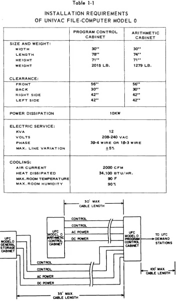
The Model 0 Central Computer (Figures 1-1 and 1-2) consists of two cabinets: Program Control and Arithmetic. Table 1-1 lists the Model 0 installation requirements; Figure 1-3 gives cabl ing information.
Figure J-J.
Model 0 Program
Control Cabinet
Figure 1-2. Model 0
Table 1-1
INSTALLATION REQUIREMENTS OF UNIVAC FILE-COMPUTER MODEL 0
PROGRAM CONTROL ARITHMETIC
CABINET CABINET
SIZE AND WEIGHT:
WIDTH 30" 30"
LENGTH 78" 74"
HEIGHT 71" 71"
WEIGHT 2015 LB. 1279 LB.
CLEARANCE:
FRONT 56" 56"
BACK 30" 30"
RIGHT SIDE 42" 42"
LEFT SIDE 42" 42"
POWER DISSIPATION 10KW
ELECTRIC SERVICE:
KVA 12
VOLTS 208-240 VAC
PHASE 3~4 WIRE OR 10-3 WIRE MAX. LINE VARIATION ±5%
COOLING: UFC MODEL 0 GENERAL STORAGE CABINET
AIR CURRENT 2000 CFM HEAT DISSIPATED 34,100 BTU/HR. MAX. ROOM TEMPERATURE 90F
MAX. ROOM HUMIDITY 90%
CONTROL
UFC AC POWER
MODEL 0 ~~::...:...=.::...:..---t CONTROL I-....;D:;.;C~POW:;.;.;.;E;.;.R~ _ _ --t
CABINET
-rI'\, II~'"
IV v'''''
DEMAND
STATIONS
CONTROL~ _ _ _ _ _ _ - ;
CONTROL=--_ _ _ _ _ _ -f t - - - - '
h
100' MAX.I
CABLE LENGTH--;
AC POWE::.:R _ _ _ _ _ _ - ; t----~
DC POWE::..R=---_ _ _ _ _ --t t - - - . . J 35' MAX.
CABLE LENGTH
MODEL 1
The Modell Central Computer is designed for operation as
(a) a plugboard computer;
(b) an internally-stored-program computer; or as
(c) a combination plugboard/internally-stored-program computer.
FUNCTIONAL DESCRIPTION
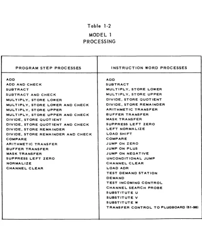
Plugboard OpE;!'~Uon. When operated as a plugboard computer, Modell executes pro-gram Steps and Sub-Steps which are defined and carried out in much the same manner as
those in the Model
0
Central Computer. However, as noted in Tables 1-2, 1-3, and 1-4, respectively, different processes and Sub-Steps are available and the operating storage for the Central Computer has a larger capacity.Internallx-Stored~Program Op~raUQD. When operated as an internally-stored-program computer, Modell executes Instruction Words. An Instruction Word is a 12-character
com-puter instruction which is stored in the operating memory of the comcom-puter, generally in sequence with other instruction Words on the High-Speed Drum. An Instruction Word has the following format:
U
v
W
OPxxx
xxx xxx xxx (x represents one characterjwhere U,
V,
and Ware usually storage addresses forVI, V2,
andR
respectively; and OP is an operation code which spec ifies what the computer is to do in executing theinstruc-tion. When the Model 1 is used only as an internally-stored-program computet, the left
two characters of OP specify one of the first 26 processes listed under Instruction Word Processes in Table 1-2. The right-most character in OP is a special character which
ex-tends or modifies the process specified by the other characters in OP. This special character has various values and is used to initiate the Instruction Word Sub-Instructions listed in Table 1-3. The storage location from which each Instruction Word is obtained is
given by a Program Address Counter that is used to seauence internally stored programs.
Combination Plugboard/lnternally-Stored-Program Operation. When Modell is used as a combination plugboard/internally-stored-program computer, it executes Program Steps or
Instruction Words depending on whether Program Control obtains its instruction from the plugboard or the internally-stored program, respectively. Control is transferred from the
internal program to the plugboard by executing a Transfer Control Instruction Word. The
Program Steps defined on the plugboard are executed rather than Instruction Words.
Transfer of control from the plugboard to the internally-stored program is achieved by
executing a NEXT INSTRUCTION Sub-Step on the plugboard. When this Sub-Step is carried out, plugboard-defined operations stop, and the next instruction executed is an Instruction Word. This Instruction Word's location is specified by the Program Address Counter.
Table 1-2
MODEL 1 PROCESSING
PROGRAM STEP PROCESSES
ADD
ADD AND CHECK SUBTRACT
SUBTRACT AND CHECK MULTIPLY, STORE LOWER
MULTIPLY, STORE LOWER AND CHECK MUL T IPLY, STORE UPPER
MULTIPLY, STORE UPPER AND CHECK DIVIDE, STORE QUOTIENT
DIVIDE, STORE QUOTIENT AND CHECK DIVIDE, STORE REMAINDER
DIVIDE, STORE REMAINDER AND CHECK COMPARE
ARITHMETIC TRANSFER BUFFER TRANSFER MASK TRANSFER SUPPRESS LEFT ZERO NORMALIZE
CHANNEL CLEAR
INSTRUCTION WORD PROCESSES
ADD SUBTRACT
MULTIPLY, STORE LOWER MULTIPLY, STORE UPPER DIVIDE, STORE QUOT lENT DIVIDE, STORE REMAINDER ARITHMETIC TRANSFER BUFFER TRANSFER MASK TRANSFER SUPPRESS LEFT ZERO LEFT NORMALIZE LOAD SHIFT COMPARE JUMP ON ZERO JUMP ON PLUS JUMP ON NEGATIVE UNCONDITIONAL JUMP CHANNEL CLEAR
LOAD ADR
TEST DEMAND STATION DEMAND
TEST INCOMING CONTROL CHANNEL SEARCH PROBE SUBSTITUTE U
SUBSTITUTE V SUBSTITUTE W
Table 1-3
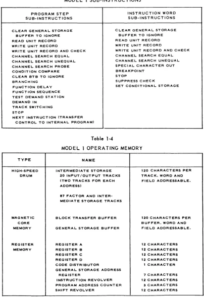
MODEL 1 SUB-INSTRUCTIONS
PROGRAM STEP SUB-INSTRUCTIONS
INSTRUCTION WORD SUB-INSTRUCTIONS
CLEAR GENERAL STORAGE C LEAR GENERAL STORAGE BUFFER TO IGNORE
READ UNIT RECORD WRITE UNIT RECORD
BUFFER TO IGNORE READ UNIT RECORD WRITE UNIT RECORD WRITE UNIT RECORD AND CHECK
CHANNEL SEARCH EQUAL CHANNEL SEARCH UNEQUAL CHANNEL SEARCH PROBE CONDITION COMPARE
WRITE UNIT RECORD AND CHECK CHANNEL SEARCH EQUAL CHANNEL SEARCH UNEQUAL SPECIAL CHARACTER OUT BREAKPOINT
STOP CLEAR BTB TO IGNORE
BRANCHING SUPPRESS CHECK
FUNCTION DELAY SET CONDITIONAL STORAGE FUNCT ION SEQUENCE
TEST DEMAND STATION DEMAND IN
TRACK SWITCHING STOP
NEXT INSTRUCTION (TRANSFER CONTROL TO INTERNAL PROGRAM)
Table 1-4
MODEL 1 OPERATING MEMORY
TYPE HIGH-SPEED DRUM MAGNETIC CORE MEMORY REGISTER MEMORY NAME
INTERMEDIATE STORAGE 20 INPUT/OUTPUT TRACKS (TWO TRACKS FOR EACH ADDRESS)
87 FACTOR AND INTER-MEDIATE STORAGE TRACKS
BLOCK TRANSFER BUFFER GENERAL STORAGE BUFFER
REGISTER A REGISTER B REGISTER C REGISTER D
CODE DISTRIBUTOR
GENERAL STORAGE ADDRESS REGISTER
INSTRUCTION REVOLVER PROGRAM ADDRESS COUNTER SHIFT REVOLVER
120 CHARACTERS PER TRACK. WORD AND FIELD ADDRESSABLE.
120 CHARACTERS PER BUFFER. WORD AND FIELD ADDRESSABLE.
Storage. The type, name, and capacity of each part of the operating storage in Model 1
Central Computers is I isted in Table 1-4.
All locations in operating storage can be referred to by the U,
V,
and W portions of In-structions Words. Only the ten (pairs of) InpuVOutput Tracks (00-09) and the Factor Storage Tracks (11-12) are directly available to Program Steps via the plugboard address-ing system. Program Steps in sequences initiated by Transfer Control Instruction Words,however, can access any track on the High-Speed Drum if the
VI, V2,
or R ADDRESS hubs are appropriately patched.All Model 1 General Storage Operations can be time-shared with the operation of the Central Computer. (See Section 2)
Input-Output System. The Model 1 Central Computer's in-out system is identical to that in the Model 0 Central Computer except that (a) each
110
Track location is actuallya pair of tracks, and (b) up to 10 Univac File-Computer InpuVOutput Units can be in-cluded. In Model 1, at any given time at any of the 10 I/O Track locations, the computer
is connected to one track of the pair, and the Univac File-Computer InpuVOutput Unit is connected to the other track of the pair. The computer and Univac File-Computer InpuV Output Unit can thus time-share operations at the same I/O Track location. While the Univac File-Computer InpuVOutput Unit is loading or unloading one track, the computer
can be loading or unloading the other. Track switching circuity in the Univac File-Com-puter InpuVOutput Unit can be operated by the comFile-Com-puter program to reverse the track assignments: the track formerly connected to the computer can be made available to the
Univac File-Computer InpuVOutput Unit; and, what was the Univac File-Computer InpuV Output Unit's track, can be made available to the computer. When the computer refers
to an I/O Track location, it always communicates with the track (of the pair) to which it
is connected at that time. When data transmissions to and/or from a Univac File-Computer
InpuVOutput Unit occur, they take place to and/or from the track to which the Univac
File-CorT1>uter InpuVOutput Unit is connected at that time. All data transmissions to and from each Univac File-Computer InpuVOutput Unit take place independently of the Central Computer.
PHYSICAL DESCRI PTION
The Model 1 Central Computer (Figures 1-4, 1-5 and 1-6) consists of three cabinets:
Modell Program Control 1 Cabinet Modell Program Control 2 Cabinet
Table 1-5
TENTATIVE INSTALLATION REQUIREMENTS OF UNIVAC FILE-COMPUTER MODEL 1
PROGRAM PROGRAM
ARITHMETIC CONTROL CONTROL
CABINET CABINET 1t1 CABINET !t2
SIZE AND WEIGHT:
WIDTH 30" 30" 30"
LENGTH 80" 80" 80"
HEIGHT 71" 71" 71"
WEIGHT 2000 LB. 2000 LB. 1420 LB.
CLEARANCE:
FRONT 56" 56" 56"
BACK 30" 30" 30"
RIGHT SIDE 42" 42" 42" LEFT SIDE 42" 42" 42"
POWER DISSIPATION: 15.5 KW
ELECTRIC SERVICE:
KVA 20
VOLTS 208-240 VAC
PHASE 3f)-4w1RE OR 1t)-3wIRE
MAX. LINE VARIATION +
-
5"1.COOLING:
AIR CURRENT 3000 CFM
HEAT DISSIPATED 53,000 BTU/HR.
MAX. ROOM TEMPERATURE 90F
GENERAL STORAGE CABINET
CQIITROL CQIITROl.
Figure 1-6. Model 1 Arithmetic Cabinet
ARITH-ME Tie
CABINET CONTROl. CONTROl. CONTROL. POWER
L 30'MAX !CABLE LENGT
100' MAX CABLE LENGTH.
SERVICE VOLTAGE
PROffiAM CONTROL CABINET
100' MAX
CABLE LENGTH
CONTROL POWER POWER
L
30' MAX1-
CABLE LENGTHSERVICE VOLTAGE
PROGRAM
CONTROl. CABINET
2
TO UFC DEMANO STATIONS
L IOO'MAX J , . CABl.E . ,
LENGTH
SECTION
2
UNIVAC FILE-COMPUTER GENERAL STORAGE SYSTEMS
FUNCTIONAL DESCRIPTION
Although the Model 0 and Model 1 General Storage Systems are radically different in
certain respects, they have the following common design features:
1. A format for storing data which is similar (and, in many cases, identical> to the
form of the business transaction. Thi·s basic, typical format is the individual
Unit Record.
2. A capacity for storing internally thousands of Unit Records; the number of Unit
Records and the length of each Unit Record being flexible, and determined by
individual application requirements.
3. A random-access storage feature which permits either Univac File-Computer
System to keep a current balance for a large number of items with high volume
activity. Specifically, it allows
entry of input data into General Storage in the random sequence of its arrival;
and
random-access to any Unit Record stored in General Storage either to obtain
data from that Unit Record or to selectively alter data in that Unit Record.
4. A Search feature which enables General Storage to look for a certain Unit Record
in accordance with a key or identifier, even though that Unit Record's address is
not known.
5. Simultaneous operation with the Central Computer. Once given a time-sharing
oper-ation to perform, each type of General Storage carries that operoper-ation out
inde-pendently of the Central Computer.
PHYSICAL DESCRIPTION
The Model 0 General Storage System (Figures 2-1 and 2-2) consists of two cabinets:
General Storage and General Storage Extension. Table 2-2 lists the Model 0 General
Storage System installation requirements. Figure 2-3 is the cabling diagram for the Model
o
General Storage System.The Model 1 General Storage System (Figures 2-4 and 2-5) consists of two cabinets
General Storage Control and General Storage Drum. Table 2- 3 I ists the tentative Modell
General Storage installation requirements. Figures 2-6 is the cabl ing diagram for the Model
1
General Storage System.Table 2-1
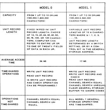
MODEL 0 AND MODEL 1 GENERAL STORAGE SYSTEMS
MODEL 0 MODEL 1
CAPACITY FROM 1 UP TO 10 DRUMS FROM 1 UP TO 33 DRUMS (180,000-1,800,000 (180,000-5,940,000 CHARACTERS) CHARACTERS)
UNIT RECORD FIXED (WIRED-IN) UNIT VARIABLE UNIT RECORD
LENGTH RECORD LE,NGT H. CHOICE LENGTHS OF 12 N CHARAC-OF 12,15,20,24,30,40,50, TERS WHERE N = " 2, 3, 60,75, 100, OR 120 C HARAC- • . • 10.
TERS. COMPUTER CAN UNIT RECORD LENGTH REFER TO ENTIRE UR OR DETERMINED BY A SWITCH TO ONE OF TWENTY FIELDS SETT I NG, OR BY A CON-OF DATA IN EACH UR, TROL BIT IN THE GENERAL
STORAGE ADDRESS.
AVERAGE ACCESS
34 MS 17 MS
TIME
TIME-SHARED WRITE UNIT RECORD WRITE UNIT RECORD
OPERATIONS WRITE UNIT RECORD AND
READ UNIT RECORD
CHECK
(A WRITE UNIT RECORD READ UNIT RECORD AND CHEC K OPERAT ION CHANNEL SEARCH EQUAL CAN BE PROGRAMMED.) CHANNEL SEARCH UNEQUA
CLEAR GENERAL STORAGE BUFFER TO IGNORE CODES
OPERATIONS CHANNEL SEARCH EQUAL ALL MODEL 1 GENERAL
NOT CHANNEL SEARCH UN- STORAGE OPERAT IONS
Figure 2-2. Model 0 General Storage Cabinet Model 0 General Storage Extension Cabinet
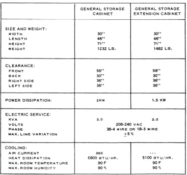
Table 2-2
INSTALLATION REQUIREMENTS
OF UNIVAC FILE-COMPUTER MODEL 0 GENERAL STORAGE SYSTEM
I
GENERAL STORAGE GENERAL STORAGE CABINET EXTENSION CABINET
SIZE AND WEIGHT:
WIDTH 30" 30"
LENGTH 46" 46"
HEIGHT 71" 71"
WEIGHT 1232 LB. 1482 LB.
CLEARANCE:
FRONT 56" 56"
BACK 30" 30"
RIGHT SIDE 36" 36"
LEFT SIDE 36" 36"
POWER DISSIPATION: 2KW 1.5 KW
ELECTRIC SERVICE:
KVA 3.0 2.0
VOLTS 208-240 VAC
PHASE 3,0-4 W IR E OR 10-3 WIRE
MAX. LINE VARIATION +5%
COOLING:
AIR CURRENT 360
--
-HEAT DISSIPATION E800 BT U/ HR. 5100 BTU/HR.
MAX. ROOM TEMPERATURE 90 F 90 F
GENERAL STORAGE EXTENSION
CAB INET 2
-~
30' ... x
CABLE LENGTH
CONTROL INTERLOCK
r-
lO' ... X-1
CABLE LENGTH CQNGENERAL
TRO rC~O~N~T~R~O~L ________ ~
STORAGE INTE
EXTENS ION CABINET
I
30'
CABLE
MAX
~
LENGTH
G ENE R A L !-,C:....:O:,.:.N:,..;T..,;.:R"",O,:.L ______ - {
STORAGE
CAB I NET ~A~C:...:...P.:.O~W.::E~R"""""_-I DC POWER
I
30'~8LE
MAX ~LENGTH
I
Figure 2-3. Cabling Diagram for Model 0 General Storage System
Figure 2-5. Figure 2-4.
PROGRAM CONTROL CABINET
Model 7 General Storage Control Cabinet
Figure 2-6. Cabling Diagram lor Model J General Storage System SERVICE VOLTAGE
SERVICE SE RVICE VOLTAGE VOLTAGE
PROGRAM
CONTROL. CONTROL. CONTROL. CONTROL
GENERAL
,
GENERAL I CONTROLGENERAL CABINET
CONTROL. CONTROt.
STORAGE STORAGE
STORAGE I
DRUM DRUM
CONTROL POWER
CABINET CABINET ~
I r - - CABINET
2 POWER
r
-~
,...--
r-L-
~90'''AI(,
CABL.E tOO' "AI( CAlLE~
-J
LENGTH LENGTH
90' MAX 100'· MAX
CABLE LENGTH CABLE LENGTH
Table 2-3
TENTATIVE INSTALLATION REQUIREMENTS
OF MODEL 1 GENERAL STORAGE SYSTEM
SERVICE VOLTAGE PROGRAM CONTROL CABINET 2
GENERAL STORAGE '::;ENERAL STORAGE CONTROL CABINET DRUM CABINET
SIZE AND WEIGHT:
WIDTH 30" 30"
LENGTH 61" 46"
HEIGHT 71" 71"
WEIGHT 1240 LB. 1482 LB.
CLEARANCE:
FRONT 56" 56"
SACK 30" 30"
RIGHT SIDE 36" 36"
LEFT SIDE 36" 36"
POWER DISSIPATION: 4KW 1.5KW
ELECTRIC SERVICE: 5 2
KVA 5 2
VOLTS 208-240 VAC
PHASE 30-4 WIRE OR 10-3 WIRE MAX. LINE VARIATION is ':.0
COOLING:
AIR CURRENT 1000 CFM -
-HEAT DISSIPATION 13,600 BT U/ HR. 5100 BTU.' H R MAX. ROOM TEMPERATURE 90 F 90 F
SECTION
3
UNIVAC FILE-COMPUTER MODEL 1 CONSOLE SYSTEM
The Univac File-Computer Modell Console System consists of the Univac File-Computer
Inquiry Typewriter and Univac File-Computer Console Control Panel.
FUNCTIONAL DESCRIPTION
The Univac Computer Console System functions in two ways with the Univac
File-Computer System: the inquiry typewriter communicates with the computer, and the console
control panel monitors and alters computer program conditions.
Communication
With console operation selected on the typewriter control panel, the Univac File-Computer
Inquiry Typewriter performs as a direct, two-way link between the operator and the Univac
Fi Ie-Computer System. On input, the operator can perform manual programming by entering
instruction words into the computer. On output, the typewriter can type out the contents of
any storage address in the Univac Fi Ie-Computer System. In addition to these basic
oper-ations, the typewriter may be used to spec ify and initiate previous Iy stored programs and
plugboard routines.
Monitoring and Alteration
The console control panel indicators and contiols peimit monitoring of program runs and
altering of program conditions. The indicators display the conditions existing in the Univac
File-Computer system, while the controls permit altering of these conditions.
PHYSICAL DESCRIPTION
The Univac File-Computer Console System (See figure 3-1) consists of a Remington
En-coding/Decoding Electric Typewriter, a typewriter control panel, a console control panel,
and a desk containing the control circuitry. Table 3-1 I ists the tentative install ation
SERVI-tE VOLTAGE
U FC
CONSOLE SYSTEM
,s... ,\-.. k ,'t:. \\ • . ~_k-n·.l\. U\.
~:u .. ::ut .... ~ \~\!·~t .. ~~ ~ \~~~
':l~H :::~c .. \~~ :::: t::~:: ::-.. ~!\~~.~ ..
u:~~· \\· ... t\ .... \ U ... .
~ .... \~ ~'..~
Figure 3-1. Univac File-Computer Modell Console System
CONSOLE CABLES ~b 75-WIRE CABLES)
POWER CONTROL CONTROL HEAD CABLES
100' MAX CABLE LENGTH
7)
' I
-Figure 3-2. Cobl ing Diagram for Univac File-Computer Console System
UFC
CONTROL
Table 3-1
TENTATIVE INSTALLATION REQUIREMENTS OF UNIVAC FILE-COMPUTER CONSOLE SYS.TEM
SIZE AND WEIGHT:
WIDTH 78"
DEPTH 36"
HEIGHT 53"
WEIGHT 600 LB.
CLEARANCE:
FRONT 38"
BACK 10"
LEFT SIDE 0"
RIGHT SIDE 0"
POWER DISSIPATION: 1.0 KW
ELECTRIC SERVICE: *
KVA 0.25
VOLTS 115VAC
PHASE 1
MAX. LINE VARIATION +570
-COOLING:
AIR CURRENT 300 CFM HEAT DISSIPATED 3400 BT U/ HR. MAX. ROOM TEMPERATURE 90 F
MAX. ROOM HUMIDITY 90 '70
SECTION
4
UNIVAC FILE-COMPUTER INQUIRY TYPEWRITER
The Univac File-Computer Inquiry Typewriter is a Remington Encoding/Decoding
Type-writer with the additional manual controls and electronic circuitry required to enable its
use in on-line, two way communication with the Univac File-Computer. Operation of the
typewriter is essentially manual; the only automatic operation available is an automatic
output mode limited to repetitive output from one selected word address. No format
con-trol is provided.
FUNCTIONAL DESCRIPTION
Coding
On input the typewriter can encode all 64 Univac characters for transmission to the
com-puter; on output, the typewriter can decode 44 characters plus space, tabulate and carriage
return.
Operating Modes
In one output or input cycle, the typewriter can enter or type out a maximum of ten,
12-character words. During such a cycle, each word address must be selected manually on the
typewriter control panel (only one word address can be selected at a time). For each word
address selected, 12 characters are normally entered or typed out; the character addresses
are selected in sequence automatically as characters are typed in or out. Indicator lights
identify the selected word address and character address.
Input Mode. An input mode may take one of two possible forms: NORMAL or CONSOLE.
In either form, the desired number of 12-character words (up to a maximum of ten) is typed
in. A button is then pressed, informing the computer that the input operation has been
com-pleted, and that the input words are stored on the drum ready for use by the computer.
When fewer than 12 characters are typed into a word address, the remaining character
If the NORMAL input mode has been selected, the computer program determines what is
done with the input words. If the CONSOLE input mode has been selected, the input
words themselves may be instruction words capable of controlling the computer in any
desired manner. The NORMAL input mode, therefore, provides a means of manually
enter-ing information into the computer for use in a manner determined by the computer program_
The CONSOLE mode, on the other hand, provides a means for manual programming of the
computer.
Output Mode. Two types of output mode are possible: Manual and Automatic. The
type-writer operates in the manual output mode unless the computer calls for an automatic
out-put. In a manual output operation, each output word is selected manually by pressing the
appropriate WORD ADDRESS button. As each word address is selected, the 12 characters
stored at that word address are typed out in sequence at approximately 8.5 characters per
second. Automatic output is available from only one word address: the one selected by the
WORD ADDRESS button. When automatic output is requested by the computer, words stored
successively in the selected word address are typed out automatically. As soon as one
word has been typed out, a new word may be entered by the computer in the same word
address, and is then typed out automatically.
Program Control and Modification
Computer-to I/O-control I ines may be used to exerc ise control over typewriter operation.
Signals generated in the computer and sent over these lines may request the following
operating conditions: input mode, output mode, and automatic output mode. Signals sent
to the computer over I/O-ta-Computer control I ines may be used to modify the computer
program. These signals are generated when desired by setting one or more of four switches
PHYSICAL DESCRIPTION
The inquiry typewriter consists of a Remington Model 7CRP-1 Encoding/Decoding
Elec-tric Typewriter (less tape reader and tape punch), a typewriter control panel, and a desk
containing the control circuitry (See figure 4-1). The console (if one is supplied) is
mounted on the desk. Table 4-1 lists the estimated installation requirements, and Figure
SERVICE VOLTAGE
UFC INQUIRY TYPE WRITE R
POWER
CONTROL CONTROL
HEAD CABLES
100' MAX
CABLE LENGTH
TYPEWRITER CONTROL PANEL
~~,/
' / II
I UFC
II
CONTROL"
CABI NE TIf
JJ
Table 4-1
TENTATIVE INSTALLATION REQUIREMENTS OF UNIVAC FILE-COMPUTER INQUIRY TYPEWRITER
SIZE AND WEIGHT:
WIDTH 78"
DEPTH 36"
HEIGHT 30"
WEIGHT 500 LB.
CLEARANCE:
FRONT 38"
BACK 10"
LEFT SIDE 0"
RIGHT SIDE 0"
POWER DISSIPATION: 1 KW
ELECTRIC SERVICE: •
KVA 0.25
VOLTS 115 VAC
PHASE 1
MAX. LINE VARIATION +5%
-COOLI;-JG:
AIR CURRENT 300 CFM
HEAT DISSIPATED 3400 BTU/HR.
MAX. ROOM TEMPERATURE 90 F
MAX. ROOM HUMIDITY 90 "',
SECTION
5
UNIVAC FILE-COMPUTER gO-COLUMN CARD SYSTEM
The Univac File-Computer 90-Colurln Card Systerll is used as a Univac File-Computer
tabulating card input unit, as a card output unit, or a.s a combined input-output unit. The
Syster~1 uses Remington Rand 90-Colur.lI1 taJulating carel code. In the absence of prolonged
computations (exceed i ng 235 rni i I isec of computer ti me per card), it processes
150
cardsner rli nllte
FUNCTIONAL DESCRIPTION
l!sed as an input device, the System reads information from cards and transmits it to the
Cor.lputer. Used as an output device, the System accents output information frorl the
corol-puter and punches it into cards. Used as a cot11binecl Input-output device, tile System
per-forms both functions together. Except during manual run-in and run-out operations, the
System is controlled entirely by Cor.lputer commands received via the Computer-to-IO
con-trol lines. Conversely, the System may send program-altering sign<lls to the computer by
way of the IO-to-Computer control lines
HOIl/ever it is used, the System operates in a sti1ndard sequence that rilay be modified by
control cOrlmands. Flexibility of control is further extended by plugboard routing of both
data ~ncl control signals
Standard Operr:ttion SeCluence.
The Syste;;l is provided with a magazine that feeds cards through a card-processingcl1annel
tc a receiver. The ch(\nnel picks the bottom card from the nagazine, reads it, punches it,
and deposits it in tile receiver. Any of these processes may be without effect, depending
on the program In an input operation, for example, the crud passes through the punch
process unchanged.
Repertoire of Control Commands
The System is able to execute any of the following three control commands: Trip, Skip
and Sort.
Trip. A Trip pulse initiates a card cycle. During each card cycle (except during run-in
and run-out) one new (input) card is taken in and one processed (output) card is produced.
At the end of each card cycle, the card processor automatically stops unless another Trip
pulse is received. The Trip pulse is received directly from the computer on one of the
Computer-ta-IO control lines.
Skip. A Skip pulse also initiates a card cycle, but it prevents the punch operation.
Sort. A Sort pulse isolates a selected card. Each processed (output) card is ordinarilly
deposited in what is called the "normal" receiver. If a Sort pulse is received, however,
it is instead diverted to another receiver, called the "sort" receiver. This feature makes
it possible to separate the cards into two categories on nearly any basis. Typically, it is
used to separate records that require action.
Plugboard Controls
The System includes a plugboard that permits format control, editing, and other
miscel-laneous control operations.
Format Control and Ed iting. V'Jhenever information is read from a card, it passes through
plugboard control. Plugboard patching can therefore rearrange the array of data from the
card in any desired fashion and can insert unconditional signals wherever desired. Similar
plugboard controls apply to data entering the card punch. Thus, the plugboard provides
for format control and editing in every read or punch operation.
M isce lIaneous Control Operations. The plugboard is provided with selector rei ays,
de-lay devices, busses, etc. so that many varied .Iogical combinations of control data may be
impler.lented by plu:;;board patching.
A \I control I ines between the computer and the system are connected to the System p
lug-board. The IO-ta-Computer control lines bear any control signals that can be read from
cards; the Computer-to-IO control lines may be patched directly to the TRIP, SKIP, SORT,
and other entry hubs; or they may be connected to selectors etc. to provide more
ACCESS
DOOR TO
PLUG80ARD
O!SPLAY
PANEL
ACCESS DOOR TO
MAINTENANCE PANEL
PHYSICAL DESCRIPTION
The System consists of two separately housed sections: a type-4830 control cabinet and a
type-4930 card processor. Overall dimensions and other installation specifications for
both sections appear in Table 5-1 and Figure 4-3.
Control Cabinet
The control cabinet (Figure 5-1) houses the connective circuitry (translators, registers,
etc.) between the card processer and the main computer. It includes a display panel
pro-vided with lights to indicate errors, contents of registersf etc. A concealed maintenance
panel provides ready access to controls used in maintenance operations. The control
cabinet supports the plugboard and its receptacle.
Card Processer
The card processer (Figure 5-2) reads, punches, and sorts cards in accord with signals
from the control cabinet. It includes the feed magazine in which up to
baa
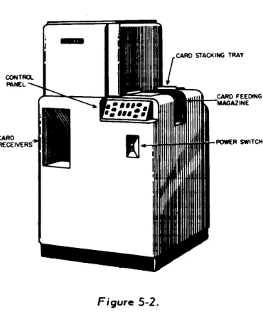
cards may be entered and the two receivers ("normal" and "sort") into which they are finally deposited.Figure 5-1. Figure 5-2.
Table 5-1
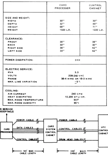
TE~JTATIVE INSTALLATION REQUIREMENTS
OF UNIVAC FI LE-COMPUTER 90-COLUMN CARD SYSTEM
CARD CONTROL
PROCESSER CABINET
SIZE AND WEIGHT:
WIDTH 30" 30"
DEPTH 32" 48"
HEIGHT 65" 71"
WEIGHT 1020 LB. 1220 LB.
CLEARANCE:
FRONT 35" 35"
BACK 30" 30"
RIGHT SIDE 36" 42"
LEFT SIDE 34" 42"
POWER DISSIPATION: 3KW
ELECTRIC SERVICE:
KVA 3.3
VOLTS 208-240 VAC
PHASE 30-4 W IRE OR 10-3 W IR E
MAX. LINE VARIATION
COOLING:
AIR CURRENT HEAT DISSIPATED
MAX. ROOM TEMPERATURE MAX. ROOM HUMIDITY
TO SERVICE RECEPTACLE
t
.... 5 ~,
-240 CFM
10,200 BT UI HR.
90F 90"'0
CARD
E~~~~~~~~~~~ SYSTEM CONTROL CABLES
AI
CONTROLCABINET
t.---:-
50'MAX.~
CABLE LENGTH
100' MAX.
--...oi~
. . CABLE LENGTHFigure 5-3. Cabling Diagram
UFC
SECTION
6
UNIVAC FILE-COMPUTER gO-COLUMN CARD SYSTEM
(with post-read checking)
The Univac File-Computer 90-Column Card System (with Post-Read Checking) may be used as a Univac File-Computer tabulating card input unit, as a card output unit, or as a
com-bined input-output unit. It is distinguished from the standard 90-Column Card System by added facil ities that allow the results of every \\read" or "punch" operation to be checked.
This \\post-read" checking consists of re-reading the processed card and checking it
against comparison data stored in the System.
T'-_ r .. _J. __ . . . ___ r"'l _ _ : _ _ J. __ " __ -' f'\f'\ 1"'_1.. _ _ J._'- .. I_J.: _ _ _ _ _ -' __ ..1_ 1_ J.L.. _ _ L.. _ _ _ _ _ _ ~
I l l e .Jy~lelli u~e~ f\t:::iIIiIIYlUIl f\dllU '1U-vUIUIIIII ldUUldllllY I..drU I..uut::. III lilt:: dU::>t::III..t:: UI
prolonged computations (exceeding 235 mill isec of computer time per card), it processes 150 cards per minute.
FUNCTIONAL DESCRIPTION
Used as an input device, the System reads information from cards and transmits it to the
computer. Used as an output device, the System accepts output information from the com-puter and punches it into cards. Used as a combined input-output device, the System per-forms both functions together. Except during manual run-in and ru'n-out operations, the System is controlled entirely by the computer commands received via the Computer-to-IO control lines. Conversely, the System may send program-altering signals to the computer
by way of the IO-to-Computer control lines.
However it is used, the System operates in a standard sequence that may be modified by control commands. Flexibi I ity of control is further extended by plugboard routing of data and control signals.
Standard Operation Sequence
The System is provided with a magazine that feeds cards through a card-processing channel
to a receiver. The channel picks the bottom card from the magazine, reads it, punches it, checks it, and deposits it in the receiver. Any of these processes may be without effect,
depending on the program. In an input operation, for example, the card passes through the punch process unchanged. The check process tests the results of previous read and punch processes by sensing the information on the card and comparing it with a block of
informa-tion stored in the System. (This "post-read" checking supplements parity checking.)
Repertoire of Control Commands
The System is able to execute any of the following four control commands: Trip, Skip, No Check, and Sort.
Trip. A Trip pulse initiates a card cycle. During each card cycle (except during run-in and run-out) one new (input) card is taken in and one processed (output) card is produced. At the end of each card cycle, the card processer automatically stops unless another Trip
pulse is received. A Trip pulse is produced whenever a Program Complete command is
received on one of the Computer-to-IO control lines.
Skip. A Skip pulse prevents the punch operation.
No Check. A No Check pulse inhibits the check operation.
Sort. A Sort pulse initiates the isolation of a selected card. £ach processed (output)
card is ordinarily deposited in what is called the "normal" receiver. If a Sort pulse is received, however, it is instead directed to another receiver, called the "sort" receiver.
This feature makes it possible to separate the cards into two categories on nearly any
basis. Typically, it is used to separate records that require action.
Plugboard Controls
The System includes a plugboar~ that permits format control, editing, check control, and other miscellaneous control operations.
card in any desired fashion and can insert unconditional signals wherever desired. Similar
plugboard controls apply to date entering the card punch. Thus the plugboard provides for format control and editing in every read or punch operation.
Check Control. The check process need not apply to all of the card. Plugboard patching determines what parts (if any) of the card are checked.
Miscellaneous Control Operations. The plugboard is provided with selector relays, "and"
(\\combine") gates, delay devices, busses, etc. so that many varied logical combinations
of control data may be ir11llemented by plugboard patching.
One of the Computer-ta-IO control I ines is reserved for Trip pulses. All other control lines between the computer and the System are connected to the System plugboard. The 10-to-Computer control I ines bear any control signals that can be read from cards; the 10-to- Computer-to-IO control lines may be patched directly to the SORT, SKIP, NO CHECK, and other exit hubs; or they may be connected to selectors etc. to provide more complex control functions.
PHYSICAL DESCRIPTION
The Univac File-Computer 90-Column Card System (with Post-Read Checking) consists of two separately housed sections: a type-4831 control cabinet and a type-4931 card processor.
Overall dimensions and other installation spec ifications for both sections appear in Table
6-1 and Figure 6-3.
Control Cabinet
The control cabinet (Figure 6-1> houses the connective circuitry (translators, registers,
etc.) between the card processor and the main computer. It includes a display panel
pro-vided with lights to indicate errors, contents of registers, etc. A concealed maintenance panel provides ready access to controls used in maintenance operations. The cabinet also
supports the plugboard and its receptacle.
Card Processor
The card processor (Figure 6-2) reads, punches, and sorts cards in accord with signals
from the control cabinet. It includes the feed magazine in which up to 600 cards may be
ACCESS ()()()R TO
l=\.uG9OARO
Figure 6-1. Type 4831 Control Cabinet
Figure 6-2. Type 4831 Carel Processor
TO SERVICE RECEPTACLE
r
V
CARD PROCESSER
POWER CABLE
JJ
DATA CABLES ~,
"
~CONTROL
CABLE ({II
POWER CABLE
"
)JCARD
SYSTEM CONTROL CABLES /I
CONTROL I)
CABINET
DRUM HEAD CABLES (I
IJ
-~
50'MAX~
CABLE LENGTH
100' M A X. - - - ! ...
I
CABLE LENGTH
Figure 6-3. Cabling Diagram
UFC CONTROL
Table 6-1
TENTATIVE INSTALLATION REQUIREMENTS
OF UNIVAC FILE-COMPUTER 90-COLUMN CARD SYSTEM (WITH POST~READ CHECKING)
CARD CONTROL
PROCESSER CABINET
SIZE AND WEIGHT:
WIDTH 40" 30"
DEPTH 30" 60-1/2"
HEIGHT 64" 71"
WEIGHT 1180 LB. 1560 LB.
CLEARANCE:
FRONT 24" 30"
BACK 24" 30"
RIGHT SIDE 24" 42"
LEFT SIDE 24" 42"
POWER DISSIPATION: 3KW
ELECTRIC SERVICE:
KVA 4.8
VOLTS 208-240 VAC
PHASE 30-4 W IRE OR 1£)-3 WIRE MAX. LINE VARIATION ±5%
COOLING:
AIR CURRENT 240 CFM
HEAT DISSIPATED 10.200 BTU/HR. MAX. ROOM TEMPERATURE 90F
SECTION
7
UNIVAC FILE-COMPUTER 80-COLUMN CARD SYSTEM (bull)
The Univac File-Computer SO-Column Card System (Bull) is used as a Univac
File-Com-puter tabulating card input unit, as a card output unit; or as a combined input-output unit.
It can operate simultaneously on two stacks of cards, punching output data into one stack
and reading input data from either or both stacks. Processing of the two stacks is
synchro-nized so that corresponding cards from each stack are processed simultaneously.
Except during manual run- in and run-out, the System is controlled entirely by computer
commands via the Computer-to-IO control I ines. Conversely, the System may send
proyram-altering signals to the computer by way of IO-to-Computer control lines.
The System uses standard SO-column card code and processes either or both stacks at 150
cards per minute in the absence of computational delays.
FUNCTIONAL DESCRIPTION
Operation of the System cons ists of a few bas ic processes performed in a standard sequence
that can be modified by control commands and plugboard patching. The many possible
types of operation are divided into two broad categories called Mode I and Mode II.
Bas ic Processes
The basic processes that the System can perform are reading, punching, checking, and
re-reading. The check process tests the results of previous read and punch processes by
sensing the information on the card and comparing it with a block of information stored in
the System. (This "post-read" checking is independent of parity checking, which is
per-formed elsewhere.> \\Re-reading" refers to an auxiliary reading process that is not used
Standard Operation Sequence
The System is provided with two card feeding magazines, each of which feeds cards through a separate channel to a corresponding receiver. The channels are called the "punch" and "read" channels, respectively.
The two channels work simultaneously, each performing three, parallel, sequenced oper-ations. The punch channel picks the bottom card from the punch magazine, reads it, punches it, checks it, and deposits it in the punch receiver. The read channel picks the bottom card from the read magazine, reads it, checks it, re-reads it, and deposits it in.
the read receiver. Operation of the two channels is synchronized so that the processing of corresponding cards from the two stacks may be co-ordinated.
Repertoire of Contrc;>1 Commands
The System performs any of the following seven commands that normally come from the computer via the Computer-to-IO control lines.
Program Complete. In passing from the magazine to the receiver of either channel, a card occupies a sequence of four intermediate stations. Each Program Complete command
initiates a card cycle---a mechanical process that advances the cards in both channels to the next station. At the end of each card cycle, the card processor automatically stops unless another Program Complete command is received. Five Program Complete commands are requir'ed to carry one card from each feed magazine to the corresponding receiver. The
Program Complete command is n'ormally sufficient to advance the cards from every station but two: the first station in each channel requires an additional "conditioning" signal to enable it to respond to a Program Complete signal.
Trip Read Feed. A Trip Read Feed command conditions the first station in the read
channel so that it can respond to the next (or simultaneous) Program Complete signal by
passing the card from the first station to the second.
Trip Punch Feed. A Trip Punch Feed command similarly conditions the first station in
the punch channel so that it can respond properly to a Program Complete.
Skip. A Skip command prevents the punch operation.
Punch Non-Check. A Punch Non-Check command similarly inhibits the check operation
in the punch channel.
Light Indicator. A Light Indicator command causes a particular lamp on the display
panel to light. This lamp indicates the presence of some programmer-selected condition
(such as "end of run") in the computer.
Plugboard Controls
The System includes a plugboard that permits format control, editing, check control, and
other miscellaneous logical operations.
Format Control and Editing. Whenever inforr.1ation is read from a card, it passes through
plugboard control. PI ugboard patching can therefore rearrange the array of data from the
card in any desired fashion and can insert unconditional signals wherever desired. Similar
plugboard controls apply to data entering the card punch. Thus the plugboard provides for
format control and editing in every read or punch operation.
Check Control. The check process need not apply to all of the card. Plugboard patching
determines what parts (if any) of the card are checked.
Miscellaneous Control Operations. . The plugboard is provided with selector relays,
delay devices, busses, etc. so that many varied combinations of control data may be
im-plemented by plugboard patching.
All control lines between the computer and the System are connected to the System
plug-board. The Computer-ta-IO control I ines entry hubs may be patched directly to the command
hubs (PROGRAM COMPLETE, TRIP READ FEED, etc.> and other exit hubs, or they may
be connected through selectors, etc. to provide more complex control functions.
The IO-ta-Computer control lines may bear any control signals that can be read from cards
in either channel. They may also carry four control signals that mark the beginning and
end of the file in each channel.
Mode I Operation
Mode I operation is any input-output operation in which all computer input data come from
the read channel and all output data are sent to the punch channel. The cards entered in
punch channel is not used (except perhaps, for control signals). Mode I operation allows
400 millisec of computer time per card and 150 cards per minute with (\\post-read")
check-ing in both channels.
Mode II Operation
Mode II operation is any input-output operation in which input data are read from cards in
the punch channel and the correspond ing output data are subsequently punched 011 the
same respective cards. The read channel !'lay be (1) unused, (2) used simultaneously to
enter unrel ated data in tile computer, or (3) used to provide computer input data augmenting
that read in the punch channel In the last case, the reading is synchronized so tllat data
from two corresponding cards---one in each channel---may enter the computer as two
dis-tinct input blocks or r.lay be merged to forr.l a single input block At 150 cards per minute
with "post-read" checking in both channels, the computer tirle per card is 80 rlillisec in
tile punch channel and 320 mi II isec in the read channel.
PHYSICAL DESCRIPTION
The Univac File-Computer 80-Column Card System (Bull) consists of two separately
housed sections: a type-4840 control cabinet and a type-4940 card processor. Overa II
dimensions and other install ation spec ifications appear in Table 7-1 and Figure 7- 3.
Control Cabinet
The control cabinet (Figure 7-1) houses the connective circuitry (translators, registers,
etc.) between the card processor and the main computer. It includes a display panel
pro-vided with lights to indicate errors, contents of registers, etc. A concealed maintenance
panel provides ready access to controls used in maintenance operations. The cabinet also
supports the plugboard and its receptacle.
Card Processor
The card processor (Figure 7-2) reads, punches, and checks cards in two channels in
accord with signals from the control section. It includes the two feed magazines, which
can hold stacks of up to 800 cards each; and two receivers, which are at the rear of the
,-4."'''''''''''t.'"'"" C.L"· ... t 4.
OtSPLAY (,. L " '"
MNEL ~ ... ~ 4..
~L'
OOOA TO
PLUGIIOARO
Figure 1-1. Type 4840 Control Cabinet
TO SERVICE RECEPTACLE
•
1
CARD PROCESSER
Figure 7-2. Type 4940 Cora Processor
I I
POWER CABLE ( POWER CABLE ((
/
»)
HCARD DATA CABLES
~t::: SYSTEM CONTROL CABLES (~
..
)::: CONTROLJT
-CABINET
~
CONTROL CABLE ~H DRUM HEAD CABLES (L}J
~ 50' MAX .----'~:MI CABLE LENGTH
loe~---100' MAX.---i~~
CABLE LENGTH
Figure 7-3. Cabling Diagram
i
Table 7-1
TENTATIVE INSTALLATION REQUIREMENTS OF UNIVAC FILE-COMPUTER aO-COLUMN CARD SYSTEM
SIZE AND WEIGHT:
WIDTH DEPTH HEIGHT WEIGHT CLEARANCE: FRONT BAC~
RIGHT SIDE LEFT SIDE
POWER DISSIPATION:
ELECTRIC SERVICE:
KVA
VOLTS
PHASE
MAX. LINE VARIATION
COOLING:
AIR CURRENT HEAT DISSIPATED
MAX. ROOM TEMPERATURE MAX. ROOM HUMIDITY
CARD PROCESSOR
30"
34" 49"
1000 LB.
30" 24" 24" 24" 3KW 4.S
208-240 V AC
CONTROL CABINET
30"
SO"
71"
1220 L 8.
42"
30"
33-1/2"
42"
3,0-4 W IR E OR 1.0-3 W IR E
+ 5 "10
1100 CFM
10,200 BT U/HR.
90F
SECTION
8
UNIVAC FILE-COMPUTER MAGNETIC TAPE UNIT
FUNCTIONAL DESCRIPTION
Capabil ities
The Univac File-Computer Magnetic Tape Unit (Figure 8-1) is a multi-purpose magnetic .
tape device which can be included in any Univac File-Computer installation.
Its fundamental purpose is to read, record and variously position mylar magnetic tape.
In the Univac Fi Ie-Computer System, three uses are made of this equipment:
1.
It is an InpuVOutput Unit for the Computer;2. It is in integral part of the Sort-Collate System; four of these Tape Units and a
Sort-Collate Unit form the Sort-Collate System;
3. It is the data source for off-I ine operation of the High-Speed Printer.
As an InpuVOutput Unit, the Univac File-Computer Magnetic Tape Unit is an on-line
de-vice and its operations are controlled by a computer program. However, except during
in-tervals in which control information is exchanged, the computer and Univac File-Computer
Magnetic Tape Unit operate independently.
As a part of the Sort-Collate System; the Univac File-Computer Magnetic Tape Unit is
entirely controlled by a Sort-Collate program during the actual file processing operations
of that system. Circuitry is provided however, so that in all collating operations of that
system, except the sort and sequence checking operations, the Sort-Collate program can
release control of the Univac File-Computer Magnetic Tape Units and allow the computer
to operate them as InpuVOutput equipments. The purpose of this feature, called Computer
Alert, is to permit collating and file-updating operations to be performed in a single pass
through the tape data. Upon completion of the updating routine the computer returns
con-trol of the Univac File-Computer Magnetic Tape Units to the Sort-Collate System. If the
Sort-Collate program is so plugged, the collating operation continues automatically
Use of the Univac File-Computer Magnetic Tape Unit as a data source for High-Speed
Printer operation is an off-line activity for both the Univac File-Computer Magnetic Tape
Unit and the High-Speed Printer.
Controls on the Univac File-Computer Magnetic Tape Unit permit manual operation of the
tape handler to position tape. These controls can be operated independently of the
com-puter, Sort-Collate System, or High-Speed Printer.
In this section, only the computer input-output functions of the Univac File-Computer
Magnetic Tape Unit are discussed. See Sections <) and
la,
respectively, for operation ofthis equipment in the Sort-Collate and High-Speed Printer Systems.
The Univac File-Computer Magnetic Tape Unit itself is designed for use only in a Univac
File-Computer System. However, 1 112 mil base mylar tapes prepared on this equipment in
compatible format and recording density can be used on other mylar tape-processing Univac
equipment, and vice-versa.
Medium
General. Mylar magnetic tape is the medium employp-rl in this device. The mylar base is
oxide coated and data is recorded by magnetizing minute spots on this coated surface.
Each spot is given one or the other of two polarities and accordingly is thought of as storing a \\1" or a
\\0",
Reading is accomplished by sensing these recorded spots.Data is recorded and read a I ine at a time. One standard 7-bit computer character is stored
on each line; and 120 consecutive lines (or characters form a blockette. Blockettes are
0.86" in length and are separated by 0.5" of
I"
blank spaces. The blockette is the tapeequipment's unit of format.
The principal programming unit is the File. Files are composed of a group of contiguous
items, each of which is a collection of consecutive characters that uniquely defines a
major fi Ie entry. A blockette may contain several Items; it may be an Item itself; or several
blockettes may be required for an Item. Items are phys ically recorded in blockette format,
but the number and sequence of characters they contain is determined by the recording
pro-gram on the basis of the File being recorded.
Associated with each blockette is a group of identifiers which are copies of the various
sets of data stored in the blockette. These identifiers can be used by the computer
Tape Specifications:
Width:
Base:
Recording Density:
Standard Length:
V2"
1
V2
mil mylar139 I ines/inch (Univac systems employing the standard
Univac 128 I ines/inch record ing density can read this
density; conversely, a recording density of 128 lines/inch
can be read by the Univac File-Computer Magnetic Tape Unit)
2500'
Number of Blockettes/Reel:
Blockette Spacing 2500' Length
0.5" 17,640
I"
12,600Mylar Tape Handler Spec1fications: (Potter Tape Unit, Model 3232)
Tape Transport Speed;
Read/Write Rate:
Start Time, Write:
Stop and Lockout Time:
Start Read Times:
75"/sec
10,400 characters/sec (single blockette type of operation)
(including acceleration and blockette spacing time)
0.5" blockette spacing: 7ms
I"
blockette spacing: 13 ms10 ms (This includes deceleration time and the lockout
or reverse direction time. The minimum time between
operations involving tape movement is thus 10 ms)
Operation
Read Forward after previous Read Forward
Read Forward after previous Read Backward
Read Backward after previous Read Forward
Read Backward after previous Read Backward
Blockette Read/Write Time:
Wind and Rewind Rates:
Bad Spot Detection:
Reel Changing:
0.5"
Blockette Spacing 1" Blockette Spac.7 ms 13 ms
2-3 ms 2-3 ms
2-3 ms 2-3 ms
7 ms 13 ms
11.5 ms (does not include start-stop time listed
above>
75"/sec; time required is approximately 9 1/2
minutes for 3600; length, and 6 1; 2 minutes for
2500' length. Checking performed during Rewind
operations.
Bad tape areas are photoelectrically sensed in
both forward and backward direction. Compatible
Bad Spot Logic.
By prethreaded, detachable tape leader.
110 Instructions. The Univac File-Computer Magnetic Tape Unit can execute the 13 1/0
instruct ions listed be I ow.
These 1/0 Instructions are sent to the Univac File-Computer Magnetic Tape Unit's Demand Station via the Computer-to-IO control lines when the Univac File-Computer Magnetic Tape
Unit is placed \\on demand",
Only one I/O Instruction can be given the Univac File-Computer Magnetic Tape Unit at a
WRITE
WRITE & CHECK
READ FORWARD
READ BACKWARD
SEARCH FORWARD EQUAL
SEARCH BACKWARD EQUAL
SEARCH FORWARD = or > SEARCH BACKWARD
=
or<
TRANSFER BUFFER
CONTENTS TO 110 TRACK
TRANSFER I/O TRACK
CONTENTS TO BUFFER
WIND FORWARD
REWIND
REWIND WITH INTERLOCK
Write, Write and Check, and Read operations are one-blockette operat