Volume 2010, Article ID 769683,18pages doi:10.1155/2010/769683
Research Article
“WBC over DVB-H” Testbed Design, Development and Results
Zhanlin Ji, Ivan Ganchev, and M´airt´ın O’Droma
Telecommunications Research Centre, University of Limerick, Limerick, Ireland Correspondence should be addressed to Ivan Ganchev,[email protected] Received 28 May 2009; Accepted 14 October 2009
Academic Editor: Faouzi Bader
Copyright © 2010 Zhanlin Ji et al. This is an open access article distributed under the Creative Commons Attribution License, which permits unrestricted use, distribution, and reproduction in any medium, provided the original work is properly cited.
The wireless billboard channels (WBCs) are integral part of the ubiquitous consumer wireless world (UCWW)—a wireless next generation network proposal. The WBCs are used by the service providers to broadcast advertisements of their (wireless) services to the mobile terminals so that the mobile users may discover and associate with the “best” services following the user-driven “always best connected and best served” paradigm. A three-layer system architecture of WBCs established over the digital video broadcasting-handheld (DVB-H) standard is presented. The design and development of a corresponding “WBC over DVB-H” experimental testbed are described. Various results obtained from the testbed are presented and explained.
1. Introduction
The wireless billboard channels (WBCs) [1–3] used for
service advertisement, discovery, and association (ADA) are fundamental to the consumer-centric business model (CBM), which is integral to the ubiquitous consumer
wireless world (UCWW) evolution [4,5]. The aim of CBM
is to enable mobile users (MUs) to be always best connected
and best served in UCWW [6], that is, to use the best service
anytime, anywhere, and anyhow through the best available wireless connection.
Taking into account the large number of services
avail-able to MUs in UCWW, an efficient and flexible mechanism
is needed for (i) service providers (xSPs) to advertise their services, (ii) consumers to discover favorite services and their updates, and (iii) mobile terminals (MTs) to associate with access networks and servers. The WBC is a novel solution for the above tasks.
In [1], WBCs are defined as narrow, unidirectional, and
point to multipoint broadcasting channels, operated by WBC service providers (WBC-SPs) and used to push wireless service advertisements simultaneously to a large number of MTs. To choose the “best” service, each MT filters out the received service descriptions (SDs) by using the user’s advertisement profile, discovery profile, association profile, history profile, terminal’s composite capabilities/preferences
profile (CC/PP) [7], and user location.
Broadcast technologies, both terrestrial and satellite, such as digital radio mondiale, digital audio broadcasting, digital video broadcasting-handheld (DVB-H), digital multimedia broadcasting, multimedia broadcast multicast service and are potential candidate carrier platforms for WBCs. Among these, the DVB-H standard deserves particular attention. This is a new digital standard for broadcasting video, audio, and multimedia datasets to portable and battery-limited MTs by employing the IP-datacasting (IPDC) technique. Several novel features are included in the DVB-H standard, such as a time-slicing, a 4 K modulation mode, a multiprotocol encapsulation-forward error correction (MPE-FEC), and a
depth interleaving [8,9]. This standard has the potential to
be exploited effectively in creating a WBC system. To check
the feasibility of “WBC over DVB-H”, it is first necessary to design a reasonable architecture and then to evaluate it by means of a suitable software/hardware testbed. To improve error protection in “WBC over DVB-H”, a new smart cross-layer decoding scheme for improving the reliability of WBC data casting was developed.
The design and development of a “WBC over DVB-H” testbed is the subject of this paper, which is organized
as follows. Section 2 presents the “WBC over DVB-H”
architecture.Section 3describes the WBC layers’ functional
model.Section 4focuses on the “WBC over DVB-H” testbed
design and implementation.Section 5presents some results
obtained from the testbed. FinallySection 6 concludes the
MT
OFDM 2 K 4 K 8 K DVB-H demodulator
TS
Extract data from MPE-FEC frame
Remove UDP and IP headers
WBC-ADP APIs Fixed-size segments object
(JSR 272)
WBC MT/MU middleware
SDs
MUs “WBC over DVB-H”
physical layer
“WBC over DVB-H” link layer
Service enabler sublayer
WBC service layer
Application enabler sublayer WBC-SP node
OFDM 2 K 4 K 8 K DVB-H modulator
TS
Construct MPE-FEC frame
Add UDP and IP headers
WBC-ADP server
Fixed-size segments object (JSR 272) WBCC & WBC multi-agents
middleware collecting, clustering scheduling, indexing Publish/submit SDs
xSPs
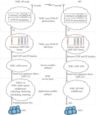
Figure1: The “WBC over DVB-H” layered architecture.
2. “WBC over DVB-H” Architecture
The “WBC over DVB-H” system is developed along three layers: a service layer, a link layer, and a physical layer.
Figure 1shows the “WBC over DVB-H” layered architecture. On the WBC-SP node, the wireless service advertise-ments are processed as follows. At the service layer, the SDs submitted by the corresponding xSPs are first collected, clustered, scheduled, and indexed by a WBC content server (WBCC), and the output is captured by a WBC
advertise-ments delivery protocol (ADP [2]) server for subsequent
UDP/IP packets generation. At the “WBC over DVB-H” link layer and physical layer, the IP packets are encapsulated into transport streams (TSs) and broadcasted on WBC by a DVB-H modulator. On MT, the SDs are processed in a reversed
order, as shown inFigure 1.
To achieve reliable broadcasting in unidirectional wire-less dispersive broadcasting channels, the forward error
correction (FEC) [10] schemes, used at the service layer, link
layer, and physical layer of “WBC over DVB-H” system, play an important role.
The functions of each layer are presented inSection 3.
3. WBC Layers’ Functional Model
3.1. WBC Service Layer. This layer is concerned with the
WBC service description model; service advertisement data collecting, clustering, scheduling, and indexing on WBC-SP node; and service discovery and association on MT (application enabler sublayer) and IPDC over ADP (service enabler sublayer).
3.1.1. WBC Service Description Model. An SD consists of a set
of attributes, such as service type, scope list, length, CC/PP, QoS, and attribute list. It is a basic element in WBC. Several formal languages can be used for abstract description of SDs, namely, the augmented Backus-Naur form (ABNF), the abstract syntax notation one-packed encoding rules
(ASN.1-PER) [11], the document type definition-extensible markup
language (DTD-XML), and so forth.Table 1 compares the
Table1: SD sizes in different formats.
SD Category ASN.1PER ABNF textual DTD-XML
encoding (bytes) encoding (bytes) encoding (bytes)
Bluetooth 61 189 93
SMS 91 274 449
News 123 343 601
Music CD 153 459 758
Voice call 188 583 921
UMTS/Wi-Fi 220 682 1078
WBCAService DEFINITIONS IMPLICIT TAGS :: =
BEGIN IMPORTS WBCAService FROM WBC;
AWBCAService :: = SEQUENCE {
service-Type Service-Type,
ccpp CCPP,
length SDLength OPTIONAL,
attributes Attributes }
Service-Type :: = SEQUENCE {
division OCTET STRING(SIZE(1..16)),
category OCTET STRING(SIZE(1..16)),
type OCTET STRING(SIZE(1..16)),
version OCTET STRING(SIZE(1..16)) }
CCPP:: = CHOICE {
defaultCCPP [0] SEQUENCE OF CCPPProperty,
notDefaultCCPP [1] SEQUENCE OF CCPPProperty }
Attributes :: = aWBCAService
END
Text-frame1
the SD encoding as the most efficient one among the formal
languages.
The ASN.1, published by the International Telecommu-nications Union-TelecommuTelecommu-nications sector, is well known as both a reliable description language that uses compactable encoding rules for specifying data in telecommunications protocols and is well tied to the Java programming language. An example of a SD template (WBCAService) in ASN.1
is shown in Text-frame 1 (Text-frame is a part of ASN.1
notation or XML code in this paper).
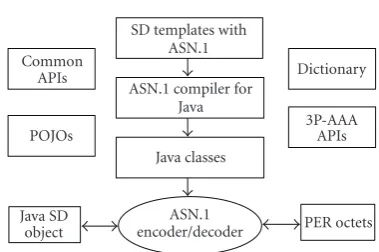
To integrate the ASN.1-PER scheme into the WBC service layer, all SD templates were compiled into Java classes
with an ASN.1 Java compiler (Figure 2).
The ASN.1-PER encoder/decoder depends on the Java classes used for encoding/decoding of a Java SD object into/from PER octets. The encoding of the SD example
(above) into a Java code is shown inAlgorithm 1.
3.1.2. WBC Application Enabler Sublayer. Considering that
the WBCs are narrow and MTs are limited in power, on WBC-SP node, all SDs need to be well organized to reduce the MT access time (the total amount of time from the moment when a mobile terminal first tunes in the WBC channel, until that the terminal receives the needed data.) and tuning time (the time that a mobile terminal keeps active
Dictionary 3P-AAA
APIs
PER octets SD templates with
ASN.1 ASN.1 compiler for
Java Java classes
ASN.1 encoder/decoder POJOs
Common APIs
Java SD object
Figure2: The ASN.1-PER encoding/decoding of SDs.
mode for listening to the WBC and receiving the needed data). On MT, discovery and association schemes working with user personal profile are used to enable the user to obtain and use easily information about the “best” wireless service(s).
To enable the ADA processing to run in an efficient way,
a goal-oriented, flexible multiagent system (MAS) [12] is
used for facilitating the proper coordination of all involved algorithms. Based on the foundation for intelligent physical
agents (FIPAs) framework [12], MAS job is to provide
Wbc.initialize ();
Coder coder = Wbc.getPERCoder (); ByteArrayOutputStream sink
= new ByteArrayOutputStream (); SampleWBCAService Sample = new SampleWBCAService (); coder.encode (Sample.valueWBCAService, sink);
byte [ ] encoding = sink. toByteArray ();
sink.close ();
Algorithm1
WBC knowledge
database Shared ontology
WBC rule engine Blackboard
Portal server Collecting
container
Clustering container
Scheduling container
Indexing container
WBC-SP manager
Message channel Agent execution environment
Gateway WBCC
Shared library
Enterprise application environment
· · · · · ·
· · · · · ·
· · ·
Figure3: The WBC-SP agent execution environment and enterprise application environment.
services, and message transport services. Each running instance of MAS is called a container with a set of agents.
(1) On WBC-SP Node. Considering the fact that in the next
ten years, the battery lifetime is expected to increase only
by 20%, the use of efficient power saving schemes is a key
element in WBCs. In [13] a broadcast disk algorithm was
introduced for reducing the access time, and in [14] an
(1,M) indexing scheme was proposed for reducing the tuning time. However, these and other existing algorithms cannot be applied directly in WBCs, because the unpopular SDs will be broadcast too many times. Our WBC solution includes four important agent-based schemes for SD collecting, clustering,
scheduling, and indexing. Figure 3 shows the WBC-SPs
agent execution environment at the application enabler sublayer.
The collecting agent is used to collect SDs from xSPs,
encode SDs into an ASN.1-PER stream, estimate SD broad-casting frequencies with collecting rules, generate plain old Java objects (POJOs) with shared ontology, and assert the facts (POJOs) into the working memory of the WBC rule engine, and so forth.
When the working memory is updated, the collecting
agent will send a message to the clustering agent for
regrouping SDs into fixed-size segments. The message is
rule sdarbitrary salience 10
when SD (f==$f && CCPP==$CCPP && QoS==$QoS
&& scopeList==$scopeList )
then input the SD to SD-sequence. end
Text-frame2
formatted with the agent communication language, and the content is described by ASN.1 to reduce the message size. Only same-category SDs are inserted into each WBC segment. In addition, SDs are ordered from the “hottest” to the “coldest” based on their broadcasting frequency. To generate reasonable SD sequence, a set of intelligent decision rules is applied, such as the CC/PP rule, QoS rule, ScopeList rule, and SD arbitrary rule. Using these rules, the clustering agent employs the “salience” conflict resolution strategy to
decide which rule should be “fired” [15]. An example of the
arbitrary rule as shown in Text-frame2.
Scheduling cache:
Segments: Hot A B C D E F G H I J K Cold
A B C A B A C B A
(a)
Scheduling cache Disk 3
(for cold segments of category 3)
Disk 1 (for cold segments
of category 1)
K G H
J I
G D A B C H A E B I A J C B A K F D
F E
Broadcast disk
Blackboard Scheduling agent
(rule decision maker)
(b)
Figure4: The scheduling model: (a) for hot segments; (b) for cold segments.
engine) and cold segment scheduling scheme (based on the broadcast disk algorithm and rule decision maker) are
used by the scheduling agent for generating the segments
broadcasting time and position. Let Fn denote the nth
segment broadcasting frequency, M the total number of
distinct segments in a broadcasting cycle, and N the total
number of segments in a broadcasting cycle.Figure 4shows
examples of the scheduling process for hot segments (A,B,C)
and cold segments (all others), whereFA=4,FB=3,FC=2,
Fothers = 1, M = 11, and N = 17. Segments A,D,E,F
are category 1, Bis category 2, andC,G,H,I,J, andK are
category 3.
With those reasonable and reconfigurable scheduling rules, the scheduling agent inserts all segments into the scheduling cache in a manner that reflects the user access pattern, meaning that the “hot” segments (of greatest user demand) are broadcast more frequently on WBCs in response to the users expectations.
When the scheduling cache is fully filled with segments,
theindexing agentstarts reading the scheduling information
from the blackboard and inserting an inner-index ASN.1-PER stream into each segment header and inter-index segments between regular data segments in the broadcasting cycle. This index information allows MTs to save battery power by staying in a sleep mode and only turning on when the SDs/segments that the user is interested in are broadcast on the billboard channel.
On the WBC-SP node, the WBCC server is the kernel of the agent execution environment for maintaining agents’ containers. In addition, a WBC portal server is provided with an enterprise application environment for maintaining the database, rule engine, SD template, xSP information, (price) competition algorithm, parameters of collecting, clustering, scheduling and indexing algorithms, querying, ontology, and so forth.
(2) On Mobile Terminal (MT). Users may set up their
own wireless personal area network (WPAN) environment, including a cell phone, personal digital assistant, ultramobile PC, and laptop. MTs in this WPAN may connect to each other with Bluetooth, Zigbee, Z-wave, and so forth. To achieve personalized service discovery and association, the
user may define different personalized roles for different
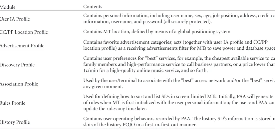
MTs. For example, the user may use a limited-capabilities cell phone for voice call service and an ultramobile PC with acceptable display resolution for high data rate e-Learning services. A personal assistant agent (PAA) runs on each MT for intelligent management of MT identification, device CC/PP and location, personal user profiles, history, recommendation, rules, and so forth. PAA communicates with the middleware of MT’s WBC application (iWBC) for user identification/authentication (IA) processing.
In the CC/PP standard [7], the terminal software,
hardware, and browser are defined by a resource description framework (RDF) with XML. Considering that the reading and writing RDF files need extra application programming interfaces (APIs) for supporting input/output operation, to make the WBC system simple, the CC/PP information is described with a string-vector and stored into the user profile.
The iWBC personal user profile includes a number of
modules as shown inTable 2.
Table2: The iWBC User Profile’s General Description.
Module Contents
User IA Profile Contains personal information, including user name, sex, age, job position, address, credit cardinformation, username, and password (all securely protected).
CC/PP Location Profile Contains MT location, defined by means of a global positioning system.
Advertisement Profile Contains favorite advertisement categories; acts (together with user IA profile and CC/PPlocation profile) as a receiving advertisements filter for MTs to save power and database space.
Discovery Profile
Contains user preferences for “best” services, for example, the cheapest available service to call family members and high-performance service to call business partners, or a price lower than 1c/min for a high-quality online music service, and so forth.
Association Profile Used by the user/terminal to associate with the “best” access network and/or the “best” service atany given moment.
Rules Profile
Used for defining how to sort and list SDs in screen-limited MTs. Initially, PAA will generate a set of rules when MT is first initialized with the user personal information; the user and PAA can update the rules any time later.
History Profile Contains user operating behaviors recorded by PAA. The history SD’s information is stored in theslots of the history POJO in a first-in-first-out manner.
In iWBC MAS, beside PAA, an advertisement moni-toring agent listens on WBCs to receive new (or updated) SDs/segments based on the advertisement profile, user IA profile, CC/PP, and location profile, a searching agent communicates with PAA to send requests and receive responses to/from the discovery profile and rules profile, and a recommendation agent works with the history profile for updating the user profile with an intelligent learning
algorithm (Figure 5).
3.1.3. WBC Service Enabler Sublayer. “All-IP” is one of the
visionary goals for next generation networks, where MTs will receive all wireless service advertisements from xSPs over an IP-based backbone. To smooth the IPDC processing, a new reliable and scalable ADP protocol was elaborated to convert WBC segments into IP packets.
Several reliable and unidirectional packet-level FEC schemes have been developed recently, for example, file
delivery over unidirectional transport (FLUTE) [16], file
multicasting (FCAST) [17], and so forth. However in
addi-tion to being complex, these schemes use extra XML/meta-data and produce large overhead; thus they are not suitable for the narrowband WBCs. ADP was developed based on the
modified asynchronous layered coding (ALC) protocol [16].
The ADP’s FEC scheme uses Reed-Solomon (RS) algorithm to guarantee packet-level reliable IPDC.
Full comparison between the ADP, FLUTE, and FCAST
protocols is presented inTable 3.
(1) ADP Protocol Instantiation. The reliable multicast
trans-port working group has published a set of standards for one-to-many multicasting, in terms of building blocks (BBs) and
protocol instantiation (PI) [18]. BBs are basic components
which can plug/unplug into/from PI. Four BBs have been specified: layered coding transport (LCT), FEC, congestion control, and authentication. Two types of PIs have been
designed: ALC (using FEC) and negative acknowledgement oriented reliable multicast relying on FEC with automatic repeat request. As WBCs are simplex channels, congestion control BB and authentication BB are pointless to use and thus not adopted by ADP. In addition, the standard LCT BB and FEC BB needed redesigning in ADP to improve the WBC
system performance and efficiency of MT encoders/decoders.
The objects being broadcast by ADP are fixed-size WBC segments. In our ADP solution, each segment is defined as one source block and identified by a unique segment
sequence number. Figure 6 shows the process of segment
transformation into ADP encoding symbols—source (data) symbols and FEC symbols. Each ADP packet only contains
one encoding symbol. An efficient FEC scheme is applied on
the encoding symbols generation. For instance, hot segments and index segments use higher FEC code rate than cold segments and nonindex segments.
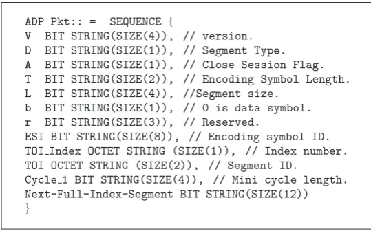
(1) ADP Packet Format. The ADP adds its own header to
each encoding symbol. The ADP header is formatted with
ASN.1 as shown in Text-frame3.
The total size of the ADP header is only 8 bytes. Comparing with the Flute header (44 bytes) and FCAST
header (60 bytes), the ADP is more efficient in terms of both
the overhead and complexity.
(2) ADP Decoding Schemes. Two decoding schemes are used
by ADP: (i) a packet erasure decoding (PED) scheme for low-end MTs, and (ii) a packet erasure plus byte error decoding (PE + BED) scheme for high-end MTs.
(3) PED Scheme. An ADP packet is considered either
received or lost. Everynencoding symbols includeksource
(data) symbols and (n-k) parity (repair) symbols. MT can
decode a WBC segment if any k symbols (out of n) are
SDs monitor
agent Recommendation
agent User
profiles Mobile
user
Switch on MT & login iWBC
Welcome information
Update profiles Update
Shadow of userprofile New
New New Read profile
Decode & update Decode &
update
Update history
Update profile Uprpofiledate
Update profiles in working memory Put profile facts into working memory ACK & load profiles
Monitor WBC (if ‘best’ advertisement is sent, receive the segment)
ACK
Result
Result Search action with MU profile Search with
keyword Search action
Switch off
MU authentication and authorization PA
agent
Searching
agent
Working
memory
Result ACL message
Serialize Serialize
Inform MAS to DAO
Stop monitoring WBC Learningprogress with user activities
Inform Read
Figure5: The time sequence diagram of the interaction between agents, profiles, and working memory.
Table3: ADP, FLUTE, and FCAST Comparison.
Features ADP FLUTE FCAST
Standard No Yes Yes
FEC Supported Only RS Any Any
Cross-Layer Decoding Yes No No
Congestion Control Not needed in WBC Support Support
Push or Pull Push only Both Both
File Properties ASN.1 XML FDT Meta-Data
Redundancy Control Yes (QoS) No No
Large File Support Not needed in WBC Yes Yes
File Segmentation Not needed in WBC Yes Yes
Header Size 8 bytes 44 bytes 60 bytes
PE +BED Scheme. If a WBC segment fails to decode, the
corresponding ADP header in the segmen’s reserved area (r) will be modified and marked as “1.” This helps the receiver
decode the segment as shown inAlgorithm 2.
3.2. “WBC over DVB-H” Link Layer. The WBC service layer
is a software layer with a common structure for all WBC nodes and is independent of the carrier technology. On the
contrary, the WBC link layer and physical layer are hardware
dependent layers and thus may have different structures
depending on the carrier technology used.
The WBC link layer acts as an interface between the service layer and the physical layer for converting the IP packets into TS packets and vice versa. A “WBC over DVB-H” link layer protocol data unit (PDU) encapsulation
Source symbols
ADP
FEC symbols
ADP packet UDP/IP packet database
Broadcasting agent
Header 1001101
UDP ADP protocol
IP/IPSec Broadcast
API
101010101010 010101010101 010101010101
101010 101010 010101
010101
010101
010101
1001101 1001101 Segment/source
block
ADP encoding symbols
Figure6: The ADP packets generation and UDP/IP encapsulation.
ADP Pkt:: = SEQUENCE {
V BIT STRING(SIZE(4)), // version.
D BIT STRING(SIZE(1)), // Segment Type.
A BIT STRING(SIZE(1)), // Close Session Flag.
T BIT STRING(SIZE(2)), // Encoding Symbol Length.
L BIT STRING(SIZE(4)), //Segment size.
b BIT STRING(SIZE(1)), // 0 is data symbol.
r BIT STRING(SIZE(3)), // Reserved.
ESI BIT STRING(SIZE(8)), // Encoding symbol ID. TOI Index OCTET STRING (SIZE(1)), // Index number. TOI OCTET STRING (SIZE(2)), // Segment ID.
Cycle 1 BIT STRING(SIZE(4)), // Mini cycle length. Next-Full-Index-Segment BIT STRING(SIZE(12))
}
Text-frame3
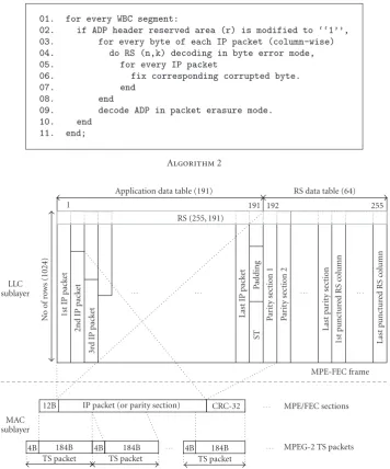
3.2.1. MPE-FEC. The MPE-FEC frame is the core PDU
at the link layer. MPE-FEC was introduced into DVB-H for compensating the performance degradations due to wireless fading channels. The MPE-FEC frame consists of 255 columns and a number of rows (256, 512, 768, or 1024
[9]). Every cell in the MPE-FEC frame contains one byte.
One MPE-FEC frame carries a number of 4–8 kB WBC segments. The 255 columns are divided into two sections: from 1st to 191st column is the MPE section (application data table—ADT), and from 192nd to 255th column is the FEC section (RS data table).
3.2.2. Encapsulating and Encoding Algorithms. The IPv6
packets are encapsulated into the ADT column-wise one by one. A smart 8-byte segment table (ST) is inserted at
the end of ADT to help decoder running in an efficient
way. This table includes the size of the erasure information table (EIT), the number of WBC segments in one MPE-FEC frame, and other parameters of ADP. The RS (255, 191) encoder generates 64 RS parity bytes for each ADT row. After constructing the entire MPE-FEC frame, it is sent down to the media access control (MAC) sublayer, where each IP packet in ADT and each column in the RS data table are extracted from the MPE-FEC frame and then encapsulated into a separate MPE/FEC section. Finally the MPE/FEC sections are plotted into MPEG-2 TS packets and sent down to the physical layer for broadcasting on WBC.
3.2.3. Decapsulating and Decoding Algorithms. Even thought
the encapsulating and encoding schemes are determined in the DVB-H standard, they are opened for end-users’ design
and implementation. In [9], a section erasure (SE) decoding
scheme is suggested at the MAC sublayer. The MPE packet is first decapsulated from the received TS packets and a CRC-32 error-detection algorithm verifies it. If no errors are detected, the MPE/FEC section is marked as “reliable;” otherwise it is marked as “unreliable.” Then the IP packet is decapsulated from the MPE/FEC section. The IP packet together with the CRC verification result is sent to the logic link control (LLC) sublayer, where the IP packet is inserted in the relevant column(s) of the MPE-FEC frame. The corresponding column of EIT is filled with “0” or “1,” that is, “0s” for “reliable” packets and “1s” for “unreliable” ones. When the MPE-FEC frame is full, the decoding algorithm checks the number of “1s” in the MPE section and the number of “0s” in the FEC section of EIT. For any row, if the number of “1s” is smaller than the number of “0s,” then the MPE-FEC frame can be decoded with the RS(255,191) code; otherwise the MPE-FEC frame should be discarded.
01. for every WBC segment:
02. if ADP header reserved area (r) is modified to ‘‘1’’,
03. for every byte of each IP packet (column-wise)
04. do RS (n,k) decoding in byte error mode,
05. for every IP packet
06. fix corresponding corrupted byte.
07. end
08. end
09. decode ADP in packet erasure mode.
10. end
RS data table (64) Application data table (191)
1 191 192 255
RS (255, 191)
MAC sublayer
12B IP packet (or parity section) CRC-32 MPE/FEC sections MPE-FEC frame
MPEG-2 TS packets
4B 184B 4B 184B 4B 184B
TS packet TS packet TS packet
Figure7: The “WBC over DVB-H” link layer PDU encapsulation.
3.3. “WBC over DVB-H” Physical Layer. This layer is based
on the DVB-T standard and three new features as guided in [9]:
(i) transmission parameter signaling—used to enhance
and speed up the service discovery;
(ii)4 K mode—offers an additional trade-off between
the single-frequency network cell size and mobile reception performance;
(iii)in-depth symbol interleaving—increases the
flexibil-ity of the symbol interleaving thus improving the robustness in mobile environments and impulse noise conditions.
From the viewpoint of the top layer (link layer), the “WBC over DVB-H” physical layer is envisaged as a binary symmetric noisy fading channel.
4. “WBC over DVB-H” Testbed Design
and Implementation
4.1. WBC Service Layer
4.1.1. Application Enabler Sublayer. An object-oriented (OO)
software development methodology was chosen in this sublayer to develop a three-tier architecture as shown in
Figure 8.
Service Discovery and Maintenance Tier. This tier provides a
HTML/WML/Applet MIDP/CDC/Aandroid
GWT AJAX WEB
service WEB application
context IoC container
WBC web/ MU MVC
Presentation sub-tier Remote/local service builder
Portlet API (JSR-168) WBC AOP
APIs Local/remote
POJO APIs Business
delegates Business
logic APIs
Business sub-tier DAO
Mail O/R mapping
Persistence sub-tier Service discovery and maintenance tier
DB WBC
algorithms
Application tier Gateway agent
Other agents
MAS container tier WBC agents
Personal assistant agent
Shared blackboard Yellow page
services Main WBC
container
IPDC APIs Rule
engine APIs Shared
ontology APIs Common
APIs
M
essage
ch
annel
Figure8: The WBC application enabler sublayer’s architecture.
Table4: The Main APIs at the WBC Service Layer.
API Descriptions
JADE
The Java agent development environment (JADE) is an efficient MAS released by the Telecom Italia lab with FIPA specifications standard. It is a free open-source software under the terms of the lesser general public license (LGPL). Website:http://jade.cselt.it/.
Prot´eg´e A free ontology editor and knowledge base framework generating common objects, which act asontology for communication at WBC service layer. Website:http://protege.stanford.edu/.
Drools/Jess
Act as rule-engine-based expert systems in WBC. Drools is developed by JBOSS with LGPL; website:http://www.jboss.org/drools/. Jess (academic licensed) is developed by Sandia National Laboratories; website:http://www.jessrules.com/.
Jena An open-source semantic web framework API for reading and writing CC/PP RDF files. Website:http://jena.sourceforge.net/.
OSS The Nokalva OSS ASN.1 tool for Java API generates PER octets stream from the ASN.1 BNF file(academic-licensed). Website:http://www.oss.com/.
GWT A Google web toolkit; asynchronous JavaScript XML (AJAX) applications designing tool,developed by Google with LGPL. Website:http://code.google.com/webtoolkit.
Android SDK
An opening handset alliance project. Application is designed with Java and runs on Dalvik; middleware runs on Linux system. Developed by Google with LGPL. Website:
http://code.google.com/android.
WBC Server A lightweight HTTP(s) server handling HTTP events, such as request handler, and responsedispatcher, developed by TRC, University of Limerick, Ireland.
Taking into account that the Java EE/Java SE/Java ME are effi -cient and hardware independent platforms for building both enterprise applications and portable-devices applications, the Java platform was selected for the implementation of the WBC service layer in order to provide system uniformity,
distribution, and portability.Table 4lists the main Java
open-source and academic-licensed IDEs/APIs/Frameworks which were used at the WBC service layer.
The service discovery and maintenance tier consists of three subtiers.
(i)Presentation subtier. On WBC-SP node, this can
operate in local mode (HTML/WML/Applet) or
remote (web service) mode to receive responses
and send requests from/to the WBCs portal server (the xSP personal profiles and history datasets are stored on the portal database). On MT, to find the favorite SDs, the user runs a mobile infor-mation device profile/connected device configura-tion/Android application to match the received SDs to his/her profile (the bulk of this work is done by PAA). Beside the portable application, the user can run a small GWT AJAX application to manage his/her WPAN environment in local/remote mode. A
set of design patterns is used at this subtier: a
model-view-controller module that isolates business rules
from user interface objects and aninversion of
con-trol pattern (dependency injection) that minimizes
dependencies of the other subtiers and uses a factory class for the creation and assembling of objects with configuration files (maintained by an application context component). In addition, the later improves the system testability and loose-coupling property (i.e., a “mock” object can be injected into the WBC test environment for replacing a “live” service; in that each business module only depends on configuration files).
(ii)Business subtier. Facades and delegates are the key
design patterns at this sub-tier. By hiding complex business APIs and exposing a simpler interface
[19], business services are decoupled from clients
and agents. Moreover, the maintenance cost can be reduced because business rules can be redefined by modifying the business delegates XML files. There are four types of business delegates located at this sub-tier: a graphical user interface (GUI), a WBC agent, a Java message service/Database, and a WBC data processing business delegates. For example, the GUI business delegate can cache data and user requests, ask for a Java message service feedback, interact with the persistence sub-tier and other two tiers for man-aging the persistence data and other WBC services, send results to the clients’ forms or web services, and so forth. With this concept of business delegates, the overall WBC system development and testing
are much more cost efficient. At this sub-tier, beside
business delegates, the business logic APIs provide interfaces for the persistence sub-tier and application tier; the WBC aspect-oriented programming (AOP)
APIs work with the IoC container to facilitate modularization of crosscutting concerns (i.e., to
enable encapsulation of functionality that affects
multiple classes in separate units); the local/remote POJO APIs are used for generating JavaScript object notation objects; a portlet API aggregates several content sources for xSPs with a single web archive file.
The remote/local service builder acts a bridge between the presentation tier and business sub-tier.
(iii)Persistence subtier. There are three main components
located at this sub-tier: a mail component concerned with sending mail notifications to xSPs, WBC-SP, and MUs; an O/R mapping component used for conver-sion between Java objects and a relational database; and a data access object (DAO) component used to
abstract and encapsulate all accesses with different
data source, such as relational databases, XML, and OO databases. All SD PER streams are carried by Java POJOs and serialized into an OO database. The xSP roles and other relevant information are serialized to relational databases.
(2) Intelligent Application Tier. To achieve a loose-coupling
system and enable WBC ADA processing to run in an intelligent way, a rule-based expert system operates at this tier for facilitating the data broadcasting in the WBC-SP node and data receiving in MTs. An ontology technique is used to describe concepts and their relationships. The design pattern of ontology follows the singleton design pattern to enable sharing the same object among the three tiers. Each ontology scheme is built up with vocabulary, concept, predicate, and action. The other APIs at this tier (common APIs, WBC-SDs processing APIs, IPDC APIs, etc.) are shared with the other two tiers.
(3) MAS Container Tier. This is an agent run-time
environ-ment tier for facilitating the collection, clustering, schedul-ing, indexschedul-ing, and broadcasting of SDs in WBC-SP node and their discovery and association in MTs. The JADE was selected to develop a MAS with two types of agents: logic-based agents (e.g., the collecting, clustering, scheduling, indexing, broadcasting, monitoring, searching, and recom-mendation agents), and belief-desire-intention agents (e.g., PAA), whose actions depend on the user history records, plans, beliefs/desires, and intentions. A shared blackboard and a gateway agent are used for communication between agents and tiers. A message channel is shared by this tier and the service discovery and maintenance tier as shown in
Figure 8.
4.1.2. Service Enabler Sublayer. The ADP protocol running at
this sublayer is implemented with C++ on Linux platform. A Java native interface—ADP middleware was developed which acts as a bridge between the Java environment and
Init Ready
New Seg
Send Pkts
Send start Finish End
State NIL
Recv start Finish End
State NIL Close K Pkt Recv
Recv Reset
Figure9: The ADP send/receive finite state machine.
way, a multithread scheme working under a Finite State Machine was designed for optimizing the business logic of
the send/receive process (Figure 9).
4.2. “WBC over DVB-H” Link Layer
4.2.1. Hardware Implementation. A UDcast real-time
DVB-H encapsulator (IPE-10) and DVB-DVB-H analyzer
(GOLDE-NEAGLE) [20] were selected for the hardware
implementa-tion of the link layer.
IPE-10 includes all standard DVB-H link layer’s func-tionalities and in addition provides a novel solution for IP encapsulation management, bandwidth allocation, QoS enforcement, statistical channels multiplexing, and so forth.
The equipment specification is 19 1U in size and 16.7 kg
in weight. The network interfaces include Ethernet, asyn-chronous serial interface (ASI) output, and others. The dataset being broadcast in “WBC over DVB-H” can use a dedicated narrow DVB-H channel or a shared TV channel (IP packets are broadcast in spare bandwidth).
GOLDENEAGLE is a DVB-H reception equipment which provides real-time MPE-FEC frame analyzing and monitoring the nonnominal behavior of the DVB-H sys-tem to help WBC service providers find potential prob-lems. The input signal of GOLDENEAGLE includes ASI
interface and antenna. The equipment is 19 half 2U in
size and 10 kg in weight. The supported communication protocols include HTTP, TCP/IP, SNMP, FTP, and Telnet. Moreover, it supports MPEG-2, MPE, and IP level analy-sis.
The parameters of IPE-10 and GOLDENEAGLE can be set via a designed WBC portal application. However, GOLDENEAGLE only supports the standard SE decoding algorithm. Hence, to compare this to our own SSE decoding algorithm, this layer is implemented in software for perfor-mance simulation experiments.
4.2.2. Software Implementation. The “WBC over DVB-H”
link layer software testbed was designed and implemented
with C++. The encoder’s functional model is depicted in
Figure 10. The decoder (running on the MT) uses a reversed functional model.
4.3. “WBC over DVB-H” Physical Layer (PHY)
4.3.1. Hardware Implementation. An Audemat DVB-H
transmitters (EMAA) [21] and Teamcast DVB-H portable
demodulator (POD-1100) [22] were selected for the physical
layer’s hardware implementation.
EMAA is a fully DVB-T/DVB-H compliant modulator. It supports ASI and USB TS stream input and radio frequency (RF) and intermediate frequency signals output.
The equipment is 19 half 2U in size and 10.1 kg in
weight. The modulation settings can be saved as profiles in EMAA, which then can be modified via the WBC portal application.
POD-1100 is a potable USB DVB-H demodulator. It integrates a new generation DIBCOM DVB-H chipset and supports 5 MHz, 6 MHz, 7 MHz, and 8 MHz RF channels. The output port of POD-1100 is USB 2.0, and the physical
size is 15∗4∗2 CM, 0.25 Kg. The WPAN lightweight
MU-iWBC server can be tuned on this equipment to define the PID and FEC parameters via the MU-iWBC client appli-cation. However, to achieve greater freedom and flexibility in playing with PHY parameters for system evaluation (i.e., estimating the TS packet error rate (TSPER) in Rayleigh fading channels), we implement this layer in software as
described inSection 4.3.2.
4.3.2. Software Implementation. The TSPER in real dispersive
wireless environments is an important criteria to define the “WBC over DVB-H” system parameters, such as optimal IP packet length, WBC segment size, and SDs data organization schemes. Considering that a DVB-H wireless channel sim-ulator is not currently available on the market, a software physical layer testbed was built based on the
ETSI-EN-300-744 standard [23] by using Matlab on Linux platform, as
shown inFigure 11(the data processing on MT (receiver) is
performed in a reversed order).
The physical fading channel design follows the COST 207
model in typical urban reception conditions [24], which has
been commonly used for wireless broadcasting simulations.
The channel simulation parameters are shown in Table 5
(delay is the path delays vector inμs, relative power is the
average path gains vector in dB).
5. Results
5.1. Software Implementation. Developing the whole “WBC
over DVB-H” system follows the personal software process
methodology [25]. An experience repository database was
IP packets
Build MPE-FEC frame, generate ST table, insert it at the end of IP section of MPE-FEC frame
Install IP packets into MPE-FEC frame. Add RS parity data
Finish Finish
LLC sublayer
Extract each RS column from FEC section, insert MPE header and CRC-32 trailer, put resultant
MPE packet into cache Extract first/next IP packet from
IP section of MPE-FEC frame, insert MPE header and CRC-32 trailer, put resultant MPE packet
into cache
No No Done for all RS columns? Done for all IP
packets?
Yes Yes Build TS packets and put theminto TS buffer table (when
becoming full, signal this event to the physical layer)
No
Yes End Done for all waiting
WBC segments ?
MAC sublayer
Figure10: The “WBC over DVB-H” link layer encoder’s functional model.
functional models (features), such as login model, SDs encoding/decoding model, SDs organization model, history-log viewer model, and DVB-H broadcasting and receiv-ing model. For each unit model, from bottom tier to top tier, unified modeling language diagrams following the corresponding interface were first designed. Then the interface was fully implemented and a unit testing was performed.
5.1.1. WBC-SP Node. Figure 12(a) shows the hardware
equipment rack of the WBC-SP node as follows (top-down): UDcast IPE-10, WBC-ADP server (IBM ThinkPad),
SHUNRA Internet simulator [26], UDcast GOLDENEAGLE,
Audemat ETAA modulator, and WBC content server (DELL 1U PowerEdge server).
Figures 12(b) and 12(c) show the WBC portal pages
including four tabs: (i) the MAS tabmaintains the
WBC-JADE environment, (ii) the portal tab is used for
start-ing/stopping the Java EE distributed environment and
recording log-information of the entire system, (iii) the
WBC APP tab is the entrance to the WBC-portal (it
mainly includes WBC SD collecting, clustering, scheduling, indexing, and broadcasting sections; in addition the link layer’s and physical layer’s parameters can be defined by the corresponding Portlet in a remote mode), and (iv)
the send tab is a remote control panel to control the
ADP server to broadcast WBC segments/SDs in a carousel way.
5.1.2. Mobile Terminal (MT). Figure 12(d)shows the MU’s
WPAN hardware equipment as follows (top-down): iWBC center, Android Google phone, and POD-1100 receiver.
Figure 12(e) shows the iWBC WPAN server-side
appli-cation. It includes two tabs: (i) the receiver tab controls
remotely POD-1100 to receive the broadcasting dataset
via the wireless channel; (ii) the iWBC-APP tab is a
TS packets
RS (204, 188) encoder Outer convolutional
interleaver
GF2 bit convector
Inner convolutional coder Division into OFDM
symbols
Inner interleaving
OFDM modulation
FFTsize=4∗1024; Carrier num=3409; Useful num=3024; Con pilot=89; TPS num=34; Bandwidth=8; Guardsize=1/4;
Freq=700; Vehicle=60;
Doppler=Freq∗Vehicle/1080; Power vec=−[3 0 2 6 8 10]; Delay vec=. . .;
ray chi=raychi (. . .);
No
Yes Decoding processing
BER & TS statistic Done for all 68
frames ?
Fading AWGN channel
Figure11: The “WBC over DVB-H” physical layer testbed.
Table5: Channel parameters.
Path Number Delay (μs) Relative power (dB) Doppler Spectrum
1 0.0 −3 Rayleigh
2 0.2 0 Rayleigh
3 0.5 −2 Rayleigh
4 1.6 −6 Rayleigh
5 2.3 −8 Rayleigh
6 5.0 −10 Rayleigh
module. Figure 12(f) shows the iWBC Android
appli-cation. An Android-JADE gateway facilitates communi-cation between the Android Google phone and iWBC WPAN.
5.2. Performance Simulation Results. The system
perfor-mance was evaluated by mean of pure software “WBC over DVB-H” testbed for reasons explained above. The simulation
runs in offline mode, that is, on WBC-SP node, the service
layer’s/link layer’s output is saved in a binary file, which then serves as an input to the link layer/physical layer. On MT side, the physical layer’s/link layer’s output is saved in a binary file as an input to the link layer/service layer. The physical layer’s TSPER, link layer’s IP packet error rate (IPER) and segment error rate (SER), and service layer’s mean segment tuning time and access time are the main criteria for performance evaluation of the “WBC over DVB-H” system.
5.2.1. “WBC over DVB-H” Physical Layer. The TSPER
simulation results in Figure 13(a)—obtained by using the
parameters listed in Table 5—show that the TSPER
per-formance degrades with increasing the Doppler frequency
(fD) from 10 Hz, through 40 Hz, and to 80 Hz,
respec-tively.
5.2.2. “WBC over DVB-H” Link Layer. The IPER and
SER simulation results are shown in Figures 13(b) and
13(c), respectively. Observations based on these results as follows.
The Doppler Effect. As can be seen from the results, the
IPER/SER becomes worse when the Doppler frequency increases. Thus, in order to achieve IPER/SER less than
1% (WBC datacasting requirement) when fD = 80 Hz,
the received SNR should be about 1.2–2.5 dB higher than that
(a) Sch. DCO SessionPIDPackets
sent Bytes sent Bytes
dropped Queuelength RowsData/FE
TELECOMMUNICATION RESEARCH CENTRE, UNIVERSITY OF LIMERICK
Main Menu
Administration SDs List Start Jade Clustering
Scheduling
Indexing
Broadcasting
Link Layer Conf Physical Layer conf Logout
WBC-JADE Remote Agent Managemen… WBCC
‘‘10.100.149.34:1099/JADE’’ Main-Container
Container-1
[email protected]:1099/JADE [email protected]:1099/JADE [email protected]:1099/JADE [email protected]:1099/JADE [email protected]:1099/JADE [email protected]:1099/JADE [email protected]:1099/JADE
[email protected]:1099/JADE Container-2 Container-3
[email protected]:1099/JADE Optimization: Bandwidth:
Sending File finalsequence/segment 6 ∗∗∗Stripping file finalsequence / segment6 into 1 fragment(s) Sending file finalsequence/segment6 slice 1 (Data: 8000 Bytes-Trailer: 140 Bytes) File finalsequence/segment6 (8000 Bytes) sent.
1 fragments (objects) transfered for this file.
8148 Bytes transfered for this file. Sending File finalsequence/segment 7 ∗∗∗Stripping file finalsequence/segment 7 into 1 fragme Sending file finalsequence/segment 7 slice 1 (Data: 8000 File finalsequence/segment 7 (8000 Bytes) sent. 1 fragments (objects) transfered for this file.
8148 Bytes transfered for this file. Sending File finalsequence/segment 8
∗∗∗Stripping file finalsequence/segment 8 into 1 fragme Sending file finalsequence/segment 8 slice 1 (Data: 8000 File finalsequence/segment 8 (8000 Bytes) sent. 1 fragments (objects) transfered for this file.
8148 Bytes transfered for this file. Sending File finalsequence/segment 9 ∗∗∗Stripping file finalsequence/segment 9 into 1 fragme Sending file finalsequence/segment 9 slice 1 (Data: 8000 File finalsequence/segment 9 (8000 Bytes) sent. 1 fragments (objects) transfered for this file.
8148 Bytes transfered for this file. Log:
Profile: DEF… ADP size:
Statistic: Repeat mode: send 10 times
222
225.100.100.100
WBC APP
TELECOMMUNICATION RESEARCH CENTRE, UNIVERSITY OF LIMERICK
Multicast Group (or unicast IP)
TELECOMMUNICATION RESEARCH CENTRE, UNIVERSITY OF LIMERICK
receive
WBC-JADE Remote Agent Management WBCC
‘10.50.3.23:1099/JADE’ Main-Container
[email protected]:1099/JADE [email protected]:1099/JADE [email protected]:1099/JADE [email protected]:1099/JADE [email protected]:1099/JADE [email protected]:1099/JADE [email protected]:1099/JADE [email protected]:1099/JADE [email protected]:1099/JADE [email protected]:1099/JADE [email protected]:1099/JADE [email protected]:1099/JADE IICS M-Commerce Services:AD-44357766
IICS Entertainment Services
IICS Message Services
IICS Education Services
iWBC Android iWBC Android
MENU MENU
Welcome to ADExplorer iWBC Option
(f)
Figure12: The “WBC over DVB-H” system and GUI. (a) WBC-SP’s rack; (b) WBC portal for traffic monitoring; (c) WBC portal for
10 12 14 16 SNR (dB)
0.001 0.01 0.01 1
TS
PE
R
fD=80 Hz fD=40 Hz fD=10 Hz
(a)
10 12 14 16
SNR (dB) 0.001
0.01 0.1 1
IP
ER
SE,fD=80 Hz SE,fD=40 Hz SE,fD=10 Hz SSE in LLC,fD=80 Hz SSE in LLC,fD=40 Hz SSE in LLC,fD=10 Hz
PE + BED in SL,fD=80 Hz PE + BED in SL,fD=40 Hz PE + BED in SL,fD=10 Hz
(b)
10 12 14 16
SNR (dB) 0.001
0.01 0.1 1
SER
SE,fD=80 Hz SE,fD=40 Hz SE,fD=10 Hz SSE in LLC,fD=80 Hz SSE in LLC,fD=40 Hz SSE in LLC,fD=10 Hz
PE + BED in SL,fD=80 Hz PE + BED in SL,fD=40 Hz PE + BED in SL,fD=10 Hz
(c)
500 1000 1500 2000
Number of distinct segments in a broadcasting cycle (M) 0
500 1000 1500 2000 2500
M
ean
seg
m
ent
ac
ce
ss
time
(time
slots)
“WBC over DVB-H”, SNR=16 dB,fD=40 Hz “WBC over DVB-H”, SNR=13 dB,fD=40 Hz Virtual channel
Broadcast disks algorithm WBC algorithm Ideal (no collision)
(d)
The Cross-Layer Smart Decoding Effect. The cross-layer smart MPE-FEC decoding algorithm works with SSE and ADP (packet erasure mode) to improve reliability at the link layer. The results show that, for IPER/SER less than 1%, the gain advantage is about 0.6–1 dB if using the SSE scheme instead
of SE for fD=10 Hz and about 1-2 dB for fD=80 Hz.
5.2.3. “WBC over DVB-H” Service Layer
The ADP PE + BED effect. At the service layer with the
ADP packet erasure plus byte error decoding scheme, for IPER/SER less than 1%, the gain advantage is about 0.5–1 dB comparing to SSE at the LLC sublayer.
The Indexing Effect. With the developed “WBC over
DVB-H” indexing scheme, the tuning time is reduced to τ =
Probe wait + Innerindex reading time + Interindex reading
time + Segment downloading time≈0.5 + 1 + 1 + 1=3.5
timeslots.
The Access Time. To measure the access time, the
broadcast-ing ofM =500 distinct segments was simulated. The client
access pattern was assumed to follow the Zipf distribution
with an access skew coefficientθ=0.6.
The simulation results in Figure 13(d) show that the
mean segment access time increases when the number of distinct segments in the broadcasting cycle increases too. These results prove that WBC data organization algorithm
is more efficient than the broadcast disks algorithm [13].
The access time for SNR = 13 dB is greater than that
for SNR = 16 dB due to higher SER. The access time
in “WBC over DVB-H” is greater than that in a virtual channel due to extra FEC data added to the broadcasting segment sequence to improve the error detection and cor-rection.
6. Conclusion
A three-layer system architecture of wireless billboard channels (WBCs) established over digital video broadcast-handheld (DVB-H) carrier for service advertisement, dis-covery, and association (ADA) in a ubiquitous consumer wireless world (UCWW) has been presented in this paper. The design and development of corresponding experimental testbed have been described in detail.
At the WBC service layer, the service providers (xSPs) submit/publish service descriptions (SDs) of their services to the WBC service provider (WBC-SP)’s portal in a very active, dynamic, intelligent, and competitive manner. The services are then encoded, collected, clustered, scheduled, indexed, and sent to an advertisement delivery protocol (ADP) server for IP data casting (IPDC). On the other side, the mobile terminals (MTs) use the index infor-mation embedded in the WBC dataset to filter out the uninterested/unwanted SDs. After discovering the needed services, the terminals associate with the “best” service(s) in each preferred category. The service layer has been implemented with Java and C++ in a Linux environment.
An intelligent WBC-SP’s distributed portal application and a mobile user (MU)’s WPAN environment have been fully implemented.
At the “WBC over DVB-H” link layer, a novel cross-layer smart section erasure (SSE) decoding scheme has been proposed to improve the reliability of IPDC over wireless fading channels. The link layer’s software testbed simulation results show that the cross-layer smart section
erasure decoding is more efficient than the standard section
erasure decoding.
At the “WBC over DVB-H” physical layer, an ETSI 300–744 compatible broadcasting solution has been imple-mented. The corresponding part of the software testbed
working in offline mode has been designed with Matlab.
Various simulation results obtained from the developed testbed have been presented and explained.
Acronyms
Acronym Definition
ABNF: Augmented Backus-Naur form
ADA: Advertisement, discovery and association
ADP: Advertisements delivery protocol
ADT: Application data table
ALC: Asynchronous layered coding
APIs: Application programming interfaces
ASI: Asynchronous serial interface
ASN.1: Abstract syntax notation one
BB: Building block
CBM: Consumer-centric business model
CC/PP: Composite capabilities/preferences profile
DTD-XML: Definition-extensible markup language
DVB-H: Digital video broadcasting-handheld standard
EIT: Erasure information table
FCAST: File multicasting
FEC: Forward error correction
FLUTE: File delivery over unidirectional transport
FIPA: Foundation for intelligent physical agents
GUI: Graphical user interface
JADE: Java agent development framework
IA: Identification/authentication
IPDC: IP Datacasting
IPER: IP packet error rate
iWBC: Formerly your WBC personalized receiver
LCT: Layered coding transport
LLC: Logic link control
LGPL: Lesser general public license
MPE-FEC: Multi-protocol encapsulation-forward error correction
MAC: Media access control
MAS: Multi-agent system
MT: Mobile terminal
MU: Mobile user
PAA: Personal assistant agent
PDU: Protocol data unit
PE + BED: Packet erasure plus byte error decoding
PED: Packet erasure decoding
PER: Packet encoding rule
POJO: Plain old Java object
RDF: Resource description framework
SD: Service description
SE: Section erasure
SER: Segment error rate
RS: Reed-Solomon
SSE: Smart section erasure
ST: Segment table
TS: Transport stream
TSPER: TS packet error rate
UCWW: Ubiquitous consumer wireless world
WBC: Wireless billboard channel
WBCC: WBC content server
WBC-SP: WBC service provider
WPAN: Wireless personal area network
xSP: Service provider.
Acknowledgment
This publication has been supported by the Irish Research Council for Science, Engineering and Technology (IRCSET), and the Telecommunications Research Centre, University of Limerick, Ireland.
References
[1] P. Flynn, I. Ganchev, and M. O’Droma, “Wireless billboard channels: vehicle and infrastructural support for advertise-ment, discovery, and association of UCWW services,” in Annual Review of Communications, vol. 59, pp. 493–504, International Engineering Consortium, Chicago, Ill, USA, 2006.
[2] Z. Ji, I. Ganchev, and M. O’Droma, “Performance Evaluation of ‘WBC over DVB-H’ System,” IEEE Transactions on Con-sumer Electronics, vol. 55, no. 2, pp. 754–762, 2009.
[3] Z. Ji, I. Ganchev, and M. O’Droma, “Building a ‘WBC over DVB-H’ software testbed,” in Proceedings Book of the 13th International Symposium on Consumer Electronics (ISCE ’09), pp. 769–772, Kyoto, Japan, May 2009.
[4] M. O’Droma and I. Ganchev, “Toward a ubiquitous consumer wireless world,”IEEE Wireless Communications, vol. 14, no. 1, pp. 52–63, 2007.
[5] M. O’Droma and I. Ganchev, “Strategic innovations through NGN standardisation for a ubiquitous consumer wireless world,” in Proceedings Book of the 1st ITU-T Kaleidoscope Academic Conference, Innovations in NGN, K-INGN, pp. 135– 142, Geneva, Switzerland, May 2008.
[6] M. S. O’Droma and I. Ganchev, “Enabling an always best-connected defined 4G wireless world,” in Annual Review of Communications, vol. 57, pp. 1157–1170, International Engineering Consortium, Chicago, Ill, USA, 2004.
[7] G. Klyne, F. Reynolds, C. Woodrow, H. Ohto, J. Hjelm, and M. H. Butler, “Composite Capability/Preference Profiles (CC/PP): Structure and Vocabularies,” W3C Recommenda-tion, 2004.
[8] M. Kornfeld and G. May, “DVB-H and IP datacast—broadcast to handheld devices,”IEEE Transactions on Broadcasting, vol. 53, no. 1, pp. 161–170, 2007.
[9] ETSI, “Digital video broadcasting (DVB); DVB-H implemen-tation guidelines,” Tech. Rep. TR 102 377, V1.2.1, ETSI, Cedex, France, 2005.
[10] M. Luby and L. Vicisano, “Compact Forward Error Correction (FEC) Schemes,” RFC 3695, February 2004.
[11] H. Qiang, Z. Xue-Cheng, and S. Shi-Min, “ASN.1 application in parsing ISUP PDUs,” inProceedings Book of the International Symposium on Communications and Information Technologies (ISCIT ’06), pp. 78–81, Bangkok, Thailand, September 2006. [12] F. Bellifemine, A. Poggi, and G. Rimassa, “JADE a FIPA2000
compliant agent development environment,” in Proceedings Book of the 5th International Conference on Autonomous Agents, pp. 216–217, Montreal, Canada, May-June 2001.
[13] S. Acharya, R. Alonso, M. Franklin, and S. Zdonik, “Broadcast disks: data management for asymmetric communication environments,” in Proceedings Book of the ACM SIGMOD International Conference on Management of Data, pp. 199–210, San Jose, Calif, USA, May 1995.
[14] T. Imielinski, S. Viswanathan, and B. R. Badrinath, “Data on air: organization and access,”IEEE Transactions on Knowledge and Data Engineering, vol. 9, no. 3, pp. 353–372, 1997. [15] L. Padgham and M. Winikoff, Developing Intelligent Agent
Systems: A Practical Guide, John Wiley & Sons, New York, NY, USA, 2004.
[16] T. Paila, M. Luby, R. Lehtonen, V. Roca, and R. Walsh, “FLUTE -file delivery over unidirectional transport,” RFC 3926, October 2004.
[17] V. Roca, “FCAST: scalable object delivery on top of the ALC protocol,” IETF RMT Working Group, draft-roca-rmt-newfcast-00.txt, February 2007.
[18] T. Whetten, L. Vicisano, R. Kermode, M. Handley, S. Floyd, and M. Luby, “Reliable multicast transport building blocks for one-to-many bulk-data transfer,” RFC 3048, January 2001. [19] J. Greenfield and K. Short, Software Factories: Assembling
Applications with Patterns, Frameworks, Models and Tools, John Wiley & Sons, New York, NY, USA, 2004.
[20] UDCast,http://www.udcast.com/. [21] Audemat,http://www.audemat.com/. [22] Teamcast,http://www.teamcast.com/.
[23] ETSI, EN 300 744, “Digital Video Broadcasting (DVB); framing structure, channel coding and modulation for digital terrestrial television,” V1.5.1, November, 2004.
[24] COST 207 Report, Digital Land Mobile Radio Communi-cations, Commission of European Communities, Directorate General, Telecommunications, Information Industries and Innovation, Luxemburg, Denmark, 1989.
[25] W. S. Humphrey,PSP: A Self-Improvement Process for Software Engineers, SEI Series in Software Engineering, Addison-Wesley, Reading, Mass, USA, 2005.


![Real time processing on the road: a guided tour of [iks]'s abstr/cncr setup](data:image/gif;base64,R0lGODlhAQABAIAAAP///wAAACH5BAEAAAAALAAAAAABAAEAAAICRAEAOw==)