Effect of Vertical Stiffness Irregularity on
Multi-Storey Shear Wall-framed Structures
using Response Spectrum Analysis
Hema Mukundan
1, S.Manivel
2P.G. Student, Department of Civil Engineering, SRM University, Kattankulathur, Tamilnadu, India1
Assistant Professor (O.G), Department of Civil Engineering, SRM University, Kattankulathur, Tamilnadu, India2
ABSTRACT: Urbanization has led to housing problems. This has resulted in the rise of several Multi-storey and High-rise buildings. Hence Structural Dynamics study has been steadily increasing over the years. The modern trend is towards tall and slender structures (Irregular) and innovative architecturally designed structures like the Baha‟i temple (Lotus shaped). These buildings are affected by environmental factors like wind, earthquake and waterways. Millions of people world-wide annually die due to earthquakes which are responsible for billions of rupees of property damage. This has necessitated the study of Earthquake Engineering. However, study and research in the field of Irregular Buildings under seismic conditions is gaining momentum. The provision of shear wall in building has been found effective and economical. In this paper, a 10 storey building in Zone IV is presented to reduce the effect of earthquake using reinforced concrete shear wall-framed structures in the building. The results were tabulated by performing Response spectrum analysis using ETABS version 9.7.4 in the form of maximum storey displacements, base shear reactions, mode shapes and storey drifts. Effect of Irregularity was studied by creating openings in shear wall and by varying the thickness of Shear wall, along the storey‟s.
KEYWORDS:Base Shear, Multi-storey Buildings, Response Spectrum Analysis, Seismic loading, Shear wall-framed structures, Vertical stiffness.
I.
I
NTRODUCTION1.1 General Aspects
Stability of earth is always disturbed due to internal forces which causes vibrations or jerks in the earth's crust known as an earthquake. Earthquakes which are unpredictable and a devastating natural disaster produces low - high waves which vibrate the base of the structure in various manners and directions, so that lateral force is developed on the structure. Oscillation / Vibration (motion which repeats itself after an interval of time) in structural systems results due to wind, earthquake, height etc. Dynamics is concerned with the study of forces and motions which are time dependent. When a structure is subjected to dynamic load, it starts vibrating resulting in the displacement of the structure. Seismic zones IV & V are high intensity earthquake zones. After the recent Bhuj earthquakes, tsunami in Indonesia, there is a growing interest in the process of designing civil engineering structures capable of withstanding dynamic (earthquake-induced) loads. Shear walls are Concrete/masonry vertical walls serving both architecturally as partitions and structurally to carry gravity & lateral loading. Their very high in-plane stiffness and strength makes them ideally suited for bracing tall buildings. They are usually continuous down to the base to which they are rigidly attached to form vertical cantilevers. In this paper, study was done on a regular Multi-storey building (G+9) with / without shear wall understanding parameters like storey drifts, lateral loads, mode shape patterns, time period, base shear, and storey
deflections. Three types of vertical irregularities were modelled.Effect of Irregularity was studied by creating openings
in shear wall & by varying the thickness of the Shear wall, along the storey‟s.
1.2
Regular & Irregular Configuration (As per 1S 1893 (Part 1):2002
A. Plan Irregularities - a) Torsion Irregularity, b) Re-entrant Corners, (c) Diaphragm Discontinuity, (d) Non- parallel Systems
B. Vertical Irregularities – a) Stiffness Irregularity, b) Mass Irregularity, (c) Vertical Geometric Irregularity, (d) Discontinuity in Capacity – Weak Storey
Buildings are designed as per Design based earthquake (DBE), but the actual forces acting on the structure is far more than that of DBE. So, in higher seismic zones Ductility based design approach is preferred as it narrows the gap. The primary objective in designing an earthquake resistant structure is to ensure ductility to withstand the earthquake forces.
1.3 Objective
To evaluate lateral load behaviour of Multi-Storey Ductile Shear wall and Special Moment Resisting Frame structure (Dual Systems) with Vertical Stiffness Irregularities by studying the following parameters:-
Top Storey Deflection, Drift Pattern, Mode Shape Pattern, Base Shear & Time period.
1.4 Scope
a) To Analyse Shear wall Frame structures with time periods.
b) Wall frame structure forms part of Institutional buildings
c) Analysis corresponding to Zone IV.
d) The analysis was done using Response Spectrum Method
1.5 Need for Research
Irregular buildings constitute a large portion of the modern urban infrastructure. Structures are never perfectly regular and hence the designers routinely need to evaluate the likely degree of irregularity and the effect of this irregularity on a structure during an earthquake. Need for research is required to get economical & efficient lateral stiffness system for high seismic prone areas. For optimization & design of high rise building with different structural framing systems subjected to seismic loads. To improve the understanding of the seismic behaviour of building structures with vertical irregularities.
II.
LITERATURE SURVEY2.1 Related Work
Literature review teaches us that an irregular structure needs a more careful structural analysis to resist Earthquake damages.
Venkata Sairam Kumar. N & et al (February 2014) carried out research mainly on application of cyclic load tests and behaviour of different types of shear walls in cyclic application of loads. Shear walls can be used as lateral load resisting Systems and also retrofitting of structures. Internal shear walls are more efficient than External shear walls when compared with cyclic load tests by researchers.
Ravikanth Chittiprolu, Ramacharla Pradeep Kumar, (June 2014) performed study on dynamic linear analysis using response spectrum method and lateral load analysis was done for structure with shear wall and structure without shear wall. Results were compared for the frame lateral forces and storey drifts of both the cases. It was inferred that shear walls are more resistant to lateral loads in an irregular structure. Storey drift is reduced in case of structure with shear wall. Also they can be used to reduce the effect of torsion.
Varsha R. Harne (2014) carried out a study to determine the strength of RC Shear wall of a multi-storied building by changing shear wall location. 3 different cases of shear wall position for a 6 storey building have been analyzed. Incorporation of shear wall has become inevitable in multi-storey building to resist lateral forces. Among all the load combination, the load combination of 1.5 DL + 1.5 EQX is found to be more critical combination for all the models. It was found that shear walls are more effective when located along exterior perimeter of the building. Such a layout increases resistance of the building to twisting.
distribution of lateral forces evolved through seismic action in each storey level due to changes in stiffness of frame on vertically irregular frame. As per the Bureau of Indian Standard (BIS) 1893:2002 (part 1) provisions, a G+10 vertically irregular building was modelled as a simplified lump mass model for the analysis with stiffness irregularity at Fourth floor. To response parameters like story drift, story deflection and story shear of structure under seismic force under the linear static & dynamic analysis was studied. This analysis showed focus on the base shear carrying capacity of a structure and performance level of structure under severe zone of India. The result remarks the conclusion that, a building structure with stiffness irregularity provides instability and attracts huge storey shear. A proportionate amount of stiffness is advantageous to control over the storey and base shear. The soft computing tool and commercial software which was used was CSI-ETABS (version 9.7) for modelling and Analysis.
S.Kumbhare, A.C. Saoji (2012) had carried out study on the effect of seismic Loading on placement of shear wall in medium rise building at different alternative location. They found that frame type structural system becomes economical as compared to dual type structural system and can be used for medium rise residential building situated in high seismic zone.
Ashish S. Agrawal, S.D.Charkha (2012) carried out study on 25storey building in Zone V by changing various position of shear wall with different shapes for determining parameters like storey drift, axial load and displacement. From the results of analysis they came to a conclusion that placing shear walls away from centre of gravity resulted in increase in most of the member forces. Also they found that displacement of the building floor at storey 25 has been reduced due to the presence of shear wall place at the centre.
Y.M. Fahjan & J. Kubin & M.T. Tan (2010) found that in the countries with active seismicity, reinforced concrete structural walls are widely used in multi-storey structure systems. Therefore, a proper modelling of the shear walls is very important for both linear and nonlinear analyses of building structures. The shell element can be used efficiently for the analysis of building structures with shear walls. The shell element considered in most of the design software has 6 degrees of freedom at each node and an in-plane rotational degree of freedom, which makes it compatible with three-dimensional beam-type finite element models. Shear wall modelling requires mesh discretization in order to get realistic behaviour. The advantage of using shell elements is the ability to model very long, interacting and complex shear walls within the three dimensional model.
G. Nandini Devi, K.Subramanian & A.R.Santhakumar (June 2009) studied a three bay R.C frame without and with shear wall in middle bay which was subjected to static cyclic lateral load. Shear wall of one bay was subjected to static reversed cyclic lateral load to assess its individual behaviour. Cyclic effects on the shear wall frame were considered for comparison. Shear wall frame and dual frame was compared to assess the individual behaviour of shear wall and when it is designed with beam column Frame. It was found that in spite of carrying large load, the dual frame exhibited less top storey deflection. At the initial stage of loading the dual frame was 7.84 times stiffer than the bare frame and 4.84 times higher than the shear wall frame. At service load (50% of the ultimate load, the dual frame is 10.56 times stiffer than the bare frame and 6.76 times stiffer than the shear wall frame. When the frames are compared at service load, it was found that the dual frame can be used for a larger service load and can withstand higher seismic loads with small deflection.
J.Kubin, Y.M.Fahjan and M.T.Tan (2008) studied the different approaches of modelling the shear walls in structural analyses of buildings and compared their results. The shear walls within the building structures are generally modelled by either a composition of frame elements or a mesh of shell elements. In modelling shear walls with “shell elements” the drilling moment of the shear walls and the bending moment of the in-plane connected beams are changed dramatically with mesh density. For finer meshes, 10% reduction of the drilling moment can be estimated. Introduction of top Chord frame stabilize the results considerably. Good estimation of the properties of the top chord frame is very important to not affect the overall stiffness of the structural system. Best results are obtained using a top chord frame element to enhance the fixity of the beams framing into the shear wall.
Devesh P. Soni and Bharat B. Mistry (2006) studied the seismic response of vertically irregular building frames and found that the largest seismic demand is found for the combined–stiffness–and–strength irregularity. The methodology proposed by Fragiadakis et al (2006) proposed a methodology based on Incremental Dynamic Analysis (IDA) to evaluate the response of structures with „single-story vertical irregularities‟ in stiffness and strength using a nine-story steel frame. The methodology proposed by him enables a full range performance evaluation via a highly accurate analysis method that pinpoints the effects of any source of irregularity. He concluded that vertical irregularities produce different effects which depend on the type of irregularity, the storey where it happens and most importantly, on the intensity of earthquake or equivalently on the response level or damaged state of the structure.
III.SELECTIONOFTHESTRUCTURE
3.1 General
a) Material used was M25 Grade Concrete.
Analysis Property Data
b) Yield stress fy = 415 N/mm2
c) Compressive Cube Strength of Concrete = 25 N/mm2
d) Poisson‟s ratio = 0.2
e) Analysis was done using ETABS Software 9.7
3.2 Building Details
a) Type of frame: Special RC moment resisting frame fixed at the base
b) Seismic zone: IV
c) Number of storey: G+9
d) Floor height: 3.0 m
e) Depth of Slab: 120 mm
f) Size of beam: (250 × 450) mm
g) Size of column: (300 × 450) mm
h) Spacing between frames : (i) 6 m in X & Y direction (General), (ii) 24 m × 15 m in X & Y direction
i) Live load on floor: 2 kN/m2
j) Floor finish: 1.5 kN/m2
k) Wall load: 14 kN/m
l) Materials: M 25 concrete, Fe 500 steel Material
m) Thickness of wall: 230 mm
n) Thickness of shear wall: 150 mm
o) Density of concrete: 25 kN/m3
p) Density of masonry wall : 19 kN/m3
q) Type of soil: Medium
r) Response spectra: As per IS 1893(Part-1):2002
s) Damping of structure: 5 percent
IV.PLANNINGANDMODELLING
4.1 Seismic Analysis
Earlier, the buildings were designed just for gravity loads but in recent times, Seismic analysis is a major tool in earthquake engineering used to understand the response of buildings due to seismic excitations in a simpler manner .
Different types of earthquake analysis methods are: Equivalent Static Analysis, Response Spectrum Analysis, Time
History Analysis
4.2 Response Spectrum Analysis
This approach permits the multiple modes of response of a building to be taken into account. For each mode, a response is obtained from the design spectrum, corresponding to the modal frequency and the modal mass, and then they are combined to estimate the total response of the structure. Following are the types of combination methods:
(a) absolute - peak values are added together , (b) Square root of the sum of the squares (SRSS), (c) Complete quadratic combination (CQC) - a method that is an improvement on SRSS for closely spaced modes.
4.3 Model Showing Different Types of Irregularities
Fig. 4.1 showing Plan Irregularity – L shaped Fig. 4.2 showing Stiffness Irregularity
Plan Irregularity is shown in Fig. 4.1 & in Fig. 4.2, height of the storey is varying. It is called as soft storey. Buildings on Stilts will fall under this category.
Fig. 4.3 showing Vertical Geometric Irregularities
Vertical Geometric Irregularity is shown in Fig. 4.3. A vertical setback is a geometric irregularity in a vertical plane. The setback can be visualized as a vertical re-entrant corner.
4.4 Comparison of Models for Regular configuration with/without Shear Walls
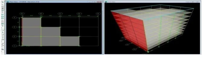
Plan View 3-D View Fig. 4.4 showing G + 9 Storey Building with Shear wall
Plan View 3-D View Fig. 4.5 showing G + 9 Storey Building without Shear Wall
Shear walls are quick in construction, because concreting of the members is done using formwork. Since Shear walls give such a high level of precision, it doesn‟t require any extra plastering or finishing.
4.5 Comparison of Models for Irregular configuration with openings in Shear wall / without openings
in Shear Walls
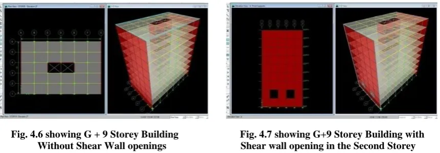
Fig. 4.6 showing G + 9 Storey Building Fig. 4.7 showing G+9 Storey Building with Without Shear Wall openings Shear wall opening in the Second Storey
Building with G+9 Storey‟s showing Shear wall without any opening/with opening in 2nd
storey are shown in Fig. 4.6 & 4.7
As per IS: 1893 (Part 1 2002, Table 8 Percentage of Imposed Load to be Considered in Seismic Weight Calculation
(cl. 7.3.1) Imposed load considered for the G+9 Storey Building was taken as 3 kN/m2
4.6 Load Combinations
The following five load combinations were used for G+9 storey with shear wall & without shear wall. DL + IL 1.5 (DL + IL) 1.2 (DL + IL ± EL) 1.5 (DL ± EL) .0.9 DL ± 1.5 EL
4.7 Calculation of Seismic Base Shear as per IS 1893 (Part 1): 2002
The Response spectra is a plot of maximum response versus T (for fixed ξ) for a given ground motion. This is response in terms of force, displacement, acceleration, shear force etc.
The total design lateral force or design seismic base shear (Vb) along any principal direction is:
Distribution of Shear in Multi-Storied Building
The design Base Shear (Vb) computed is distributed along the height of the building as per the expression:
(4.1) Qi = Vb × [ Wi h i ÷ Ʃ Wi hi 2
]
Design Horizontal Seismic Coefficient can be calculated as :
(4.2) Ah = Z/2 × I/R × Sa / g
As per IS 1893 (Part I) - 2002, the natural period of vibration (Ta), in seconds, Ta = 0.075 h0.75 for RC frame building
Ta= 0.085 h0.75for steel frame building, where h is the height of the building .
Fig. 4.8 Maximum storey Fig. 4.9 Maximum storey Displacements Displacements – with Shear wall – without Shear wall
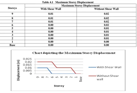
Table 4.1 Maximum Storey Displacement
Storeys With Shear Wall Maximum Storey Displacement Without Shear Wall
9 0.01 0.02
8 0.01 0.02
7 0.01 0.02
6 0.00 0.02
5 0.00 0.01
4 0.00 0.01
3 0.00 0.01
2 0.00 0.01
1 0.00 0.00
Base 0.00 0.00
Fig. 4.10 Chart showing Maximum Storey Displacement
Fig. 4.8 & 4.9 show ETAB output. Table 4.1 is the value got by analysis & Fig. 4.10 represents the data in graphical
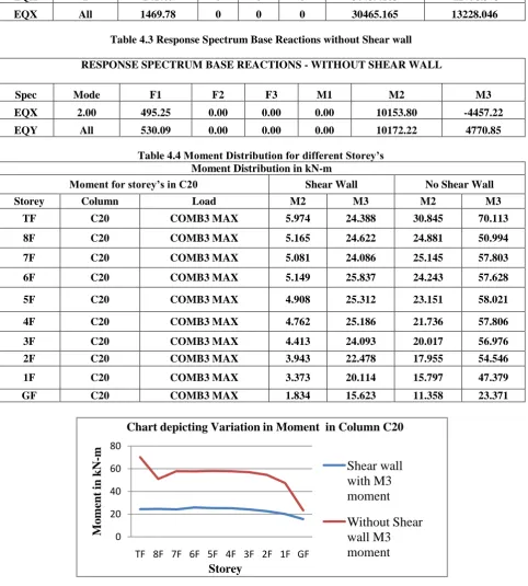
Table 4.2 Response Spectrum Base Reactions with Shear wall RESPONSE SPECTRUM BASE REACTIONS - WITH SHEAR WALL
Spec Mode F1 F2 F3 M1 M2 M3 EQX 2 1417.6 0 0 0 30439.163 -12758.373 EQX All 1469.78 0 0 0 30465.165 13228.046
Table 4.3 Response Spectrum Base Reactions without Shear wall RESPONSE SPECTRUM BASE REACTIONS - WITHOUT SHEAR WALL
Spec Mode F1 F2 F3 M1 M2 M3 EQX 2.00 495.25 0.00 0.00 0.00 10153.80 -4457.22 EQY All 530.09 0.00 0.00 0.00 10172.22 4770.85
Table 4.4 Moment Distribution for different Storey’s Moment Distribution in kN-m
Moment for storey’s in C20 Shear Wall No Shear Wall Storey Column Load M2 M3 M2 M3
TF C20 COMB3 MAX 5.974 24.388 30.845 70.113 8F C20 COMB3 MAX 5.165 24.622 24.881 50.994 7F C20 COMB3 MAX 5.081 24.086 25.145 57.803 6F C20 COMB3 MAX 5.149 25.837 24.243 57.628 5F C20 COMB3 MAX 4.908 25.312 23.151 58.021 4F C20 COMB3 MAX 4.762 25.186 21.736 57.806 3F C20 COMB3 MAX 4.413 24.093 20.017 56.976 2F C20 COMB3 MAX 3.943 22.478 17.955 54.546 1F C20 COMB3 MAX 3.373 20.114 15.797 47.379 GF C20 COMB3 MAX 1.834 15.623 11.358 23.371
Fig.4.11 Moment distribution for different Storey’s
0 20 40 60 80
TF 8F 7F 6F 5F 4F 3F 2F 1F GF
Mom
ent
i
n
kN
-m
Storey
Chart depicting Variation in Moment in Column C20
Shear wall
with M3
moment
Table 4.2, 4.3 & 4.4 are the results got from Response Spectrum Analysis showing base reaction forces and Moments with/without Shear Walls. The base reaction force is almost 3 times more in the building with shear wall as compared to the one without shear wall. Using Response Spectrum Analysis, it is found that out of all the mode shapes, mode Shape 2 has the maximum base reaction force for the building with/without shear wall. Moment distribution output for with/without Shear wall in different storey‟s is shown in Table 4.4 & the respective graph is shown above in Fig. 4.11.
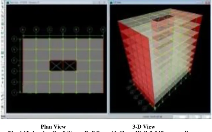
Plan View 3-D View
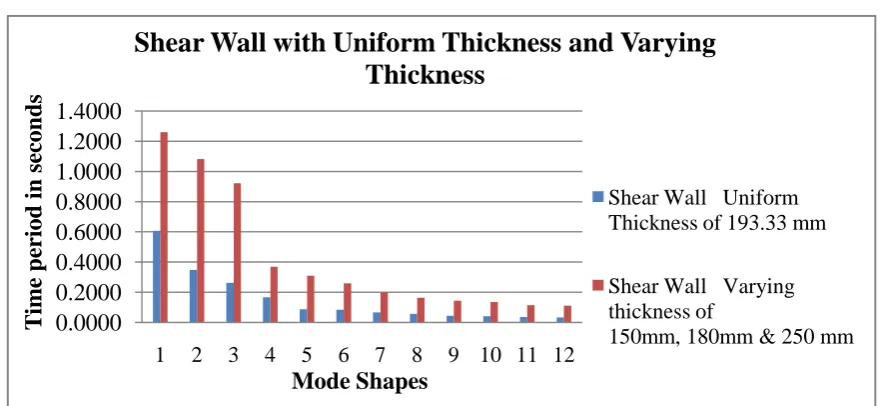
Fig. 4.12 showing G + 9 Storey Building with Shear Wall & Lift core wall Table 4.5 Shear wall with uniform thickness and varying thickness
Uniform Thickness of 193.33 mm Varying thickness of 150mm, 180mm & 250 mm
1 0.6045 0.5997
2 0.3409 0.3156
3 0.2577 0.2360
4 0.1727 0.1724
5 0.0890 0.0890
6 0.0852 0.0828
7 0.0658 0.0635
8 0.0614 0.0613
9 0.0477 0.0476
10 0.0414 0.0418
11 0.0400 0.0399
12 0.0353 0.0352
Fig.4.13 Shear wall with Uniform Thickness and Varying Thickness
Table 4.6 Response Spectrum Base reactions – Shear wall without openings/with openings RESPONSE SPECTRUM BASE REACTIONS - SHEAR WALL WITH NO OPENINGS Spec Mode F1 F2 F3 M1 M2 M3 EQX 1 717.78 0.00 0.00 0.00 519440 -211678 EQY 2 0.00 1030.61 0.00 -762889 0.00 486901
RESPONSE SPECTRUM BASE REACTIONS - SHEAR WALL WITH OPENINGS Spec Mode F1 F2 F3 M1 M2 M3 EQX 1 714.98 0.00 0.00 0 517569.8 -210853 EQY 2 0.00 1054.07 0.00 -772973 0 497988
Result of analysis done on Shear wall with/without openings showing base reactions and moment distribution are displayed in Table 4.6. Of all mode shapes, mode shape 2 has the maximum base reaction force for the building with openings in shear wall/without any openings in shear wall.
0.0000
0.2000
0.4000
0.6000
0.8000
1.0000
1.2000
1.4000
1
2
3
4
5
6
7
8
9
10 11 12
T
im
e p
er
iod
in
sec
on
d
s
Mode Shapes
Shear Wall with Uniform Thickness and Varying
Thickness
Shear Wall Uniform
Thickness of 193.33 mm
Shear Wall Varying
thickness of
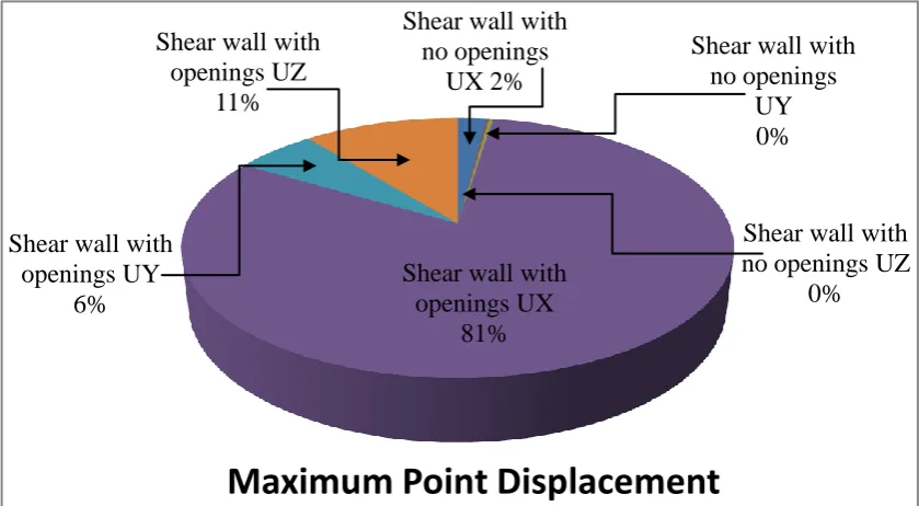
Fig.4.14 Point displacement in X, Y & Z Directions
Table 4.7 represents the storey deflection in X, Y & Z directions under seismic loads for Shear walls with/without
openings. The maximum storey displacement of the building occurs in the 9th storey. The corresponding pie graph of
Table 4.7 is shown in Fig. 4.14. We infer that point displacements in all 3 directions are comparatively high in shear wall with openings.
Table 4.8 Various Modes and the corresponding period in Seconds
Mode shapes Openings in Shear wall Shear Wall without Openings 2nd Storey 4th Storey 6th Storey 8th Storey
1 0.6049 0.6043 0.6033 0.6020 0.6038 2 0.3967 0.3887 0.3812 0.3760 0.3763 3 0.3023 0.2948 0.2881 0.2829 0.2839 4 0.1723 0.1717 0.1721 0.1721 0.1721 5 0.1021 0.0957 0.0964 0.0965 0.0941 6 0.0884 0.0887 0.0884 0.0887 0.0886 7 0.0807 0.0739 0.0749 0.0749 0.0728 8 0.0611 0.0611 0.0612 0.0612 0.0612 9 0.0475 0.0491 0.0475 0.0482 0.0475 10 0.0467 0.0475 0.0464 0.0475 0.0459 11 0.0399 0.0402 0.3990 0.0399 0.0399 12 0.0367 0.0393 0.0364 0.0384 0.0359
Deformation (mode shape) for Shear wall with/without openings for different storey‟s is shown in Tabular form above in Table 4.8 and as a 3D graph in Fig. 4.15. Deformation is peak at mode shape 1 and gradually becomes less for mode shape 12 & there is not much difference in the time periods between shear wall with openings/without openings. Openings in shear wall increases the stress and reduces the stability.
Shear wall with
no openings
UX 2%
Shear wall with
no openings
UY
0%
Shear wall with
no openings UZ
0%
Shear wall with
openings UX
81%
Shear wall with
openings UY
6%
Shear wall with
openings UZ
11%
.
Fig. 4.15 3D Line Graph showing Mode Shapes Vs. Time period for Shear Wall with openings (2, 4, 6, 8Stories) / without openings
V.
CONCLUSION5.1 Conclusion
From the results it is inferred that shear walls are more resistant to lateral loads in regular/Irregular structure. The moments in the columns got reduced when shear wall is introduced in the structure. The maximum storey displacement of the building is reduced by 50% when shear wall is provided. Mode shape 2 shows the highest deformed shape. Shear wall with openings and with varying thickness is still strong & stable enough to resist seismic loads. For safer design, the thickness of the shear wall should range between 150mm to 400mm.
5.2 Discussion
Provision of shear wall results in a huge decrease in base shear and roof displacement both in symmetrical building and un-symmetrical building. It is observed that in the regular frame, there is no torsional effect in the frame because of symmetry. In an irregular frame, there is torsional rotation in the structure. Shear walls in buildings must be symmetrically located in plan to reduce ill-effects of twist in buildings. They should be placed symmetrically along one or both directions in plan. Shear walls are more effective when located along exterior perimeter of the building – such a layout increases resistance of the building to twisting. A shear wall elevator core can provide a major part of the bending and torsional resistance in a building structure.
ACKNOWLEDGEMENTS
The author expresses her sincere thanks and gratitude to Dr. R. ANNADURAI, Professor and HOD,
Department of Civil Engineering, for the valuable suggestions and advice in carrying out this thesis work. The author hereby acknowledges with deep sense of gratitude the valuable guidance, moral support and encouragement given by
the Project Coordinators / Structural Engineering (Department), Dr. K. S. SATYANARAYANAN, Professor and also
Mr. G. AUGUSTINE MANIRAJ PANDIAN, Professor, Department of Civil Engineering. The author expresses her 0.0000 0.1000 0.2000 0.3000 0.4000 0.5000 0.6000 0.7000
1 2 3 4 5 6 7 8
9 10 11 12
T im e perio d in
S
ec
on
d
s
Mode Shapes
Mode shapes Vs. Time period for Shear walls
with openings/without any openings
Opening in Shear wall at 2nd Storey
Opening in Shear wall at 4th Storey
Opening in Shear wall at 6th Storey
Opening in Shear wall at 8th Storey
sincere thanks & gratitude to her guide Mr. S. MANIVEL, Asst. Professor (OG), for guidance, motivation and encouragement given during the course of this project.
The author expresses her gratitude to the Class in-charge Mr. R. RAMASUBRAMANI, Asst. Professor (OG),
for all the help rendered during the course of this project.
The author is indebted to all the Faculty Members of the Department of Civil Engineering (SRM) for the moral support extended to her during the course.
REFERENCES
[1] Venkata Sairam Kumar.N, Surendra Babu (2014), „Shear walls – A Review‟. IJIRSET, ISSN: 2319 - 8753, Vol. 3, Issue 2, February 2014 [2] Ravikanth Chittiprolu, Ramancharla Pradeep Kumar, „Significance of Shear wall in High rise Irregular Buildings‟, IJEAR Volume 4, Issue SpL-2, Jan – June 2014.
[3] Varsha R. Harne (2014), „Comparative Study of Strength of RC Shear wall at different location of Multi- storied Residential Building‟, International Journal of Civil Engineering Research ISSN 2278-3652,Volume 5, Number 4 (2014), pp. 391-400.
[4] Shaikh Abdul Aijaj Abdul Rahman (2013), „Seismic Response of Vertically Irregular RC Frame with Stiffness Irregularity at Fourth Floor‟, International Journal of Emerging Technology & Advanced Engineering ISSN 2250-2459, Volume 3, Issue 8 (2013).
[5] J. V. Sunil Ganesh & Mallikarjun S. Bhandiwad (2014) , „Seismic Analysis of Irregular Multi-storied structure with Shear wall‟, The International Journal of Science & Technoledge, Vol. 2, Issue 6.
[6] Y. M. Fahjan & J. Kubin & M. T. Tan (2010), ‟Nonlinear Analysis Methods of Reinforced Concrete Buildings with Shear walls„, ECEE. [7] G. Nandini Devi, K. Subramanian & A.R. Santhakumar (2009) , „Structural Response of Multibay Multi-storey Lateral Load Resisting Systems under Seismic type loading„, International Journal of Earth Sciences and Engineering, ISSN 0974 - 5904, Vol. 02, NO. 02, pp. 145-153.
[8] J. Kubin, Y.M.. Fahjan and M.T.Tan [(2008), „Comparison of Practical Approaches for Modelling Shear walls in Structural Analyses of Buildings‟, The 14th World Conference on Earthquake Engineering October 12- 17, Beijing, China.
[9] N.S. Potty, W.A. Thanoon, H.H Hamzah , A.M. M Hamadelnil (2008) , ‟ Practical Modelling Aspects for Analysis of Shear walls using Finite Element Method‟, ICCBT, Malaysia.
[10] Devesh P. Soni & Bharat B. Mistry (2006) , „Qualitative Response of Seismic Response of Vertically Irregular Building Frames‟, SVIT, Vasad.
BIOGRAPHY
Name : HEMA MUKUNDAN
Affiliation : P.G Student (M. Tech – Structural), Department of Civil Engineering, SRM University, Kattankulathur – 603 203
Interest Area : Structural Dynamics, Design of Tall Buildings & Steel structures