ISSN(Online): 2319-8753 ISSN (Print): 2347-6710
International Journal of Innovative Research in Science,
Engineering and Technology
(A High Impact Factor, Monthly, Peer Reviewed Journal) Visit: www.ijirset.com
Vol. 7, Issue 7, July 2018
Bandwidth Enhancement of Compact Slot
Loaded Rectangular Microstrip Patch
Antenna using IE3D
Dheeraj Tripathi1, D. K. Srivastava2 and Ramesh Kumar Verma3
PG Student, Department of Electronics & Communication Engineering, Bundelkhand Institute of Engineering & Technology, Jhansi, UP, India1
Professor, Department of Electronics & Communication Engineering, Bundelkhand Institute of Engineering & Technology, Jhansi, UP, India2
Research Scholar, Department of Electronics & Communication Engineering, Bundelkhand Institute of Engineering & Technology, Jhansi, UP, India3
ABSTRACT:In this research paper, a compactmicrostrip patch antenna had been design and analyzed. The proposed
antenna get the required impedance bandwidth is 77.85%. The design antenna has resonant frequency of 2.2GHz.The bandwidth enhanced by changing parameters of rectangular microstrip patch antenna. The variation made in the design structure antenna is cut different slot on patch and simulate the result of design structure. The proposed antenna is used for band (2.057GHz to 4.679GHz) suitable for wireless communication. A line feed of 50Ω is introduced to the given rectangular shape radiating patch antenna. The antenna is suitable for application such as Mobile satellite services 2.2GHz is realized.
KEYWORDS: Compact, Bandwidth, Patch, Rectangular,Radiating, Wireless. Line feed.
I. INTRODUCTION
ISSN(Online): 2319-8753 ISSN (Print): 2347-6710
International Journal of Innovative Research in Science,
Engineering and Technology
(A High Impact Factor, Monthly, Peer Reviewed Journal) Visit: www.ijirset.com
Vol. 7, Issue 7, July 2018
II. BASIC PARAMETERS FOR ANTENNA DESIGN
For calculation of dimension of antenna, several parameter which are resonant frequency (fr), substrate thickness (h),
loss tangent (tanδ), and dielectric constant (ɛr) [10] given in table 1
Table 1: Antenna design specifications
S.No. Antenna Parameter Values
1 Design Frequency (fr) 3.3GHz
2 Substrate thickness (h) 1.6 mm 3 Dielectric constant (ɛr) 4.4
4 Loss tangent ( tan δ ) 0.001
III. GEOMETRY OF PROPOSED ANTENNA DESIGN
In the design of proposed antenna we make firstly design of a rectangular patch with calculated dimension of patch and ground plane and make design on the patch. Dimensional parameters of proposed antenna are list below table 2. Then we cut a slot on rectangular patch like a mirror image of c shape after this we measure the gain, return loss and all other parameters then we cut another slot by its corner of shape and again measure all parameters, finally we cut a slot from other edge corner and noted down all parameters. By operating this way the resonant peak shifted towards lower frequency side and as a result the bandwidth has been enhanced.
Table 2: Calculated dimensions of proposed antenna
S.No Antenna Dimension Values(mm)
1 Ground Length (Lg) 30.84 2 Ground Width (Wg) 37.26 3 Patch Length (Lp) 21.24 4 Patch Width (Wp) 27.66
Initially, a conventional antenna of length 21.24mm and width 27.66mm radiating patch has been design with ground plane of length 30.84mm and width 37.26mm. After designing ground plane and patch, a rectangular notch of 10.62mm x 13.83mm is cut from its left edges at coordinate (10.11mm, 18.63mm) and a line feed of 50Ω is applied at
ISSN(Online): 2319-8753 ISSN (Print): 2347-6710
International Journal of Innovative Research in Science,
Engineering and Technology
(A High Impact Factor, Monthly, Peer Reviewed Journal) Visit: www.ijirset.com
Vol. 7, Issue 7, July 2018
Fig.1 Geometry of proposed antenna with notch
The proposed antenna is simulated between 1GHz to 5GHz. The design antenna is resonating at 2.38GHz with lower frequency about 2.14GHz and higher frequency about 2.86GHz. Bandwidth is come 28.69% with return loss is -19.147dB. S parameter display and VSWR display are shown in fig. 1(a) and fig. 1(b).
ISSN(Online): 2319-8753 ISSN (Print): 2347-6710
International Journal of Innovative Research in Science,
Engineering and Technology
(A High Impact Factor, Monthly, Peer Reviewed Journal) Visit: www.ijirset.com
Vol. 7, Issue 7, July 2018
Fig 1(b) VSWR display
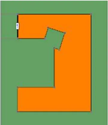
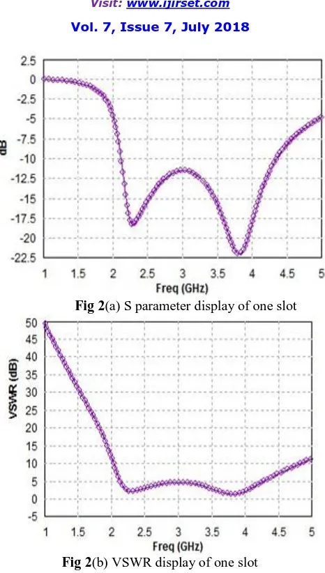
After this, a slot of dimension5mm x 5mm is cut at coordinate (15.275mm, 25.5mm) in the rectangular notch. The geometry of proposed antenna with first slot is shown in fig 2. By introducing this slot, the bandwidth is come 68.33 %, with the resonant frequency 3.814 GHz. The lower frequency is about 2.133GHz and higher frequency is about 4.347GHz and return loss is -22.00dB and S parameter display and VSWR display are shown in fig. 2(a) and fig. 2(b)
ISSN(Online): 2319-8753 ISSN (Print): 2347-6710
International Journal of Innovative Research in Science,
Engineering and Technology
(A High Impact Factor, Monthly, Peer Reviewed Journal) Visit: www.ijirset.com
Vol. 7, Issue 7, July 2018
Fig 2(a) S parameter display of one slot
Fig 2(b) VSWR display of one slot
ISSN(Online): 2319-8753 ISSN (Print): 2347-6710
International Journal of Innovative Research in Science,
Engineering and Technology
(A High Impact Factor, Monthly, Peer Reviewed Journal) Visit: www.ijirset.com
Vol. 7, Issue 7, July 2018
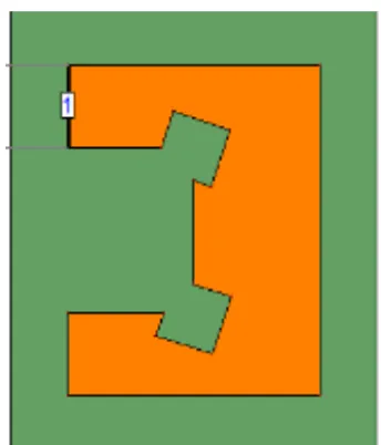
Fig 3 Geometry of proposed antenna with two slots
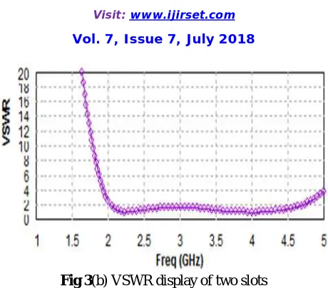
By introducing second slot, the bandwidth is come 77.85%, with the resonant frequency 2.2GHz. The lower frequency is about 2.057GHz and higher frequency is about 4.679GHz and return loss is -53.835dB and S parameter display and VSWR display are shown in fig. 3(a) and fig. 3(b)
ISSN(Online): 2319-8753 ISSN (Print): 2347-6710
International Journal of Innovative Research in Science,
Engineering and Technology
(A High Impact Factor, Monthly, Peer Reviewed Journal) Visit: www.ijirset.com
Vol. 7, Issue 7, July 2018
Fig 3(b) VSWR display of two slots
The comparative analysis of all three antennas with rectangular notch, one slot and two slots are shown in table 3
Table 3: Compression between different slots
IV. SIMULATION AND DISCUSSION
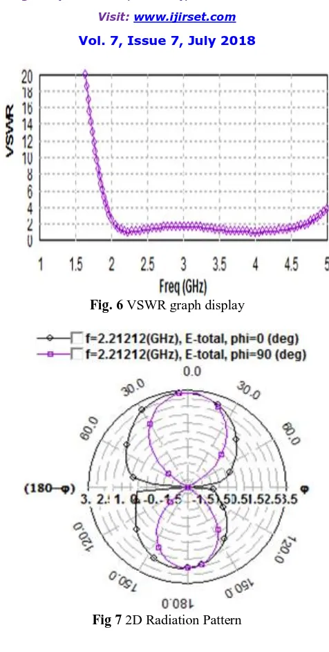
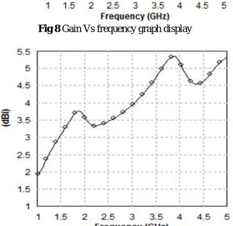
By designing software IE3D simulation software, the performance of proposed microstrip patch antenna is analyzed at resonant frequency of 2.22GHz. Final configuration of proposed antenna is shown in fig. 4. Simulation results of return loss, VSWR, 2D radiation pattern, gain, antenna efficiency and directivity are plotted for the range of frequency 1GHz to 5GHz. Calculate fractional bandwidth of proposed antenna is 77.85 % which lies between 2.057 GHz to 4.679GHz band and return loss is -53.88dB at resonance frequency 2.22 GHz has been obtained.
ISSN(Online): 2319-8753 ISSN (Print): 2347-6710
International Journal of Innovative Research in Science,
Engineering and Technology
(A High Impact Factor, Monthly, Peer Reviewed Journal) Visit: www.ijirset.com
Vol. 7, Issue 7, July 2018
Fig. 4 Geometry and dimension of the proposed Antenna
ISSN(Online): 2319-8753 ISSN (Print): 2347-6710
International Journal of Innovative Research in Science,
Engineering and Technology
(A High Impact Factor, Monthly, Peer Reviewed Journal) Visit: www.ijirset.com
Vol. 7, Issue 7, July 2018
Fig. 6 VSWR graph display
ISSN(Online): 2319-8753 ISSN (Print): 2347-6710
International Journal of Innovative Research in Science,
Engineering and Technology
(A High Impact Factor, Monthly, Peer Reviewed Journal) Visit: www.ijirset.com
Vol. 7, Issue 7, July 2018
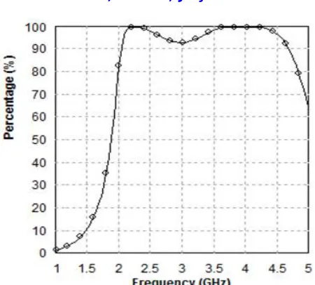
Fig 8 Gain Vs frequency graph display
ISSN(Online): 2319-8753 ISSN (Print): 2347-6710
International Journal of Innovative Research in Science,
Engineering and Technology
(A High Impact Factor, Monthly, Peer Reviewed Journal) Visit: www.ijirset.com
Vol. 7, Issue 7, July 2018
Fig 10 Efficiency Vs frequency graph display
V. CONCLUSION
A rectangular patch antenna which resonating 2.2 GHz frequency and used for MSS (Mobile satellite services) application and mobile satellite communication. IE3D simulation software used for simulation purpose the bandwidth is enhanced of a rectangular patch antenna. In compression of all three slot cut in patch, there is difference occur in BW. The BW of antenna is enhanced from 28.69% to 77.85%. Return loss of antenna also increased from 19.147 to -53.838 dB. The result of antenna gain is come 3.3269dB and Directivity is 3.32735dB. The 3dB beam width is (79.5397, 152.895) deg and antenna efficiency is 99.9894%.
REFERENCES
[1] Loutfi Nuamyi "WiMAX Technology for Broadband Wireless Access by WILEY publications
[2] A. B. Nandgaonkar and S. B. Deosarkar, “Broadband stacked patch antenna for Bluetooth applications”, Journal of Microwaves, Optoelectronics and Electromagnetic Application, vol. 8, no. 1, pp. 1-5, 2009
[3] R. Q. Lee and K. F. Lee, “Experimental study of the two-layer electromagnetically coupled rectangular patch antenna”, IEEE Trans. Antennas and Propagation, vol. 38, pp. 1298-1302, August 2006
[4] R. L. Yadava and B. R. Vishvakarma, “Analysis of electromagnetically coupled two-layer elliptical microstrip stacked antennas”, International Journal of Electronics, vol. 87, no. 8, pp. 981-993, 2000
[5] S. Egashira and E. Nishiyama, “Stacked microstrip antenna with wide bandwidth and high gain”, IEEE Trans-actions on Antennas and Propagation (USA), vol. 44, no. 11, pp. 1533-1534, 1996
[6] D. M. Pozar and D. H. Schaubert, “Microstrip antennas: the analysis and design of microstrip antennas and arrays”, IEEE Press, 1995 [7] Kumar G., & Ray K. P., Broadband Microstrip Antennas” Artech House, 1-58053-244-6, 2003.
[8] K. Shambavi, ‟Gain and bandwidth enchancement technique in square microstrip antenna for WLAN applications”, Proceedings of Asia-Pacific Microwave Conference, 2007
[9] Xiao Zhang,and Lei Zhu,“Gain-enhanced patch antennas with loading of shorting pins" IEEE Transactions on Antennas and Propagation 0018-926X (c) 2016 IEEE.
[10] Ramesh Kumar Verma and D.K.Srivastava, “Compact square microstrip patch antenna loaded with notch for radar applications”, International Journal of Advance Engineering and Research Development, Vol.4, Issue.10, October 2017