Three Phase Grid Connected Photovoltaic
System with MPPT Technique Based on
Voltage Oriented Control Using Average
Current Mode Controller
B.Karthik1, T.Devi2
Assistant Professor, Dept. of EEE, Sona College of Technology, Salem, Tamilnadu, India1
PG Student [PSE], Dept. of EEE, Sona College of Technology, Salem, Tamilnadu, India2
ABSTRACT: This paper presents a Matlab/Simulink model of grid connected photovoltaic (PV) system, including a PV array, a maximum power point tracking boost converter and a grid interactive, a control system. A space vector pulse width modulation (SVPWM) has been widely applied in the current control of three-phase voltage source inverters (VSI). The proposed system consists of two main controllers: a boost converter and a grid interactive voltage source inverter. The boost converter is used to regulate the PV voltage and track the MPP of PV array. A perturbation and observation (P&O) is used as MPPT method and it determines the system operation point according of rapidly changing atmospheric conditions. A cascaded control structure with an outer dc link voltage control loop and an inner current control loop is used. The currents are controlled in a synchronous orthogonal d, q frame using a decoupled feedback control. The reference current of proportional–integral (PI) d-axis controller is extracted from the dc-side voltage regulator by applying the energy balancing control. Furthermore, in order to achieve a unity power factor, the q-axis reference is set to zero.the average current mode control of a grid connected inverter is investigated. Two control loops are used: the outer one controls the power flow from the source generator to the grid and the inner one controls the grid currents. This control method is applied to two system configurations with di erent filter cells, L- and
LCL-filter. The comparison shows the e ectiveness of the last configuration in terms of harmonics rejection. Simulations of
the proposed method show performances in both transient and steady state.
KEYWORDS: grid-connected photovoltaic system, Maximum Power Point Tracking (MPPT), average current mode controller(ACMC), Boost converter, Proportional-Integral (PI) control, voltage oriented control VOC.
I.INTRODUCTION
The characteristic voltage and power of a photovoltaic (PV) array is nonlinear and time varying because of the changes caused by the atmospheric conditions, a maximum power point tracking algorithm is adopted to maximize the output power. In recent years, the grid connected PV systems have become more popular because they do not need battery backups to ensure MPPT [13]. The two typical configurations of a grid-connected PV system are single or two stages. In two stages, the first is used the conversion of this power into high-quality ac voltage, the second to boost the solar array voltage and track the maximum power. The presence of DC/DC converter allows to maintain the fixed DC link voltage enough high to make the inverter operate. Although there is much information in the literature [1], development of dynamic models of grid-connected PV systems are including a PV array, a control system using PI, a distribution network and a load, a PWM technique. Reference [12], a sliding mode controller for the threephase grid-connected photovoltaic system the proposed system consists of maximum power point tracker (MPPT) and sliding mode current controller with PWM control inverter, the experimental results verify the validity of the proposed controller. In [3], a technique for improving P&O MPPT performances of double-stage grid-connected photovoltaic systems and experimental measurements confirm the effectiveness of the proposed approach.
controllers; the DC-side controller for the boost DC/DC converter, and AC-side controller for the inverter. The DC/DC converter is controlled to maintain the fixed DC link voltage enough high to make the inverter operate, to achieve the maximum power from the PV array. Many algorithms have been developed for the MPPT of a PV array [1,5,15]. A perturbation and observation (P&O) method is applied for the maximum power point tracking (MPPT) controller, the MPPT techniques is most popular because of the simplicity of its control structure. ACMC is a current control technique that has an almost constant frequency and produces a user-defined current waveform. It has a fast response
time and is capable of supporting a wide range of power circuit topologies. ACMC is based on a compensator circuit which compensate the poles of an integrating filter transfer function. It uses this integrating filter to produce an average
current error signal that is compared to a triangular waveform to produce the required pulse width modulation signal [2].
II. SOLAR CELL AND PV ARRAY MODEL
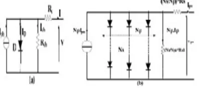
The equivalent-circuit model of PV is shown in Fig. 2(a). In this model, it consists of a light-generated source, a diode, series and parallel resistances [2]. The terminal equation voltage-current characteristic equation of a solar cell is given by:
I ph − I s q exp q (V + RsI ) / AKT………...(1)
Where I and V are the cell output current and voltage, Iph: is photocurrent, Is: is the reverse saturation current, n is the diode factor, q is the electron charge (q=1.6 10-19C), K: the Boltzmann’s constant (K=1.38 10-23), and T is the solar array panel temperature, Rs: is the intrinsic series resistance of the solar cell, Rsh: is the equivalent shunt resistance. A PV array is a group of several PV modules which are electrically connected in series and parallel circuits to generate the required current and voltage. The equivalent circuit for the solar module arranged in Np parallel and NSseries is shown in Fig. 2(b) and the terminal equation for the current and voltage of the array becomes as follows:
I = NpIph − NpIsexpq(V / Ns + RsI / Np ) / KTA) −1 −( NpV / Ns + RsI ) / Rsh……….(2)
Where Np represents the parallel number of module. Note that each module is composed of Ns series number of cells of a PV array
Fig. 1. Equivalent circuit model of solar cell (a)/array (b).
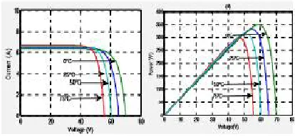
Fig. 2. (a) I-V characteristics and (b) P-V characteristics of the PV module at constant temperature T=25°C under different irradiance levels G=250,500,750,1000W/m2.
Fig. 3. (a) I-V characteristics and (b) P-V characteristics of the PV module at constant insolation G=1000W/m2 and different temperature T= 0°C,25°C,50°C,75°C
Fig. 4(a) P-V characteristics and (b) I-V characteristics of the PV array at STC (T=25°C, G=1000W/m2)
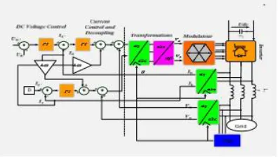
III. PROPORTIONAL-INTEGRALE CONTROL A. voltage control
The block diagram of dc-link voltage control is shown in Fig. 7, where Ru(s) is a proportional-integral
compensator. It is the processed by an error signal between reference voltage and the actual DC voltage output boost converter.
U(S)=Kup+Kuits
The closed-loop transfer of DC link voltage regulation, obtained from Fig. 7, has the following form
∗ = ……….(3)
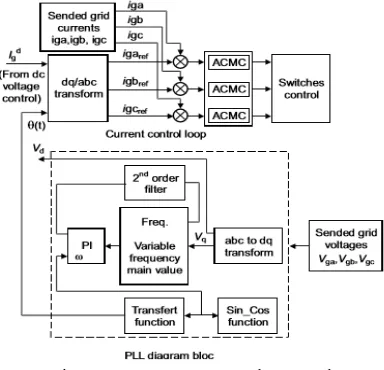
B. Current Control
The diagram of the current regulator is shown in Fig. 8. The current controller is designed with two control loops for active and reactive power controls [8]. The PI current controller Ri (s) in the d-q reference frame is defined as:
The voltage regulator parameters can be given as follows
∁) ………(4)
Where, kip and kii are the proportion coefficient and integral coefficient, respectively
The closed-loop transfer of the d-q current loops, obtai0ned from Fig. 8, has the following form:
( )
∗( )= ( )
∗( )= = ……….(5)
IV. AVERAGE CURRENT MODE CONTROL
A wide range of power conversion applications use the current control technique. This technique controls the peak inductor current to regulate the converter output.
The most drawbacks of current control are a poor noise immunity and instability at duty ratios exceeding 0.5. The Average Current Mode Control (ACMC) is a control technique that overcomes problems listed above. ACMCis a two-loop technique that uses an integrator in the inner two-loop to average the sensed current. ACMC description and its standard design are presented in [2]. A circuit scheme that could be used to implement ACMC is shown in Fig. 8. The current to be controlled is sensed through RS and averaged. The voltage reference Vref is delivered by the outer loop. The integrator output is compared to a triangular waveform, the switch control is then generated. The transfer function of the integrator circuit [4] is described by equation
= + ( − )
( . . )…...(6)
Where =
Fig 8 average current mode control
V. SIMULATION RESULT
The rated power, AC voltage level, filters parameters and frequencies switching used in this simulation arelisted below.
Rated power: 1 KW Voltage (RMS): 220 V
L-filter:
Inductance (L, r): 10 mH, 1Ω
Frequency switching: 10 KHz
LCL-filter:
Converter side inductance (L1, r1): 2 mH, 0.2Ω
Grid side inductance (L2, r2): 1 mH, 0.1Ω
Capacitor (C, rd): 5µF, 5Ω
A. DC-link Voltage regulation
Figure 8 shows the DC-link voltage result. It is regulated and reaches closely the voltage reference after a small rise time compared to the grid period. Furthermore, in actual case, the DC-link capacitor should be charged before starting the system.
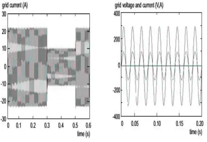
B. VSI and Grid currents
VI.CONCLUSION
In this paper,averagecurrent mode control for three phase grid connected DC/AC converters offers an excellent steady-state response featured by precise control with zero steadysteady-state error, very fast dynamic response, highly sinusoidal waveform., voltage, although the grid voltage has a low-order harmonic distortion. As well as the convenient active and reactive power decoupled controls. The sliding mode control has excellent robustness with nominal inductance varied from 33% of the actual value.
REFERENCES
[1] Rujia Men, Xiaoqing Han, “ Optimum Control and Simulation for a Grid- Connected Photovoltaic System, ” IEEE 11th International conference on, pp. 431-435, 2010.
[2] Hui Zhang, Hongwei Zhou, Jing Ren1, Weizeng Liu, ShaohuaRuan and YongjunGao, “ Three-Phase Grid-Connected Photovoltaic System with SVPWM Current Controller, ” IEEE 6th International conference IPEMC, pp. 2161- 2164, 2009.
[3] Nicola Femia, Giovanni Petrone, Giovanni Spagnuolo, Massimo Vitelli, “ A Technique for Improving P&O MPPT Performances of Double-Stage Grid-Connected Photovoltaic Systems,” IEEE Transactions on Industrial Electronic,Vol.56.No.11, pp. 4473-4481, November 2009.
[4] Mustapha Raou, MoulayTaharLamchich., “ Average Current Mode Control Of A Voltage Source Inverter Connected To The Grid: Application To Different Filter, ” Journal of Electrical Engineering, Vol. 55, No, pp. 77-82, 2004.
[5] Nilesh Shah, R. Chudamani, “Single-Stage Grid Interactive PV System Using Novel Fuzzy Logic Based MPPT with Active and Reactive Power Control, ” IEEE Conference on Industrial Electronics and Applications (ICIEA) , pp. 1667-1672, 2012.
[6] ShamsodinTaheri, HamedTaheri b, Zainal Salam ,KashifIshaque , and HosseinHemmatjou , “Modified Maximum Power Point tracking (MPPT) of Grid-Connected PV system under Partial Shading Conditions, ” IEEE Canadian Conference on Electrical and Computer Engineering (CCECE), 2012.
[7] H. El Fadil, F. Giri, J.M. Guerrero, “Grid-Connected of Photovoltaic Module Using Nonlinear Control,” IEEE International Symposium on Power Electronics for Distributed Generation Systems (PEDG), pp. 119-124, 2012.
[8] Youngroc Kim, Hanju Cha, Byeong-Mun Song, Senior Member and Kwang Y. Lee, Fellow, “Design and Control of a Grid-Connected Three- Phase 3-Level NPC Inverter for Building Integrated Photovoltaic Systems,” IEEE PES, pp. 1-7, 2011.