Control and Design of a Direct
Double-Frequency Ripple Current Control by using
Fuzzy Logic Control Strategy
N.S.Pavani1, N.Harathi2
Assistant Professor, Dept. of EEE, Annamacharya Institute of Technology & Sciences, Tirupati, A.P.,
India
1PG Student [PE&ED], Dept. of EEE, Annamacharya Institute of Technology & Sciences, Tirupati, A.P.,
India
2ABSTRACT: This project proposes a direct double-frequency ripple current control in a single-phase high-power fuel cell converter that can accomplish low-frequency ripple-free input current without using large electrolytic capacitors. Such a ripple current may reduce fuel cell life span. It tends to decrease the fuel cell output capacity because the fuel cell controller trips under instantaneous over-current condition. In this proposed method the content of ripples in current is reduced without requirement of extra switching devices. A fuel cell power system that contains a dc–ac inverter tends to draw an ac ripple current at twice the output frequency. Such a ripple current may reduce input cell lifespan an advanced active control method is proposed to incorporate a current control loop in the dc–dc converter for ripple reduction. To remove the double-frequency ripple current disturbance lead by the single-phase inverter load, a proportional–resonant controller and fuzzy controller is developed to accomplish an extra high control gain at designed resonant frequency. This will reduce both size and cost of the system. The system is designed and simulated using MATLAB/ Simulink Software.
KEYWORDS-Current-fed three-phase dc–dc converter, direct double-frequency ripple current control, electrolytic capacitor free, fuel cell, zero voltage switching (ZVS).
I. INTRODUCTION
Fuel cells are recognized as a future source of generating energy due to their efficient and clean energy characteristics, they produce low-varying dc voltage in the range of 30 to 60V for static power application such as residential usage. For static fuel cells, the power conditioning system consists of a low-voltage fuel cell as the primary source, a dc/dc converter to accomplish isolated high voltage, and a dc/ac inverter to connect commercial ac voltage. A dc/ac inverter supplies power into a 220V ac utility, an isolated dc/dc converter has to convert low varying dc voltage to high constant dc voltage about 370V. Therefore, a dc/dc converter with a high voltage ratio is needed, and a transformer is normally employed for boosting voltage as well as isolation. However, high leakage inductance in the transformer leads to voltage spikes and electromagnetic noise. In order to accomplish a high voltage ratio while limiting the overshoot in the turn-off voltage produced by the leakage inductance, a current-fed dc/dc converter with an active clamp has been hosted in the push–pull topology and full-bridge topology for all single–phase application. In addition, a soft-switching active clamp scheme has been suggested to minimize turn-off losses in the clamp switch. These converters have been displayed to perform pretty well, but the single-phase circuits face severe components stress and degraded efficiency for higher power levels.
A.LITERATURE SURVEY
B. DC-DC CONVERTER
In many industrial applications, it is required to converter a fixed dc source into a variable voltage dc source. A dc-dc converter converts directly from dc-dc and simply known as a dc converter. A dc converter can be considered as dc equivalent to an ac transformer with a endlessly variable turn’s ratio. Like a transformer, it can be used to step down or step up a dc voltage source. Dc converters can be used as switching-mode regulators to convert a Dc voltage, normally unregulated to a regulated dc o/p voltage. This regulation is normally achieved by PWM at a fixed frequency and the switching device is normally BJT MOSFET IGBT. The designer can select the switching frequency by choosing the value of R, L, and C of frequency oscillator.
II. PROPOSED METHOD
A. PROPOSED CONVERTER TOPOLOGY AND OPERATION ANALYSIS
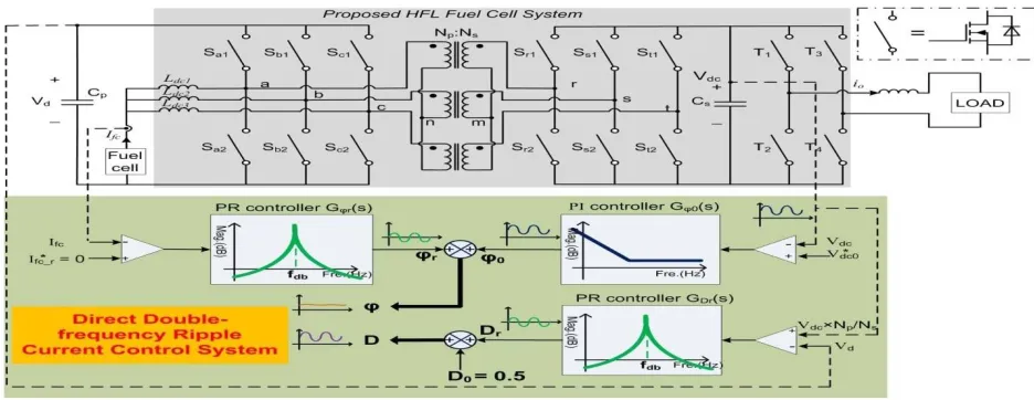
This paper presentstwo-stageHFL-basedhigh-power fuel cell system shows in Fig 1. The system consists of a current-fed 3- phase HFL converter with an isolated Y-Y connected high- frequency (HF) transformer and an inverter. Thephaseshiftangle ϕ controls the three-phase HFLconverterpowerflowbetween the active switches on the low-voltage side (LVS) andthehigh-voltageside(HVS).Theconvertercanbefunctioned either in the boost mode or in the buck mode. In this proposed method, the converter is operated in boost mode for fuel cell application. The boost function is achieved by the dc inductors (Ldc1, Ldc2, and Ldc3) and three half-bridges on the LVS. The leakage inductors (Ls1,
Ls2, and Ls3) are the energy transfer element for eachphase. This research focus is to study the direct double-frequency ripple current control of this three-phase HFL converter while connecting a single-phase inverter load.
Fig. 1 Proposed direct double-frequency ripple current control system diagram
B. DIRECT DOUBLE-FREQUENCY RIPPLE CURRENT CONTROL SYSTEM DESCRIPTION
III. FUZZY LOGIC CONTROLLER
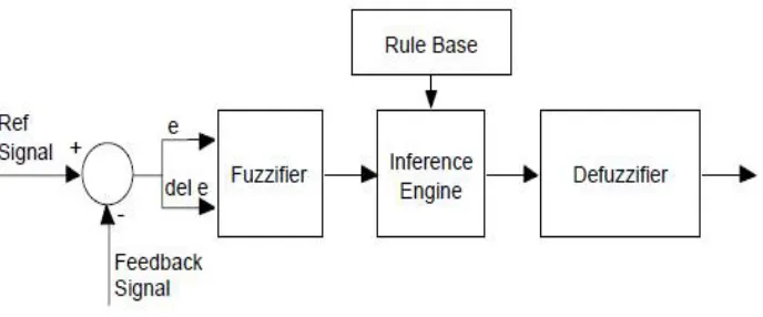
Fuzzy Logic Controller (FLC) is a fuzzy logic based control system, it is a non-mathematical decision algorithm that is based on an operator’s experience. This controller analyses analog input value in terms of logical variables that can take on continuous values between 0and 1.The First inputs of the Fuzzy Logic Controller is error and second input is change in error. Fig.2 shows the Fuzzy logic controller.
Fig.2 Show the Structure of Fuzzy Logic Controller.
Fig 2 shows the structure of fuzzy logic controller there are four basic elements in the fuzzy controller system structure there are fuzzifier, rule base, inference engine and defuzzifier. Input output control passes through a pre-processor while output passes through a post-pre-processor
1. FUZZIFIER:
Linguistic variables used by Fuzzy Logic instead of numerical variables. The process of changing a numerical value into a linguistic label is called “Fuzzification”. For closed loop control system, the error (e) between the reference voltage and the output voltage, and the rate of change of error (Del e) can be named as zero (ZE), positive small (PS), negative small (NS), etc.
2. INFERENCE:
In conventional PI controllers having control laws, whereas the Fuzzy Controller contains rules. Rules are linguistic in nature and they permit the operator to develop a control design in a more familiar human environment. A typical rule can be written as below: The member ship functions are used to Fuzzy inputs shows in Fig 3. The membership value can take from 0 to 1 for every Linguistic label. For each of the input and output variables, the following seven Linguistic labels are given to the membership functions:
Fig.3 Show the Fuzzy Logic Rule table.
NS=Negative Small PL=Positive Large ZE=Zero
After the member ship functions are found for each linguistic label, an intelligent decision procedure can be made to sense what output should be, is called inference.
If the “error” is negative Large (NL), and the “rate of change of error” is negative Large (NL), then the output is positive large (PL). It is suitable when dealing with large number of inputs, to put rules.
The Fig 3 shows the rules done for large number of input combinations. After the rules are evaluated, from each of the output membership function having a membership arrange for a numerical value called crisp value called “DeFuzzification”.
3. DEFUZZIFICATION:
DeFuzzification plays a vital role in Fuzzy logic based control system. It is the last process of Fuzzy control system in which the Fuzzy inputs, to put rules. The Fig 3 shows the rules done for large number of input combinations. After the rules are assessed, from each of the output quantities defined for the output membership functions are mapped into a crisp number.
IV. EXTENSION METHOD
In order for the proposed converter to be used in fuzzy logic control strategy, the interleaving method applicable to the traditional high boost ratio dc–dc converter can be employed. This gives the advantages of reduce low ripple current and lower conduction losses.
V. SIMULATION ANALYSIS
Using MATLAB/Simulink software, simulation was performed. MATLAB is a high performance language for technical computing and it integrates programming in an easy environment.
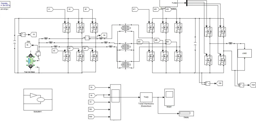
Fig.4 represents Simulink model of proposed high boost ratio transformer dc-dc converter. In this input voltage=51v given to this converter. The voltage is stepped up using a three phase transformer and the final DC voltage is obtained at the output side of the circuit
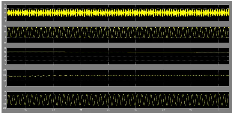
Fig. 5Simulation of results without the proposed control method, (A) Cp = 220 μF, Cs=3.18mF.
Above figure shows simulation results withoutthe proposed method. In order to suppress the fuel cell current double-frequency ripple, the large electrolytic capacitors are connected to the HVS dc bus. The adopted capacitors for this case are the following: Cp = 220 μF and Cs = 3.18 mF. As shown, Vd= 51 V, and Vdc = 200 V, and they both have relatively very small ripple due to the relatively large capacitor. ira_rms = 5.3 A andira_peak = 11.4 A.vo = 120 V (RMS).Ifc average value is around 41 A.
Fig. 6 Simulation of results without the proposed control method Cp=220μF, Cs=180μF.
7(A)
7(B)
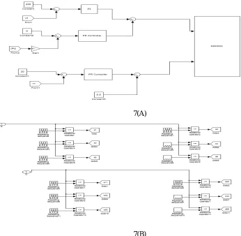
Fig. 7 Simulation arrangement for the proposed circuit control strategy
Fig.7 represents Simulink model of extension high boost ratio transformer dc-dc converter. In this input voltage=51v given to this converter. The voltage is stepped up using a three phase transformer, ripple currents will be generated. Controllers will reduce ripple currents and the fine DC voltage is obtained at the output side of the circuit.
Above figure shows simulation results with the proposed direct-ripple current control and d = 1 control is perfectly decoupled as designed. ira_rms = 5.9 A, and ira_peak = 13.7 A. Compared with the results shown in Fig. 5, the transformer current has much smaller RMS and peak values since the double-frequency ripple current propagation path has been blocked. Compared with the results shown in Fig. 5, those two ira_rms values are very close. The ira_peak value is about 20% bigger with the proposed method. The dc-bus capacitance reduction is up to 94.3%.
Fig. 8(B)Ifc FFT analysis result
Fig: 8(B) it is clear that FFT analysis using PI controller THD is reduced to 6.73%. The control system is theoretically capable to mitigate this low-frequency component by adopting the multiple-resonant controller. However, it will increase the control system complexity.
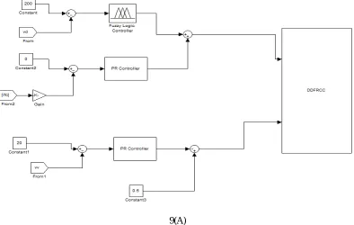
9(B)
Fig. 9 Simulation arrangement for the extension circuit control strategy (A) single fuzzy controller (B) Three fuzzy controllers.
Fig. 9 shows that to remove the double-frequency ripple current disturbance lead by the single-phase inverter load, fuzzy controllers is developed to accomplish an extra high control gain at designed resonant frequency. This will reduce both size and cost of the system.
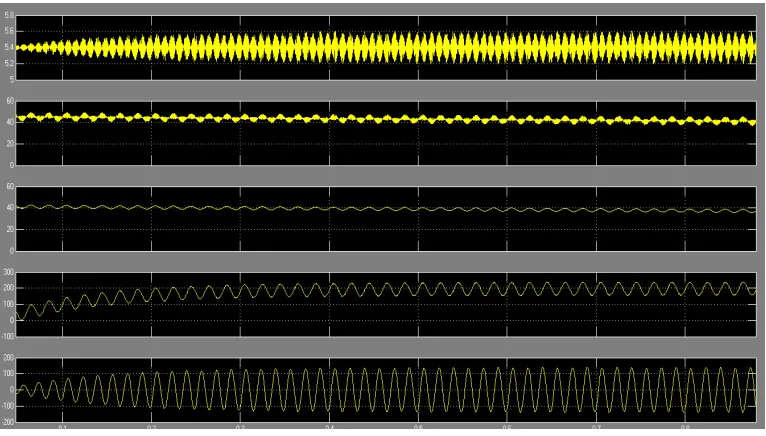
Fig. 10 Simulation results by using fuzzy control method, Cp = 220 μF, Cs = 180 μF.
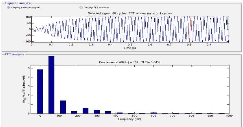
Fig. 11 shows the Ifc FFT analysis of single fuzzy controller.
From this figure, it is clear that FFT analysis using single fuzzy controller THD is reduced to 3.8%. The control system is to reduce low-frequency ripple current by using the fuzzy controller. It will reduce the control system complexity.
Fig. 12 shows the Ifc FFT analysis of three fuzzy controllers.
VI. CONCLUSION
Three-phase HFL-based fuel cell power conditioning system that can achieve low-frequency ripple-free input current by making use of direct double-frequency ripple current control. The proposed method can make full utilization of capacitive ripple energy sources. To directly eliminate the fuel cell current double-frequency ripple, PR and Fuzzy controllers are developed to achieve an extra high control gain at 120-Hz resonant frequency. This controller can stop the ripple energy propagation on inverter load to fuel cell stack, and it eliminates the disturbance from varied duty cycle. The PR and Fuzzy controllers are adopted for duty cycle control in order to achieve the d = 1 operation and remove the inverter load current and phase shift variation disturbances.
REFERENCES
[1] M. W. Ellis, M. R. Von Spakovsky, and D. J. Nelson, “Fuel cell systems: Efficient, flexible energy conversion for the 21st century,” Proc. IEEE, vol. 89, no. 12, pp. 1808–1818, Dec. 2001.
[2] M. C. Williams, J. P. Strakey, and S. C.Singhal, “US distributed generation fuel cell program,” J. Power Sources, vol. 131, no. 1/2, pp. 79–85, May 2004.
[3] B. Cook, “Introduction to fuel cells and hydrogen technology,” Eng. Sci. Educ. J., vol. 11, no. 6, pp. 205–216, Dec. 2002.
[4] S. Jung, Y. Bae, S. Choi, and H. Kim, “A low cost utility interactive inverter for residential fuel cell generation,” IEEE Trans. Power Electron., vol. 22, no. 6, pp. 2293–2298, Nov. 2007.
[5] D. De and V. Ramanarayanan, “A dc-to-three-phase-ac high-frequency link converter with compensation for nonlinear distortion,” IEEE Trans.Power Electron., vol. 57, no. 11, pp. 3669–3677, Nov. 2010.
BIOGRAPHY
N.S. PAVANI obtained graduate degree in Electrical & Electronics Engineering from JNTU-Ananthapur in the year 2012.obatined Master’s from Annamacharya Institute of Technology & Sciences – Rajampeta (Autonomous). Presently she is working as Assistant Professor in EEE department in AITS, Tirupati. Areas of interest include Power Systems.