Available online:
http://edupediapublications.org/journals/index.php/IJR/
P a g e | 525A High Torque Density Permanent Magnet BLDC Motor Using
Fuzzy Controller For Power Factor Correction
P Suman
M-tech Scholar
Department of Electrical & Electronics Engineering, Kits Engineering College, Khammam;
Khammam (Dt); Telangana, India. Email:[email protected]
M Sudhakar Assistant Professor
Department of Electrical & Electronics Engineering, Kits Engineering College, Khammam;
Khammam (Dt); Telangana, India. Email:[email protected]
Abstract-. The speed control of BLDC motor and PFC at ac mains has been achieved using a single voltage sensor. The switching losses in the VSI have been reduced by the use of fundamental frequency switching by electronically commutating the BLDC motor. This project presents a fuzzy based PFC CUK converter-fed BLDC motor drive has been proposed with improved power quality at the ac mains Moreover, the speed of the BLDC motor has been controlled by controlling the dc link voltage of the VSI. Therefore, the BLDC motor is electronically commutated such that the VSI operates in fundamental frequency switching for reduced switching losses. Moreover, the bridgeless configuration of the Cuk converter offers low conduction losses due to partial elimination of diode bridge rectifier at the front end In order to further enhancement of power factor fuzzy controlled cuk converter can be implemented. The simulation results are presented by using Matlab/simulink platform.
Index Terms—Brushless dc (BLDC) motor, continuous conduction mode (CCM), Cuk converter, discontinuous conduction mode (DCM), power factor correction (PFC), power quality (PQ).
I. INTRODUCTION
Brushless DC (BLDC) motors are recommended for many low and medium power drives applications because of their high efficiency, high flux density per unit volume, low maintenance requirement, low EMI problems, high ruggedness and a wide range of speed control. Due to these advantages, they find applications in numerous areas such as household application, transportation (hybrid vehicle), aerospace, heating, ventilation and air conditioning (HVAC), motion control and robotics, renewable energy application etc [1-2]. The BLDC motor is a three phase synchronous motor consisting of a stator having a three phase concentrated windings and a rotor having permanent magnets. It doesn’t have mechanical brushes and commutator assembly, hence wear and tear of the brushes and sparking issues as in case of conventional DC machines are eliminated in BLDC motor and thus has low EMI problems [3]. This motor is also referred as electronically commutated motor (ECM) since an electronic commutationbased on the Hall-Effect rotor position signals is used rather than a mechanical commutation.
There is a requirement of an improved power quality as per the international power quality (PQ) standard IEC 61000-3- 2which recommends a high power factor (PF) and low total harmonic distortion (THD) of AC mains current for
Class-Aapplications (<600W, <16A) which includes many household equipment’s. The conventional scheme of a BLDC motor fed by a diode bridge rectifier (DBR) and a high value of DC link capacitor draws a non-sinusoidal current, from AC mains which is rich in harmonics such that the THD of supply current is as high as 65%, which results in power factor as low as 0.8. These types of power quality indices can’t comply with the international PQ standards such as IEC 61000-3-2. Hence, single-phase power factor correction (PFC) converters are used to attain a unity power factor at AC mains. These converters have gained attention due to single stage requirement for DC link voltage control with unity power factor at AC mains. It also has low component count as compared to multistage converter and therefore offers reduced losses [4-6].
Available online:
http://edupediapublications.org/journals/index.php/IJR/
P a g e | 526selection of dc link voltage control (i.e., bucking and boosting mode). Jang and Jovanovi´c and Huber et al. have presented BL buck and boost converters, respectively. These may provide the voltage buck or voltage boost which limits the operating selection of dc link voltage control. Wei et al. have proposed a BL buck– boost converter but use three switches which will be not a cost-effective solution [12]. A fresh group of BL SEPIC and Cuk converters has been reported in theliterature but takes a large quantity of components and haslosses connected with it.
II. SYSTEM CONFIGURATION
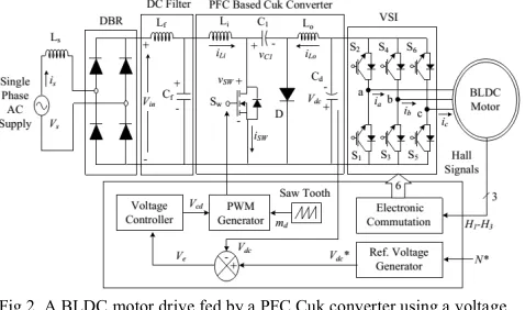
Figs.1 and .2 show the PFC Cuk converter based VSI fed BLDC motor drive using a current multiplier and a voltage follower approach respectively.
Fig. 1. BLDC motor drive fed by a PFC Cuk converter using a current multiplier approach
A high frequency metal oxide semiconductor field effect transistor (MOSFET) is used in Cuk converter for PFC and voltage controlwhereas insulated gate bipolar transistor’s (IGBT) are used in the VSI for its low frequency operation .BLDC motor is commutated electronically to operate the IGBT’s of VSI in fundamental frequency switching mode to reduce its switching losses [13-14]. The PFC Cuk converter operating in CCM using a current multiplier approach is shown in Fig.1 i.e. the current flowing in the input and output inductors (L Lo), and the voltage across the intermediate capacitor (C1) remains continuous in a switching period. Whereas, Fig.2 shows a Cuk converter fed BLDC motor drive operating in DCM using a voltage follower Approach. The current flowing in either of the input or output inductor (Li and Lo) or the voltage across the intermediate capacitor (C1) become discontinuous in a switching period for a PFC Cuk converter operating in DCM. A Cuk converter is designed to operate in all three discontinuous conduction modes and a continuous conduction mode of operation and its performance is evaluated for a wide voltage control with unity power factor at AC mains [15].
III.OPERATION OF CUK CONVERTER IN DIFFERENT MODES
The operation of Cuk converter is studied in four different modes of CCM and DCM. In CCM, the current in
inductors (Li and Lo) and voltage across intermediate capacitor C1 remain continuous in a switching period. Moreover, the DCM operation is further classified into two broad categories of discontinuous inductor current mode (DICM) and discontinuous capacitor voltage mode (DCVM). In DICM, the current flowing in inductor Lior Lo becomes discontinuous in their respective modes of operation. While in DCVM operation, the voltage appearing across the intermediate capacitor C1becomes discontinuous in a switching period. Different modes for operation of CCM and DCM are discussed as follows.
A. CCM Operation
The operation of Cuk converter in CCM is described as follows. Figs.3(a) and (b) show the operation of Cuk
Fig 2. A BLDC motor drive fed by a PFC Cuk converter using a voltage follower approach.
Converter in two different intervals of a switching period and Fig.3(c) shows the associated waveforms in a complete switching period.
Interval I: When switch Swim turned on, inductor LI stores energy while capacitor C1discharges and transfers its energy to DC link capacitor C d as shown in Fig.3(a). Input inductor current iLi increases while the voltage across the intermediate capacitor VC1 decreases as shown in Fig3(c).
Interval II: When switch Swiss turned off, then the energy stored in inductor Lo is transferred to DC link capacitor Cd, and inductor Li transfers its stored energy to the intermediate capacitor C1 as shown in Fig.3(b). The designed values of Li, Lo and C1are large enough such that a finite amount of energy is always stored in these components in a switching period.
B. DICM (Li) Operation
The operation of Cuk converter in DICM (Li) is described as follows. Figs.4(a)-(c) show the operation of Cuk converter in three different intervals of a switching period and Fig.4 (d) shows the associated waveforms in a switching period.
Available online:
http://edupediapublications.org/journals/index.php/IJR/
P a g e | 527Interval II: When switch Swiss turned off, then the energy stored in inductor Li is transferred to intermediate capacitor C1 via diode D, till it is completely discharged to enter DCM operation.
Interval III: During this interval, no energy is left in input inductor Li, hence current I Latecomers zero. Moreover, inductor cooperates in continuous conduction to transfer its energy to DC link capacitor Cd.
C. DICM (Lo) Operation
The operation of Cuk converter in DICM (Lo) is described as follows. Figs.5(a)-(c) show the operation of Cuk converter in three different intervals of a switching period and Fig.5(d) shows the associated waveforms in a switching period.
Interval I: As shown in Fig.5(a), when switch Swim turned on, inductor L stores energy while capacitor C1discharges through switch Sw to transfer its energy to the DC link capacitor Cd.
Interval II: When switch Swiss turned off, then the energy stored in inductor Li and Lo is transferred to intermediate capacitor C1and DC link capacitor Cd respectively.
Interval III: In this mode of operation, the output inductor Lo is completely discharged hence its current iLo becomes zero. An inductor Li operates in continuous conduction to transfer its energy to the intermediate capacitor C 1 via diode D.
D. DCVM (C1) Operation
The operation of Cuk converter in DCVM (C1) is described as follows. Figs.6(a)-(c) show the operation of Cuk converter in three different intervals of a switching period and Fig. 6(d) shows the associated waveforms in a switching period.
Interval I: When switch Swim turned on as shown in Fig.6 inductor L Is tares energy while capacitor C1discharges through switch Swto transfer its energy to the DC link capacitor Cd as shown in Fig.6 (d).
Interval II: The switch is in conduction state but intermediate capacitor C1is completely discharged, hence the voltage across it becomes zero. Output inductor Lo continues to supply energy to the DC link capacitor.
Interval III: As the switch Sw is turned off, input inductor LI starts charging the intermediate capacitor, while the output inductor Lo continues to operate in continuous conduction and supplies energy to the DC link capacitor.
Fig.3. Operation of Cuk converter in CCM during (a-b) different intervals of switching period and (c) the associated waveforms.
IV. DESIGN OF A PFC CUK CONVERTER
A PFC based Cuk converter fed BLDC motor drive is designed for DC link voltage control of VSI with power factor correction at the AC mains. The Cuk converter is designed for a CCM and three different DCMs. In DCM, any one of the energy storing elements Li, Lo or C1are allowed to operate in discontinuous mode whereas in CCM, all these three parameters operate in continuous conduction. The design and selection criterion of these three parameters is discussed in the following section. The input voltage Vs applied to the DBR is given as,
(1) Where Vm is the peak input voltage (i.e. √2Vs, Vs is the
rms value of supply voltage), fL is the line frequency i.e. 50 Hz. The instantaneous voltage appearing after the DBR is as,
(2) Where | | represents the modulus function. The output voltage, Vdc of Cuk converter is given as
Available online:
http://edupediapublications.org/journals/index.php/IJR/
P a g e | 528 Fig.4. Operation of Cuk converter in DICM (Li) during (a-c) differentIntervals of switching period and (d) the associated waveforms
Hence the instantaneous duty ratio, D (t) is obtained by substituting (2) in (3) and rearranging it as,
(4) The Cuk converter is designed to operate from a minimum DC voltage of 40V (Vdc min) to a maximum DC link voltage of 200V (Vdc max). The PFC converter of maximum power rating of 350W (P max) is designed for a BLDC motor of 251W (Pm) (full specifications given in Table I) and the switching frequency (fS) is taken as 20kHz. Since the speed of the BLDC motor is controlled by varying the DC link voltage of the VSI, hence the instantaneous power, Piatt any DC link voltage (Vdc) can be taken as linear function of Vdc. Hence for a minimum value of DC link voltage as 40V, the minimum power is calculated as 70W.
A. Design of Li
For Continuous or Discontinuous Current Conduction the critical value of input inductor Lice is expressed as
(5) Hence the critical value of input side inductor is directly proportional to the rams value of supply voltage; therefore the worst case design occurs for the minimum value of supply voltage (i.e. Vs=Vs min =85V). Now the critical value of input inductor at the maximum DC link voltages of 200V at the peak value of supply voltage (i.e. √2Vsmin) is calculated as,
(6) And the critical value of input inductor at the minimum value of DC link voltages of 40V at the peak value of supply voltage is calculated as
Fig.5. Operation of Cuk converter in DICM (Lo) during (a-c) different intervals of switching period and (d) the associated waveforms.
(7) Hence the value of critical input inductance is obtained lower at maximum DC link voltage. Therefore, the critical value of input inductor is selected lower than Lic200. The Performance of the Cuk converter feeding BLDC motor drive is analyzed for different values of input side inductor i.e.
Available online:
http://edupediapublications.org/journals/index.php/IJR/
P a g e | 529V.INTRODUCTIONTOFUZZYLOGIC CONTROLLER
A new language was developed to describe the fuzzy properties of reality, which are very difficult and sometime even impossible to be described using conventional methods. Fuzzy set theory has been widely used in the control area with some application to dc-to-dc converter system. A simple fuzzy logic control is built up by a group of rules based on the human knowledge of system behavior. Matlab/Simulink simulation model is built to study the dynamic behavior of dc-to-dc converter and performance of proposed controllers. Furthermore, design of fuzzy logic controller can provide desirable both small signal and large signal dynamic performance at same time, which is not possible with linear control technique. Thus, fuzzy logic controller has been potential ability to improve the robustness of dc-to-dc converters. The basic scheme of a fuzzy logic controller is shown in Fig 5 and consists of four principal components such as: a fuzzy fiction interface, which converts input data into suitable linguistic values; a knowledge base, which consists of a data base with the necessary linguistic definitions and the control rule set; a decision-making logic which, simulating a human decision process, infer the fuzzy control action from the knowledge of the control rules and linguistic variable definitions; a de-fuzzification interface which yields non fuzzy control action from an inferred fuzzy control action [10].
Fig 7 General structure of the fuzzy logic controller on closed-loop system
The fuzzy control systems are based on expert knowledge that converts the human linguistic concepts into an automatic control strategy without any complicated mathematical model [10]. Simulation is performed in buck converter to verify the proposed fuzzy logic controllers.
Fig 8 Block diagram of the Fuzzy Logic Controller (FLC) for dc-dc converters
a) Fuzzy Logic Membership Functions:
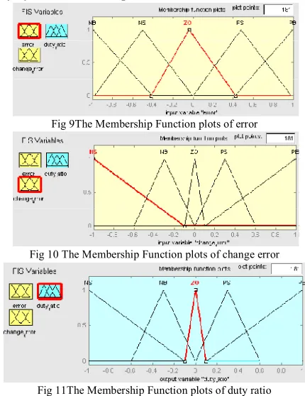
The dc-dc converter is a nonlinear function of the duty cycle because of the small signal model and its control method was applied to the control of boost converters. Fuzzy controllers do not require an exact mathematical model. Instead, they are designed based on general knowledge of the plant. Fuzzy controllers are designed to adapt to varying operating points. Fuzzy Logic Controller is designed to control the output of boost dc-dc converter using Mamdani style fuzzy inference system. Two input variables, error (e) and change of error (de) are used in this fuzzy logic system. The single output variable (u) is duty cycle of PWM output.
Fig 9The Membership Function plots of error
Fig 10 The Membership Function plots of change error
Fig 11The Membership Function plots of duty ratio
b) Fuzzy Logic Rules:
Available online:
http://edupediapublications.org/journals/index.php/IJR/
P a g e | 530Area, PS: Positive small and PB: Positive Big and its parameter [10]. These fuzzy control rules for error and change of error can be referred in the table that is shown in Table II as per below:
Table II
Table rules for error and change of error
VI.MATLAB/SIMULATION RESULTS
Fig 12 Simulation model of BLDC motor drive fed by a PFC Cuk converter using a multiplier approach
Fig 13 Simulation waveform of the BLDC motor drive with the Cuk converter operating in the CCM
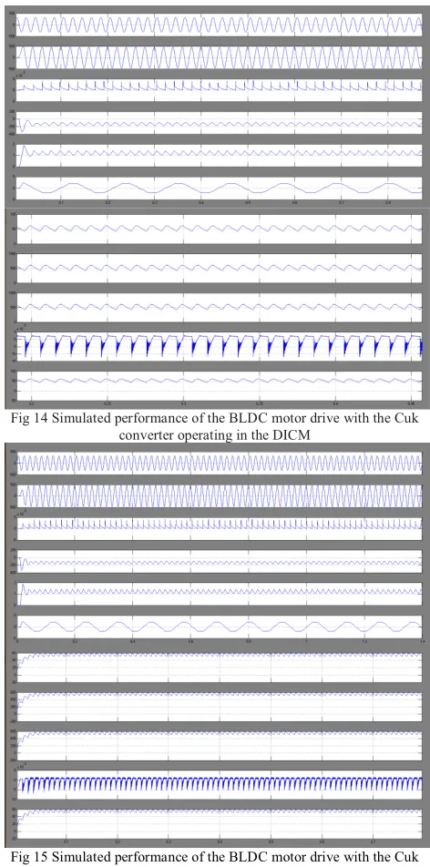
Fig 14 Simulated performance of the BLDC motor drive with the Cuk converter operating in the DICM
Available online:
http://edupediapublications.org/journals/index.php/IJR/
P a g e | 531 Fig 16 Simulated performance of the BLDC motor drive with the Cukconverter operating in the DCVM
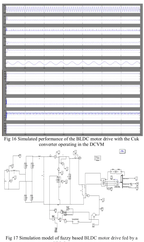
Fig 17 Simulation model of fuzzy based BLDC motor drive fed by a PFC Cuk converter
Fig 18 Simulation waveform of the BLDC motor drive with the Cukconverter operating in the CCM
V.CONCLUSION
A new speed control strategy for a BLDC using the reference speed as an equivalent voltage at dc link has been simulated .A Cuk PFC converter is employed with fuzzy controller .The speed of the BLDC has been found to be proportional to the dc link voltage; thereby a smooth speed control is observed whle controlling the dc link voltage .The PFC cuk converter has ensured near unity PF in a wide range of speed and the input ac voltage.A detailed comparison of all modes of operation has been presented on the basis of feasibility in design and the cost constraint in the development of such drive for low power applications. Finally, a best suited mode of Cuk converter with output inductor current operating in DICM has been selected for experimental verifications. The proposed drive system has shown satisfactory results in all aspects and is a recommended solution for low power BLDC motor drives.
REFERENCES
[1] J. F. Gieras and M. Wing, Permanent Magnet Motor Technology— Design and Application. New York, NY, USA: Marcel Dekker, Inc, 2002.
[2] C. L. Xia, Permanent Magnet Brushless DC Motor Drives and Controls. Beijing, China: Wiley, 2012.
[3] Y. Chen, C. Chiu, Y. Jhang, Z. Tang, and R. Liang, “A driver for the singlephase brushless DC fan motor with hybrid winding structure,” IEEE Trans. Ind. Electron., vol. 60, no. 10, pp. 4369–4375, Oct. 2013. [4] S. Nikam, V. Rallabandi, and B. Fernandes, “A high torque density permanent magnet free motor for in-wheel electric vehicle application,” IEEE Trans. Ind. Appl., vol. 48, no. 6, pp. 2287–2295, Nov./Dec. 2012. [5] X. Huang, A. Goodman, C. Gerada, Y. Fang, and Q. Lu, “A single sided matrix converter drive for a brushless DC motor in aerospace applications,” IEEE Trans. Ind. Electron., vol. 59, no. 9, pp. 3542–3552, Sep. 2012.
[6] W. Cui, Y. Gong, and M. H. Xu, “A permanent magnet brushless DC motor with bifilar winding for automotive engine cooling application,” IEEE Trans. Magn., vol. 48, no. 11, pp. 3348–3351, Nov. 2012. [7] C. C. Hwang, P. L. Li, C. T. Liu, and C. Chen, “Design and analysis of a brushless DC motor for applications in robotics,” IET Elect. Power Appl., vol. 6, no. 7, pp. 385–389, Aug. 2012.
[8] T. K. A. Brekken, H. M. Hapke, C. Stillinger, and J. Prudell, “Machines and drives comparison for low-power renewable energy and oscillating applications,” IEEE Trans. Energy Convers., vol. 25, no. 4, pp. 1162– 1170, Dec. 2010.
[9] N. Milivojevic, M. Krishnamurthy, A. Emadi, and I. Stamenkovic, “Theory and implementation of a simple digital control strategy for brushless DC generators,” IEEE Trans. Power Electron., vol. 26, no. 11, pp. 3345– 3356, Nov. 2011.
[10] T. Kenjo and S. Nagamori, Permanent Magnet Brushless DC Motors. Oxford, U.K.: Clarendon Press, 1985.
[11] J. R. Handershot and T. J. E Miller, Design of Brushless Permanent Magnet Motors. Oxford, U.K.: Clarendon Press, 2010.
[12] T. J. Sokira and W. Jaffe, Brushless DC Motors: Electronics Commutation and Controls. Blue Ridge Summit, PA, USA: Tab Books, 1989.
[13] H. A. Toliyat and S. Campbell, DSP-Based Electromechanical Motion Control. New York, NY, USA: CRC Press, 2004.
Available online:
http://edupediapublications.org/journals/index.php/IJR/
P a g e | 532VI. BIOGRAPHIES
MAROJU SUDHAKAR graduated in EEE from Kakatiya University in 2007. He received M.Tech degree in the stream of Power Electronics from Jawaharlal Nehru Technological University, Hyderabad in the year 2011. Presently working as Assistant Professor in KITS, Engineering College.