ISSN (Print) : 2320 – 3765 ISSN (Online): 2278 – 8875
I
nternational
J
ournal of
A
dvanced
R
esearch in
E
lectrical,
E
lectronics and
I
nstrumentation
E
ngineering
(An ISO 3297: 2007 Certified Organization)
Vol. 5, Issue 12, December 2016
Comparative Analysis of Nine Level Inverter
with Two Different Topologies
M.Nagaraju1, D.Ravikiran2
R&D Engineer, Dept. of Electrical, Maxwell research centre, Hyderabad, Telangana, India1
R&D Engineer, Dept. of Electrical, Maxwell research centre, Hyderabad, Telangana, India2
ABSTRACT: The multilevel inverters have been suggested for high power industrial applications. Although, there are
different topologies of multilevel inverters (MLI) like diode bridge, flying capacitor and cascaded H-Bridge multi level inverters, it is strongly recommended to use cascaded H-Bridge multilevel inverter because of its advantages compared to other topologies. In cascaded H-Bridge topology, the number of levels can be increased by increasing the number of H-Bridges which causes to increase the number of switches. The increased number levels in output voltage gives a better sinusoidal wave form with less total harmonic distortion (THD). But, the major drawback is the size and cost of the inverter increases due to more switch count. Therefore, the research has been started to reduce the switch count with more number of levels. In this paper, a nine level cascaded H-Bridge multilevel inverter with reduced switch count is proposed and analyzed. The proposed nine level multilevel inverters require less number of components to obtain same number of voltage levels when compared to diode clamped, flying capacitor and cascaded H-bridge inverter. Due to that, the switching loss and cost is reduced. Also, it generally regularizes the stair –case voltage waveform from several dc sources. The operational principle and key waveforms are analyzed and the performance of the proposed multilevel inverter is evaluated from the simulation results.
KEY WORDS: Inverter, multilevel inverters, cascaded H-bridge inverter, nine level inverter, reduced nine level
inverter.
I. INTRODUCTION
In present’s days more utilization of power converters are used for industrial application. Power Electronics is the art of converting electrical energy from one form to another in an efficient, clean, compact, and robust manner for convenient utilization [1]. It has found an important place in modern technology being core of power and energy control. It is the technology associated with efficient conversion, control and conditioning of electric power from its available input into the desired output form. Power electronics and converters utilizing them made a head start when the first device the Silicon Controlled Rectifier was proposed by Bell Labs and commercially produced by General Electric in the earlier fifties [2]. The simplest dc voltage source for a VSI may be a battery bank, which may consist of several cells in series-parallel combination. Solar photovoltaic cells can be another dc voltage source. A voltage source is called stiff, if the source voltage magnitude does not depend on load connected to it. All voltage source inverters assume stiff voltage supply at the input [3].
Multilevel Inverter (MLI) offers a number of advantages when compared to the conventional two level inverter in terms of improved d.c. link utilization and harmonic spectrum [4]. The stepped approximation of the sinusoidal output waveform with higher levels reduces the harmonic distortion of the output waveform and the stresses across the semiconductor devices and also allows higher voltage/current and power ratings. The reduced switching frequency of each individual switch of the inverter also reduces the switching losses and improves the efficiency of the inverter [6]. The different types of MLI are diode clamped, flying capacitor, cascaded MLI. Diode clamped requires more no of diodes and flying capacitor has capacitor balancing problem [7]. The cascaded H-bridge inverters having more no of advantages such as modular structure compare to other topologies such as modular structure and less no of components it is one of the topologies proposed for drive applications which meet the requirements such as high power rating with reduced THD and switching losses [8].
ISSN (Print) : 2320 – 3765 ISSN (Online): 2278 – 8875
I
nternational
J
ournal of
A
dvanced
R
esearch in
E
lectrical,
E
lectronics and
I
nstrumentation
E
ngineering
(An ISO 3297: 2007 Certified Organization)
Vol. 5, Issue 12, December 2016
topology is made with four sources and eight switches and it yields the stair case waveform with the reduced total harmonic distortion compared to conventional multilevel inverter [10-11].
II. CASCADED H BRIDGE CONVERTER
Full H-Bridge- Three level inverter
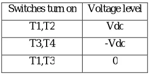
Fig.1. shows the Full H-Bridge Configuration. By using single H-Bridge we can get 2 and 3 voltage levels. The number output voltage levels of cascaded Full H-Bridge inverter are given by 2n+1 and voltage step of each level is given by Vdc/n. Where n is number of H-bridges inverter connected in cascaded. The switching table is given in Table I.
Fig. 1H-bridge inverter.
Table I shows the switching sequence for three level inverter.
Switches turn on Voltage level
T1,T2 Vdc
T3,T4 -Vdc
ISSN (Print) : 2320 – 3765 ISSN (Online): 2278 – 8875
I
nternational
J
ournal of
A
dvanced
R
esearch in
E
lectrical,
E
lectronics and
I
nstrumentation
E
ngineering
(An ISO 3297: 2007 Certified Organization)
Vol. 5, Issue 12, December 2016
III. NINE LEVEL CHB INVERTER
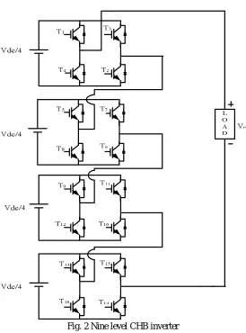
Fig. 2 Nine level CHB inverter
Figure 2 Shows the nine level multilevel inverter and Table II shows the switching states of the nine levels CHB inverter.
Here even though we have sixteen switches at any switching state only two switches are on/off at a voltage level of Vdc/4, so switching losses are reduced. In three level inverter dv/dt is Vdc, but in nine level inverter dv/dt is Vdc/4. As dv/dt reduces the stress on switches reduces and EMI reduces.
The cascaded H-bridge inverter. The cascaded means series connected to single full bridge each full bridge inverter module required Isolated DC source the value of each isolated DC source input is Vdc. Each full bridge inverter generates +Vdc, 0 and –Vdc output voltage level. The output voltage of cascaded multilevel inverter is equal to the sum of the output voltage of the each module connected in series. The output voltage level for nine level cascaded inverter are +Vdc,+3Vdc/4,2Vdc/4,+Vdc/4,0,-Vdc/4,and –2Vdc/4,-3Vdc/4,-Vdc/4 by turn on and turn off on the different switching devices. If N is the number of H-bridges or number of dc source required and n is the number of output voltage level.
The relation between N and n is given by
n=2N+1
ISSN (Print) : 2320 – 3765 ISSN (Online): 2278 – 8875
I
nternational
J
ournal of
A
dvanced
R
esearch in
E
lectrical,
E
lectronics and
I
nstrumentation
E
ngineering
(An ISO 3297: 2007 Certified Organization)
Vol. 5, Issue 12, December 2016
T1,T2,T5,T6,T9,T10,T13,T14 are on other switches are off. The switching sequence of active device for various voltage levels is given in table-II
Table II Switching table for Full H -Bridge of nine level inverter.
Switches turn ON Voltage level
T1,T2,T5,T7,T9,T11,T13,T15 Vdc/4
T1,T2,T5,T6,T9,T11,T13,T15 2Vdc/4
T1,T2,T5,T6,T9,T10,T13,T15 3Vdc/4
T1,T2,T5,T6,T9,T10,T13,T14 Vdc
T1,T3,T5,T7,T9,T11,T13,T14 0
T3,T5,T5,T7,T9,T11,T13,T14 - Vdc/4
T3,T5,T7,T8,T9,T11,T13,T14 -2Vdc/4
T3,T5,T7,T8,T11,T12,T13,T14 -3Vdc/4
T3,T5,T5,T7,T11,T12,T15,T16 -Vdc
IV.NINE LEVEL INVERTER WITH REDUCED SWITCHES
The proposed MLI configuration uses one less switch when compared to the existing 8 switches [3]. This circuit is the simplest design compared to conventional and all other existing topologies.
The design of the pulse generation circuit makes this topology differ from others so as to obtain the unique pulse pattern to turn on the switches at the proper instant. Switches T1, T2, T3, and T4 need to be compulsorily unidirectional or else the output waveform will get distorted. Reduced switches make the circuit more compact in size. Though the usage of 4 dc sources for the generation of 9-level MLI results in less utilization of sources.
Table III. Represent the switching scheme for the proposed topology.
ISSN (Print) : 2320 – 3765 ISSN (Online): 2278 – 8875
I
nternational
J
ournal of
A
dvanced
R
esearch in
E
lectrical,
E
lectronics and
I
nstrumentation
E
ngineering
(An ISO 3297: 2007 Certified Organization)
Vol. 5, Issue 12, December 2016
Table III Switching table for nine level inverter with reduced switches.
Switches turn ON Voltage level
T1,T5,T6 Vdc/4
T2,T5,T6 2Vdc/4
T3,T5,T6 3Vdc/4
T4,T5,T6 Vdc
T5,T7 0
T1,T7,T8 - Vdc/4
T2,T7,T8 -2Vdc/4
T3,T7,T8 -3Vdc/4
T4,T7,T8 -Vdc
V. MATLAB/SIMULATION RESULTS
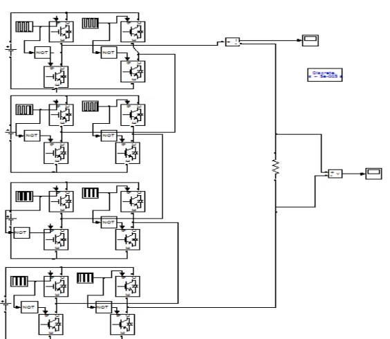
Fig. 4 Matlab/Simulation model of Cascaded H-Bridge nine level inverter.
ISSN (Print) : 2320 – 3765 ISSN (Online): 2278 – 8875
I
nternational
J
ournal of
A
dvanced
R
esearch in
E
lectrical,
E
lectronics and
I
nstrumentation
E
ngineering
(An ISO 3297: 2007 Certified Organization)
Vol. 5, Issue 12, December 2016
Fig. 6 Output Current of nine level inverter.
ISSN (Print) : 2320 – 3765 ISSN (Online): 2278 – 8875
I
nternational
J
ournal of
A
dvanced
R
esearch in
E
lectrical,
E
lectronics and
I
nstrumentation
E
ngineering
(An ISO 3297: 2007 Certified Organization)
Vol. 5, Issue 12, December 2016
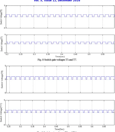
Fig. 8 Switch gate voltages T5 and T7.
ISSN (Print) : 2320 – 3765 ISSN (Online): 2278 – 8875
I
nternational
J
ournal of
A
dvanced
R
esearch in
E
lectrical,
E
lectronics and
I
nstrumentation
E
ngineering
(An ISO 3297: 2007 Certified Organization)
Vol. 5, Issue 12, December 2016
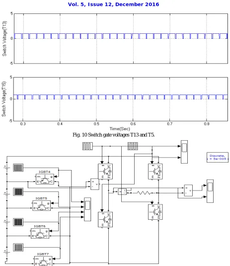
Fig. 10 Switch gate voltages T13 and T5.
ISSN (Print) : 2320 – 3765 ISSN (Online): 2278 – 8875
I
nternational
J
ournal of
A
dvanced
R
esearch in
E
lectrical,
E
lectronics and
I
nstrumentation
E
ngineering
(An ISO 3297: 2007 Certified Organization)
Vol. 5, Issue 12, December 2016
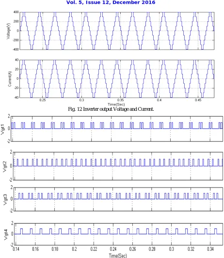
Fig. 12 Inverter output Voltage and Current.
ISSN (Print) : 2320 – 3765 ISSN (Online): 2278 – 8875
I
nternational
J
ournal of
A
dvanced
R
esearch in
E
lectrical,
E
lectronics and
I
nstrumentation
E
ngineering
(An ISO 3297: 2007 Certified Organization)
Vol. 5, Issue 12, December 2016
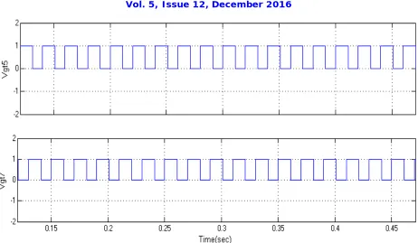
Fig. 14 Switch gate voltages (Vgt5 and Vgt7).
VI. CONCLUSION
This paper has provided a brief summary of multilevel inverter circuit topologies their analysis. Each MLI has its own mixture of advantages and disadvantages and for any one particular application, one topology will be more appropriate than the others. Multilevel inverter is used synthesize a nearby sinusoidal voltage from various levels of dc voltages and the proposed cascade H bridge inverter is used to reduce the number of switches. The proposed nine level multilevel inverters require less number of components to obtain same number of voltage levels when compared to diode clamped, flying capacitor and cascaded H-bridge inverter. Due to that, the switching loss and cost is reduced. Also, it generally regularizes the stair –case voltage waveform from several dc sources.
REFERENCES
1. J. R. Espinoza, “Inverters,” Power Electronics Handbook, M.H. Rashid, Ed. New York, NY, USA: Elsevier, 2001, pp. 225–269.
2.S. Debnath, J. Qin, B. Bahrani, M. Saeedifard, and P. Barbosa, “Operation, control, and applications of the modular multilevel converter: A review,” IEEE Trans. Power Electron., vol. 30, no. 1, pp. 37–53, Jan. 2015.
3. S. R. Pulikanti, G. Konstantinou, and V. G. Agelidis, “Hybrid seven-level cascaded active neutral-point-clamped-based multilevel converter under SHE-PWM,” IEEE Trans. Ind. Electron., vol. 60, no. 11, pp. 4794–4804, Nov. 2013.
4. Y. Hinago and H. Koizumi, “A single-phase multilevel inverter using switched series/parallel dc voltage sources,” IEEE Trans. Ind. Electron., vol. 57, no. 8, pp. 2643–2650, Aug. 2010.
5. G. Waltrich and I. Barbi, “Three-phase cascaded multilevel inverter using power cells with two inverter legs in series,” IEEE Trans. Ind. Appl., vol. 57, no. 8, pp. 2605–2612, Aug. 2010.
6. J. Ebrahimi, E. Babaei, and G. B. Gharehpetian, “A new topology of cascaded multilevel converters with reduced number of components for high-voltage applications,” IEEE Trans. Power Electron., vol. 26, no. 11, pp. 3109–3118, Nov. 2011.
7. A. K. Pandam and Y. Suresh, “Performance of cascaded multilevel inverter by employing single and three-phase transformers,” IET Power Electron., vol. 5, no. 9, pp. 1694–1705, Nov. 2012.
8. K. N. V. Prasad, G. R. Kumar, T. V. Kiran, and G. S. Narayana, “Comparison of different topologies of cascaded H-bridge multilevel inverter,” in Proc. ICCCI, Odisha, India, 2013, pp. 1–6.
9. C. M. Young, N. Y. Chu, Y. C. Hsiao, and C. Z. Li, “A single-phase multilevel inverter with battery balancing,” IEEE Trans. Ind. Electron., vol. 60, no. 5, pp. 1972–1978, May 2013.
10. J. Rodriguez, S. Bernet, P. Steimer, and I. Lizama, “A survey on natural point clamped inverters,” IEEE Trans. Ind. Electron., vol. 57, no. 7,pp. 2219–2230, Jul. 2010.
11. S. Laali, K. Abbaszadeh, and H. Lesani, “Control of asymmetric cascaded multilevel inverters based on charge balance control methods,” Int.