ISSN (Print) : 2320 – 3765
ISSN (Online): 2278 – 8875
I
nternational
J
ournal of
A
dvanced
R
esearch in
E
lectrical,
E
lectronics and
I
nstrumentation
E
ngineering
(A High Impact Factor, Monthly, Peer Reviewed Journal)
Website: www.ijareeie.com
Vol. 8, Issue 3, March 2019
Power System Stability Enhancement with
Fuzzy Type-2 based Controller
Prakash Kumar1, Kumar Prabhakar2
PG Student [Power System], Dept. of Electrical & Electronics Engineering, IES College of Technology, Bhopal,
Madhya Pradesh, India1
Assistant Professor, Dept. of Electrical & Electronics Engineering, IES College of Technology, Bhopal,
Madhya Pradesh, India2
ABSTRACT: In this paper, two different approaches are compared to design centralized Wide Area Damping Controller (WADC) to damp out the inter-area oscillations. The first designed approach is based on local Power System Stabilizer (LPSS) and second one is Interval Type-2 Fuzzy Logic sets (IT2FLS) based PSS. To design the WADC, enhance the stability and reduced the cost of the power system, geometric measure of joint controllability/observability is used to select most effective stabilizing signals and control location site in proposed model. Based on joint controllability/ observability Tie-line active power is found to be most stabilizing signals. Tie Line active power deviation conjunction with speed deviation are used as a input stabilizing signals and the designed methods are illustrated on Kundur two area four machine system. Simulation results shown that the controller designed which is based on IT2FLS performed better as compared to LPSS.
KEYWORDS: Damping controller, Fuzzy type-1, Fuzzy type-2, Inter-area oscillations, Power system stabilizer, Uncertainties.
I.INTRODUCTION
One of the problems in power systems is the low frequency oscillations arising due to different possible disturbances. These oscillations may sustain and grow to cause power system separation or collapse if no adequate damping is provided by the system controllers. In addition, with the extension of power systems, especially with their interconnection by weak tie-lines, the oscillations restrict the steady-state power transfer limits and affect operational system economics and security. A power system stabilizer (PSSs) with Lead-Lag controllers has been conventionally used to damp electromechanical oscillations in power systems with providing an auxiliary control signal to the excitation system. The design of these conventional PSSs is based on linear control theory which requires linearization of the system around a specific operating condition of the power system. Consequently, these controllers give degraded performance with varying operating conditions and sometime unable to maintain stability especially in high loading conditions [1] .
Considerable number of researches is devoted to enhance the performance of PSSs [2]. Recently, Artificial Intelligence (AI) techniques and/or optimization algorithms have been applied to PSS design and tuning problem. Application of Artificial Neural Network (ANN) for improving PSS performance is proposed in [3]-[5]. ANNs enhance PSS performance, but the main disadvantage of ANN-based techniques is the training time and the task of choosing appropriate number of neurons and layers. Another AI approach is Fuzzy Logic Control (FLC) which has been widely used in different control applications [6], [7]. The main advantage of FLC is that it does not require an accurate representation of the system and it can be tuned on the simple basis of linguistic information obtained from the knowledge of the system behavior [8].
ISSN (Print) : 2320 – 3765
ISSN (Online): 2278 – 8875
I
nternational
J
ournal of
A
dvanced
R
esearch in
E
lectrical,
E
lectronics and
I
nstrumentation
E
ngineering
(A High Impact Factor, Monthly, Peer Reviewed Journal)
Website: www.ijareeie.com
Vol. 8, Issue 3, March 2019
by small signal oscillations, has been observed in the power systems under certain system conditions, such as during the transmission of a large amount of power over long distance through relatively weak tie lines and under use of high gain exciters. These conditions introduce inter-area oscillations [0.1 Hz - 1.0 Hz] in the power system and which may cause a brownout or blackout of the whole power system.
The inter area oscillations inherent to the large inter connected grid becomes more dangerous to the system’s security and the quality of the supply during transient situation. Hence it can be said that the low frequency oscillations put limitations on operation of the power system and network’s control security. The increased interconnected network of power system carries out heavy inter change of electrical energy which invokes such poorly damped low frequency oscillation that the system stability becomes major concern.
Some examples of power system black-outs due to inter-area oscillations are as follows.[9-12]:
In early 1960's, oscillations were observed when the Detroit Edison (DE), Ontario Hydro (OH) and
Hydro-Québec (HQ) systems were inter-connected.
In 1969, oscillations were observed under several operating conditions in the Finland-Sweden (and
Norway)-Denmark interconnected system.
In 1975, unsTable oscillations of 0.6 Hz were encountered on the interconnected power system of New South
Wales and Victoria.
In 1982 and 1983, the State Energy Commission of Western Australia (SECWA) experienced lightly damped
system oscillations in the frequency range of 0.2-0.3 Hz.
On August 10, 1996, the Pacific AC Inter-tie (PACI) in WECC experienced unsTable low frequency inter-area
oscillations following the outage of four 400 kV lines.
India-2012 with a frequency range of 0.35-0.71 Hz. [13]
To damp out the inter-area oscillations, the traditional approach is Conventional Power System Stabilizer (CPSS). The basic function of PSS is to add damping to the generator rotor oscillation by controlling its excitation using auxiliary stabilizing signal. These controllers use local signals as an input signal and it may not always be able to damp out inter-area oscillations, because, the design of CPSS used local signals as input and local signal based controller do not have global observation and may does not be effectively damps out the inter-area oscillations[14].
Fuzzy controllers are mostly used for the system which are complex and mathematically ill define. It is applied almost all areas of power system problem [17]. There are two main approaches to the design of the fuzzy logic controller in the literature: First one is, Type-1 fuzzy sets, which cannot fully handle linguistics and numerical uncertainties associated with dynamic unstructured environments also Type-1 Membership Functions (MF) totally certain and second one is, Type-2 fuzzy sets which was originally presented by Zadeh in 1975, in which MFs are themselves fuzzy set. Type-2 fuzzy sets are very useful when we don’t know the exact MFs and uncertainty in the rule base of the fuzzy system. Previously it has been shown in various research work that Interval Type-2 Fuzzy Logic Controller (IT2 FLC) may achieve better control performance because of additional degree of freedom provided by Foot Print of Uncertainty (FOU) in their MFs [15]. The additional degrees of freedom make it possible to directly model uncertainties.
In this paper, a centralized Wide Area Damping controller (WADC) has been designed based on Interval Type-2 Fuzzy logic controller (IT2 FLC) by exploring the property of Type-2 Fuzzy logic Sets (T2 FLS) for Kundur Two-area four-machine system.
ISSN (Print) : 2320 – 3765
ISSN (Online): 2278 – 8875
I
nternational
J
ournal of
A
dvanced
R
esearch in
E
lectrical,
E
lectronics and
I
nstrumentation
E
ngineering
(A High Impact Factor, Monthly, Peer Reviewed Journal)
Website: www.ijareeie.com
Vol. 8, Issue 3, March 2019
II.BRIEF REVIEW ON INT2FLS
The concept of T2FLS is an extension of ordinary fuzzy sets. All the results that are used to implement an IT2FLS can be obtain using T1 FLS mathematics. The membership grades of T2 FLSs are themselves are T1 FLS. Fuzzy logic sets are said to be T2 FLS as long as any one of its antecedent or consequent or both are in Type-2 fuzzy sets.
a) Basic concept about Interval type-2 fuzzy sets:
Type-2 FS A is characterized by a Type-2 MF μ (x, u)[16]
A = (x, u),μ (x, u) ∀ x∈X,∀ u ∈ J ⊆[0,1] (1) where x, the primary variable, has domain X; u, the secondary variable, has domain J at each x∈X; J is called the
primary membership of x.
Equation (1) can also be represented by:
= ( , ) ( , )⁄ ⊆[0,1]
∈ ∈
(2)
Note that in equation (2), when all μ (x, u) = 1 then A is an Interval Type-2 Fuzzy Sets (IT2 FS).A , consists of a bounded region, this bounded region is called ‘Foot print Of Uncertainty’ (FOU) and it is union of all primary memberships, i.e.
FOU (A) = U ∈ J (3)
The IT2 FS A is also defined in terms of Upper Membership Function (UMF) and Lower Membership Function (LMF).
These two are also a T1 MFs and the region bounded by these two is called FOU as shown in Fig.2.
Fig.1 FOU (Shaded), LMF, UMF and an Embedded FS (Wavy Curve Line) for IT2 FLSs A.
From Fig.(1), The UMF is associated with the upper bound of FOU (A) and is denotedμ (x),∀ x ∈X, and the LMF is
associated with the lower bound of FOU (A) and is denoted μ (x),∀ x ∈X i.e.
μ (x)≡FOU A ∀ x ∈X (4) μ (x)≡FOU A ∀ x ∈X (5)
For continuous universe of discourse Xand U, an embedded interval T2 FS A is
A = [1⁄θ] x⁄ θ ∈
∈
J ⊆U = [0,1] (6)
Set A is embedded in A such that at each x has only one secondary variable, and there is an uncountable number of
ISSN (Print) : 2320 – 3765
ISSN (Online): 2278 – 8875
I
nternational
J
ournal of
A
dvanced
R
esearch in
E
lectrical,
E
lectronics and
I
nstrumentation
E
ngineering
(A High Impact Factor, Monthly, Peer Reviewed Journal)
Website: www.ijareeie.com
Vol. 8, Issue 3, March 2019
b) Interval Type-2 Fuzzy Logic Controller:
The design of IT2FLC based on concept of IT2 FLS. The structure of IT2 FLC as shown in figure 3. IT2 FLC and Type-1 FLC, both have same structure except ‘type-reducer’ which was introduced between interface block and defuzzifier block. The main function of type-reducer block is to reduce the type-2 fuzzy sets output of interface engine into type-1 fuzzy sets before applying it to the defuzzifier for getting the crisp input. The basic principle of operation of the IT2FLC is similar to the T1FLC. In this type of fuzzy system only enhance the degree of fuzziness of the system and all other functions like inferencing procedure, defuzzification techniques hold good for both type [18].
Fuzzifier
Inference
Rules Defuzzifier
Type-reducer
Input sets Fuzzy output sets Crisp
inputs
Crisp outputs
Type Reduced
set (Type-1)
Output Processing
Fig.2. Structure of IT2 Fuzzy Logic System
III.SIGNAL SELECTION AND CONTROL LOCATION
The nonlinear dynamic model power system is usually described by a set of differential-algebraic equation. The whole power system excluding the local PSS and wide-area damping controller can be linearized at an equilibrium point.After linearization around a given operating condition and elimination of algebricvariabes, the state space model of studied system can be written as:
ẋ = Ax + Bu
y = Cx (7)
where x∈R × , u∈R × and y∈R × are the state, inputs and output vectors respectively. A∈R × , B∈R × and
C∈R × are state, input and output matrices, respectively.
Modal analysis of linear model (7) is applied to find out the low-frequency oscillation modes and then identify the critcal inter-area mode with the help of geometric measures of modal controllability/observability.
ISSN (Print) : 2320 – 3765
ISSN (Online): 2278 – 8875
I
nternational
J
ournal of
A
dvanced
R
esearch in
E
lectrical,
E
lectronics and
I
nstrumentation
E
ngineering
(A High Impact Factor, Monthly, Peer Reviewed Journal)
Website: www.ijareeie.com
Vol. 8, Issue 3, March 2019
Geometric Approach
The geometric measure of controllability gm (k) and observability gm (k)associated with the mode kth are given
by[21]:
gm (k) = cos α(ψ , b ) = |ψb |
‖ψ ‖‖b‖ (8)
gm (k) = cos θ ϕ , c = cϕ
‖ϕ ‖ c (9)
In (8) and (9), b is the ih column of matrix B corresponding to ih input, c is the jh row of output matrix C
corresponding to jh
output. |z|and‖z‖is the modulus and Euclidean norm of z respectively. α(ψ , b ) is geometrical
angle between input vector i and kh left eigenvector and θ ϕ , c geometric angle between the output vector j and
kh right eigenvector.The joint controllability and observability index of geometric approach is defined by:
C = gm (k)∗gm (k) (10)
In the geometric approach it can prove that, higher the value of joint controllability and observability index more the stability of signal selected.In development of WADC model, each generator of proposed model has 11 state variables. Therefore, as per Kundur two area four machines model adapted in this research and the total order of the non-linear system has 44 state variables. After linearizing the non-linear test system about stable operating point of tie line active power whose initial value is 413 MW, the small signal analysis was undertaken using the PST. This resulted in one critical inter-area oscillations mode characterized by their damping ratio and frequency which are tabulated in Table-1 in bold letters.
Table-1 Dominant Oscillations Modes
Mode No. Eigen Value Damping Ratio Frequency (Hz)
05. −0.25 ± 0.65i 0.36 0.10
13. −3.59 ± 0.04i 1.00 0.01
15. . ± . -0.01 0.65
25. −8.2 ± 9.49i 0.651 1.51
27. −8.12 ± 9.68i 0.64 1.54
29. −5.66 ± 14.81 0.36 2.36
31. −4.45 ± 16.63i 0.26 2.65
The most stabilizing feedback signal selection was evaluated by geometric measure of controllability/observability approach. The candidate signals that are considered for the selection process are line active power and generator rotor speeds.
ISSN (Print) : 2320 – 3765
ISSN (Online): 2278 – 8875
I
nternational
J
ournal of
A
dvanced
R
esearch in
E
lectrical,
E
lectronics and
I
nstrumentation
E
ngineering
(A High Impact Factor, Monthly, Peer Reviewed Journal)
Website: www.ijareeie.com
Vol. 8, Issue 3, March 2019
Table-2 Geometric measure of controllability/observability approach for signal selection for mode-15 (0.05 ± 4.1i)
Signals
Generators
G-1 G-2 G-3 G-4
ω 0.0046 0.0060 0.0049 0.0065
ω 0.0031 0.0040 0.0033 0.0044
ω 0.0069 0.0091 0.0073 0.0098
ω 0.0061 0.0081 0.0065 0.0087
P3-20 0.2726 0.3588 0.2890 0.3871
P3-101 0.7042 0.9269 0.7466 1
P13-101 0.6988 0.9198 0.7409 0.9923
P13-120 0.3629 0.4777 0.3847 0.5153
IV.DESIGN OF POWER SYSTEM STABILIZER
In this study two approaches has been used for the design of PSS which is applied in multi-machine system. In this paper, Kundur two area four machine system has been taken for simulation purpose. A conventional power system stabilizer based on lead-lag compensator and the proposed IT2FLC based PSS has been implemented and their comparative results have been studied.
The basic function of PSS is to add damping to the generator rotor oscillations by controlling its excitation using auxiliary stabilizing signal(S). To provide damping, the stabilizer must produce a component of electrical torque in phase with the rotor speed deviations.
a) Lead-Lag Compensator Based PSS
The PSS used in this paper have following structure:
1 +
1 + 1 +
1 + 1 +
Where = 20, = 10, = 0.05, = 0.02, = 3 and = 5.4 for generator-2 and generator-4.
The stabilizer gain KAdetermines the amount of damping introduced by the PSS. The signal washout block is a high
pass filter, with time constant TW, which eliminates the low frequencies that are present in the controller input signal
and allows the PSS to respond only to change in input signal. The phase compensation block is usually a single first order lead-leg transfer function or cascade of two first order transfer function used to compensate the phase lag between the excitation voltage and the electrical torque of the synchronous machine. The output is the stabilization voltage to connect to the VSTAB input of the excitation system block used to control the terminal voltage of the synchronous
machine.
b) Proposed Interval Type-2 Fuzzy Logic Control based PSS (IT2FLCPSS)
In this article, the lead-lag control based CPSS is replaced by IT2FLC based PSS as shown in fig.3. For this, controller
have same input signals are taken as in case of CPSS and output of the controller is the required stabilizing signal ∆V
ISSN (Print) : 2320 – 3765
ISSN (Online): 2278 – 8875
I
nternational
J
ournal of
A
dvanced
R
esearch in
E
lectrical,
E
lectronics and
I
nstrumentation
E
ngineering
(A High Impact Factor, Monthly, Peer Reviewed Journal)
Website: www.ijareeie.com
Vol. 8, Issue 3, March 2019
Fig.3 Block Diagram representation of Interval Type-2 Fuzzy Logic Controller
To design the rule base for the fuzzy controller seven membership functions are taken for each speed deviation, tie-line active power deviation and controlled voltage. Total 49 rules bases has been designed for the optimal performance of the proposed controller which is shown in Table No.- 3 . For the design of IT2FLC, the max-min composition method is used for interface, centroid method for both type reduction and defuzzification purpose. The triangular type-2 fuzzy sets with uncertain center is used for input, output and controlled voltage.
The details of rule base that are used in this paper are as follows:
Table–3:Rule Base for Proposed IT2 FLC and Type-1 Fuzzy logic Controller
Speed Deviation
Tie- line active power deviation
NL NM NS ZE PS PM PL
PSS
NL NL NL NL NL NM NS ZE
NM NL NL NM NM NS ZE PS
NS NL NM NM NS ZE PS PM
ZE NM NM NS ZE PS PM PM
PS NM NS ZE PS PM PM PL
PM NS ZE PS PM PM PL PL
PL ZE PS PM PL PL PL PL
Where, NL-Negative large, NM-Negative medium, NS- Negative small, ZE-Zero, PS-positive small, PM-positive medium, PL-positive large.
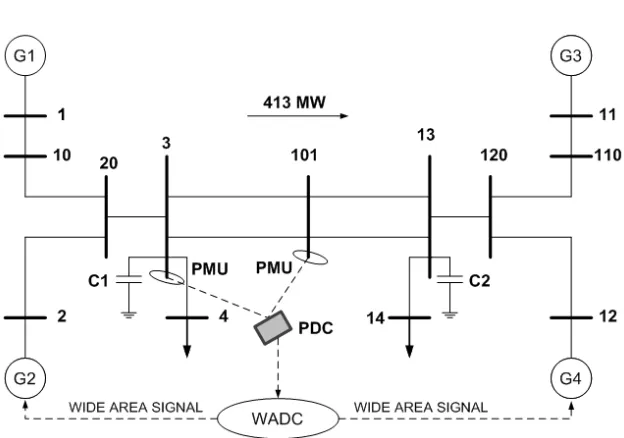
V. SIMULATION RESULTS AND COMPARISON
The test system under this research work is shown in fig. 4[22]. The system consists of two symmetrical areas linked by two parallel tie-line of length 220 Km and 230 kV. Each area is equipped with two identical round rotor generators
rated 20 kV/900 MVA. All four generators have identical parameters, except inertia coefficient (H), which are =
6.5 for Gen-1 and Gen-2 in area-1 and = 6.175 for Gen-3 and Gen-4 in area-2.
∆
∆
ISSN (Print) : 2320 – 3765
ISSN (Online): 2278 – 8875
I
nternational
J
ournal of
A
dvanced
R
esearch in
E
lectrical,
E
lectronics and
I
nstrumentation
E
ngineering
(A High Impact Factor, Monthly, Peer Reviewed Journal)
Website: www.ijareeie.com
Vol. 8, Issue 3, March 2019
Fig.4Two Area Four Machine System
Small Signal Stability Assessment
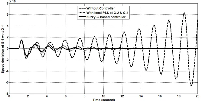
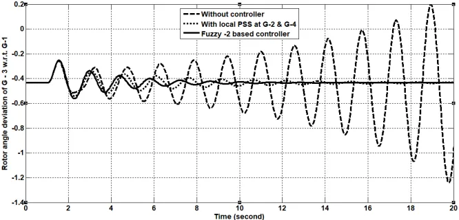
To perform the dynamic analysis of the closed loop test system for two - area four - machine systems as shown in Fig.4, a small pulse with magnitude of 5% as a disturbance was applied to the generator G-1 for 12 cycles. Then the response of tie-line active power flow from area-1 to area-2, rotor mechanical angle deviation of G1 and G3 with respect to G4 are examined by considering the test system with CPSS, andproposed fuzzy type-2 based controller. Fig. 5 – Fig. 11 responses represented different power system variables under local PSS, proposed fuzzy type-2 based controller and without controller.
ISSN (Print) : 2320 – 3765
ISSN (Online): 2278 – 8875
I
nternational
J
ournal of
A
dvanced
R
esearch in
E
lectrical,
E
lectronics and
I
nstrumentation
E
ngineering
(A High Impact Factor, Monthly, Peer Reviewed Journal)
Website: www.ijareeie.com
Vol. 8, Issue 3, March 2019
Fig. 6Change in speed deviation of G-2 w.r.t. G-1 with local PSS and fuzzy type-2 PSS
Fig. 7Change in speed deviation of G-3 w.r.t. G-1 with local PSS and fuzzy type-2 PSS
ISSN (Print) : 2320 – 3765
ISSN (Online): 2278 – 8875
I
nternational
J
ournal of
A
dvanced
R
esearch in
E
lectrical,
E
lectronics and
I
nstrumentation
E
ngineering
(A High Impact Factor, Monthly, Peer Reviewed Journal)
Website: www.ijareeie.com
Vol. 8, Issue 3, March 2019
Fig. 9Change in rotor mechanical angle of G-3 w.r.t G-4 with local PSS and fuzzy type-2 PSS
Fig. 10 Change in rotor mechanical angle of G-1 w.r.t G-3 with local PSS and fuzzy type-2 PSS
ISSN (Print) : 2320 – 3765
ISSN (Online): 2278 – 8875
I
nternational
J
ournal of
A
dvanced
R
esearch in
E
lectrical,
E
lectronics and
I
nstrumentation
E
ngineering
(A High Impact Factor, Monthly, Peer Reviewed Journal)
Website: www.ijareeie.com
Vol. 8, Issue 3, March 2019
VI.CONCLUSION
In this paper researcher designed a wide-area damping controller to damp out the inter-area oscillations in a large scale power system by using fuzzy type-2 and local PSS. The proposed controller design based on observed signal that can be obtained from the method of geometric measure of controllability and observability associated with the inter-area oscillations mode. Some simulation results are carried out to verify the effectiveness of proposed controller under small disturbance. From the simulation results, it reveals that the proposed controller damps out the inter-area oscillations effectively as compared to LPSS.
REFERENCES
[1] D.K.S.R. Prasad, “Optimal Tuning of Fuzzy Logic Power System Stabilizer Using Harmony Search Algorithm”, Int. J. Fuzzy Syst., Vol. 17, No. 3, pp. 457–470, Sep. 2015.
[2] E. Bayat, H. Delavari, "Comparison of Different Techniques For Tuning of Power System Stabilizer," Cumhuriyet Science Journal, Vol. 36, No. 3, pp. 248-257, 2015.
[3] D.K. Chaturvedi, O.P. Malik, “Generalized neuron-based PSS and adaptive PSS”, Control Eng. Prac., Vol. 13, No. 12 SPEC. ISS., pp. 1507– 1514, Dec. 2005.
[4] L.H. Hassan, M. Moghavvemi, H. A. F. Almurib, O. Steinmayer, “Current state of neural networks applications in power system monitoring and control”, Int. J. Elec. Power, Vol. 51, pp. 134–144, Oct. 2013.
[5] S. Kamalasadan, G.D. Swann and, R. Yousefian, “A Novel System- Centric Intelligent Adaptive Control Architecture for Power System 1015 Stabilizer Based on Adaptive Neural Networks”, IEEE Syst. J., Vol. 8, No. 4, pp. 1074–1085, Dec. 2014.
[6] J. Fraile-Ardanuy, P.J. Zufiria, “Design and comparison of adaptive power system stabilizers based on neural fuzzy networks and genetic algorithms”, Neurocomputing, Vol. 70, No. 16-18, pp. 2902–2912, Oct. 2007.
[7] P.S. Bhati, R. Gupta, “Robust fuzzy logic power system stabilizer based on evolution and learning”, Int. J. Elec. Power, Vol. 53, No. 1, pp. 357– 366, Dec. 2013.
[8] S.M. Abd Elazim, E.S. Ali, “Optimal Power System Stabilizers design via Cuckoo Search algorithm”, Int. J. Elec. Power, Vol. 75, pp. 99–107, Feb. 2016.
[9] Innocent Kamwa and L. Gerin-Lajoie, “State-Space System Identification-Toward MIMO Models for Modal Analysis and Optimization of Bulk Power Systems,” IEEE Trans. on Power Systems, Vol. 15, No.1, FEB. 2000.
[10] N. Martins, A. A. Barbosa, J.C.R. Ferraz, M.G. dos Santos, A.L.B. Bergamo, C.S. Yung, V.R. Oliveira, N.J.P. Macedo, “Retuning Stabilizers for the North-South Brazilian Interconnection,” IEEE PES Summer Meeting, 18-22 July 1999, Vol. 1, pp. 58-67
[11] H.Breulman, E. Grebe, M. Losing, W. Winter, R. Witzman, P. Dupuis, M. P. Houry, T. Margotin, J. Zerenyi, J. Duzik, J. Machowski, L. Martin, J. M. Rodrigues, E. Urretavizcaya, “Analysis and Damping of Inter-Area Oscillations in the UCTE/CENTREL Power System,” CIGRE 2000 in Paris, Paper 38-113.
[12] U.S.-Canada Power System Outage Tack Force: Final Report on the August 14, 2003 Blackout in the United States and Canada (on line): http://www.pserc.wisc.edu/BlackoutFinal-Web.pdf.
[13] CERC report on, ‘Grid Disturbance on 30th July 2012 and Grid Disturbance on 31st July 2012’ CERC Order in Petition No. 167/Suno-Motu/2012 dated 1st August 2012
[14] M. Aboul-Ela, A. Sallam, J. McCalley, and A. Fouad, “Damping controller design for power system oscillations using global signals,” IEEE Trans. Power Syst., vol. 11, pp. 767–773, May 1996.
[15] Kumbasar, T. ; Eksin, I. ; Guzelkaya, M. ; Yesil, E. – ‘Interval Type-2 Fuzzy Fuzzy Inverse Controller Design in Non-linear IMC Structure, Engineering Applications of Artificial Intelligence’ – IEEE Transactions, Pub: IEEE, Vol. 24, No. 6, 2012,pp. 996-1005.
[16] Mendel, Jerry M.; John, Robert I.; and Liu, Feilong; - ‘Interval Type-2 Fuzzy Logic Systems Made Simple’ – IEEE Transactions on Fuzzy Systems, Pub: IEEE, Vol. 14, No. 6, December 2006, pp. 808-821.
[17] Bansal, R.C.; - ‘Bibliography on the Fuzzy Set Theory Applications In Power Systems’ – IEEE Transactions Power System, Pub: IEEE, Vol. 18, No. 4, November 2003, pp. 1291-1299
[18] Panda, Manoj Kumar; Pillai, G.N.; and Kumar, Vijay; - ‘Power System Stabilizer Design: Interval Type-2 Fuzzy Logic Controller Approach’ – 2nd International Conference on Power, Control and Embedded Systems, Pub: IEEE, 2012.
[19] Chaudhuri B., Pal.B.C., “Robust damping of inter-area oscillations through controllable phase shifters using global signals,” IEEE PES General Meeting, Vol. 3, pp.1673-1679, 13-17 July 2003.
[20] Martins N. and Lima L. T. G., “Determination of suitable locations for power system stabilizers and Static VAR Compensators for damping electromechanical oscillations in large scale power systems,” IEEE Trans. Power Syst., vol. 5, no. 4, pp. 1455–1469, Nov. 1990.
[21] Heniche A. and Kamwa I, “Control loops selection to damp inter-area oscillations of electrical networks,” IEEE Trans. Power Syst., vol. 17, no. 2, pp. 378–384, May 2002.