Tuning the interaction Potential in
complex Plasmas
Lisa W¨
orner
Tuning the interaction Potential in
complex Plasmas
Dissertation
conducted in the framework
of a joint supervision (co-tutelle)
at the Fakult¨
at f¨
ur Physik
der Ludwig–Maximilians–Universit¨
at M¨
unchen
and the
Universit´e d’Orl´eans
handed in by
Lisa W¨
orner
born in Darmstadt.
Contents
Abstract ix
R´esum´e xi
Kurzbeschreibung xiii
Outline xv
1 Plasmas 1
1.1 States of Matter . . . 1
1.2 Temperatures . . . 2
1.3 Low temperature Plasmas . . . 2
1.3.1 General . . . 2
1.3.2 Ionization . . . 3
1.3.3 Potentials . . . 4
1.3.4 Regions . . . 5
1.4 Plasma Chemistry . . . 10
1.5 Probing Plasmas . . . 12
1.6 Summary . . . 14
1.7 R´esum´e . . . 14
1.8 Zusammenfassung . . . 15
2 Particles in Plasmas 17 2.1 Particles . . . 17
2.2 Charging . . . 19
2.3 Forces . . . 22
2.4 Particle Interactions . . . 24
2.5 Summary . . . 29
2.6 R´esum´e . . . 29
2.7 Zusammenfassung . . . 29
3 Dust Particle Formation 31 3.1 Introduction . . . 31
3.2.1 General . . . 32
3.2.2 Nucleation . . . 32
3.2.3 Coagulation . . . 34
3.2.4 Accretion . . . 34
3.2.5 Generations . . . 34
3.3 Influence on the Plasma . . . 35
3.4 Influence on the Growth . . . 36
3.5 Summary . . . 37
3.6 R´esum´e . . . 37
3.7 Zusammenfassung . . . 38
4 Particle Formation in a DC Discharge 39 4.1 Previous Experiments . . . 39
4.2 Experimental Setup . . . 40
4.3 Results . . . 41
4.3.1 Observation . . . 41
4.3.2 Particle Transport . . . 42
4.3.3 Absence of Growth . . . 45
4.3.4 Scanning Electron Microscope Results . . . 46
4.3.5 Transportation Time . . . 47
4.3.6 Plasma Instabilities . . . 48
4.4 Possible further Experiments . . . 49
4.5 Summary . . . 50
4.6 R´esum´e . . . 51
4.7 Zusammenfassung . . . 51
5 Decharging 53 5.1 Previous Experiments . . . 53
5.2 Experimental Setup . . . 54
5.3 Experimental Procedure . . . 55
5.4 Analysis . . . 55
5.5 Results . . . 59
5.6 Possible further Experiments . . . 61
5.7 Summary . . . 62
5.8 R´esum´e . . . 62
5.9 Zusammenfassung . . . 62
6 Confined Particle Clusters 63 7 Cluster Rotation 69 7.1 Experimental Setup . . . 69
7.2 Observation . . . 70
CONTENTS vii
7.4 Results . . . 73
7.4.1 Frequency Dependence . . . 73
7.4.2 Driving Mechanisms . . . 74
7.4.3 Height Dependence . . . 76
7.4.4 Vertical Resonance Frequency . . . 76
7.4.5 Suspending a Single Particle . . . 77
7.5 Possible further Experiments . . . 78
7.6 Summary . . . 78
7.7 R´esum´e . . . 78
7.8 Zusammenfassung . . . 78
8 Competing Cluster Symmetries 81 8.1 Experimental Setup . . . 81
8.2 Parameters . . . 83
8.3 Rotation . . . 84
8.4 String Analysis . . . 87
8.4.1 Spatial Correlation . . . 87
8.4.2 Temporal Correlations . . . 88
8.5 Description of Strings . . . 90
8.5.1 String Identification . . . 90
8.5.2 String Lifetimes . . . 93
8.5.3 Individual String Geometry . . . 93
8.6 Global Cluster Symmetry . . . 99
8.7 Possible further Experiments . . . 100
8.8 Summary . . . 100
8.9 R´esum´e . . . 101
8.10 Zusammenfassung . . . 101
Summary 103 R´esum´e 105 Zusammenfassung 107 A Synchronization 109 A.1 Motivation . . . 109
A.2 Without Function Generators . . . 109
A.3 With Function Generators . . . 110
A.4 Pictures . . . 110
A.5 Calculations . . . 112
A.5.1 General . . . 112
A.5.2 Without function Generators . . . 113
List of Figures 118
Bibliography 130
Abstract
Plasmas are next to the solid, liquid and gaseous phase the fourth state of matter. It is established by ionizing a gas. About 99% of the visible matter in the universe is in the state of plasma. The industrial, medical and scientific benefits of plasmas led to a variety of artificially produced plasmas. In plasmas dust particles can grow. Especially in industrial plasmas particle formation in the plasma gas phase is very common. The fundamental understanding of the growth is of vital importance in order to suppress undesired particle formation or to deposit particles and films in a certain region.
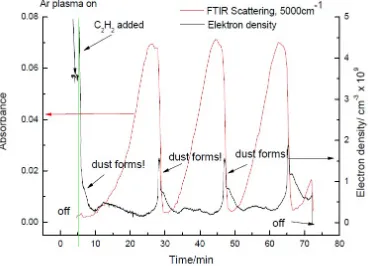
In terms of this thesis the particle growth in a direct current (DC) discharge by using acetylene will be discussed. It has been observed that the particle growth depends on the neutral gas flow fed into the plasma chamber. Depending on the applied flow different growth frequencies and transport phenomena are shown. The observations recorded by a spectrometer will then be complimented by pictures from the particles taken by a scanning electron microscope.
Introducing artificial particles into a plasma rather than growing them there yields several advantages. The particle sizes can be controlled, including the possibility of particle mixtures. Furthermore, particles with bigger diameter can be introduced than what can be grown on reasonable time scales in a plasma.
Several possible experiments with injected particles underline the interdisciplinary char-acter of the plasma environment. To understand the inter particle interactions the particle charge is a crucial parameter.
In this thesis several experiments determining the particle charge will be discussed. In this frame the experiments on board of the International Space Station have been performed to measure the residual charge in the particle afterglow.
R´
esum´
e
A cot´e des solides, des liquides et des gaz, le plasma est le quatri`eme ´etat de la mati`ere. Il est g´en´er´e en ionisant un gaz. Dans l’univers, 99% de la mati`ere est l’´etat de plasma. L’´emergence de plusieurs types de plasmas artificiels est due aux multiples et diff´erentes applications, tr`es int´eressantes les unes que les autres, des plasmas dans des secteurs aussi vari´es que l’industrie, l’´energie, le biom´edical et la science. Tr`es souvent, des particules solides peuvent se former dans les plasmas. Ceci a tout particuli`erement ´et´e observ´e dans ceux utilis´es dans l’industrie. La compr´ehension des m´ecanismes de leur nucl´eation et croissance est d’une importance capitale en vue de trouver des solutions pour inhiber leur formation ou d’´eviter qu’elles ne se d´eposent sur les surfaces en cours de traitement.
L’objectif du travail de recherche entrant dans le cadre de cette th`ese est l’´etude de la formation de particules dans un plasma g´en´er´e par d´echarge ´electrique continue. Il a ´
et´e observ´e que ce ph´enom`ene d´epend du flux de gaz neutre inject´e dans l’enceinte du r´eacteur. J’ai mis en ´evidence que la fr´equence de formation est li´ee `a ce param`etre. Les observations enregistr´ees `a l’aide d’un spectroscope sont compl´et´ees et corr´el´ees aux photographies obtenues par microscopie ´electronique `a balayage.
L’injection de particules dans le plasma plutˆot que de proc´eder `a les faire croitre pr´esente certains avantages. On peut contrˆoler leur taille y compris de la cas de m´elanges de particules. On tout particuli`erement injecter des particules ayant des tailles beaucoup plus importantes que celles que l’on forme sur des gammes de dur´ees raisonnables des plasmas utilis´es.
Plusieurs exp´eriences r´ealis´ees avec des particules inject´ees ont mis en exergue le car-act`ere pluridisciplinaire du milieu plasma. Afin de comprendre les interactions mutuelles entre particules il est crucial de d´eterminer la charge port´ee par les particules.
Plusieurs exp´eriences r´ealis´ees au cours de cette th`ese et pr´esent´ees ici ont port´e sur la d´etermination de ce param`etre fondamental. Dans ce cadre une s´erie d’exp´erience a ´et´e r´ealis´ee `a bore de la Station Spatiale Internationale (ISS) dans le but de d´eterminer la charge r´esiduelle des particules dans la phase de post-d´echarge.
Kurzbeschreibung
Neben fester, fl¨ussiger und gasf¨ormiger Phase sind Plasmen der vierte Aggregatzustand der Materie. Ionisierte Gase machen etwa 99% der sichtbaren Materie im Universum aus. Neben den nat¨urlich vorkommenden Plasmen f¨uhrte der industrielle, wissenschaftliche und medizinische Nutzen zu einer Vielzahl von k¨unstlich erzeugten Plasmen. Teilchenwachstum ist ein h¨aufiges Ph¨anom¨an in Plasmen. Besonders in der Gasphase industrieller Plasmen ist es weit verbreitet. Das grundlegende Verst¨andnis des Wachstums ist von unmittelbarer Be-deutung f¨ur die Vermeidung der Bildung unerw¨unschter Partikel sowie f¨ur die Deponierung von Teilchen und Filmen in erw¨unschten Bereichen.
Im Zuge dieser Arbeit wird das Wachstum von Partikeln in einer Gleichstrom (DC) Ent-ladung unter Verwendung von Acetylen beschrieben. Die Abh¨angigkeit des Wachstums von dem Neutralgasfluß, die erreichten Teilchengr¨ossen und die, aus dem repetetiven Charak-ter des Wachstumsprozesses resultierende, Wachstumsfrequenz werden gezeigt. Des Weit-eren werden Ver¨anderungen des Plasmas und der Teilchentransport entlang der Kammer beschrieben. Die von einem Spektrometer aufgenommenen Daten werden durch Rasterelek-tronenmikroskopbilder der Teilchen erg¨anzt.
Neben der Teilchenformation k¨onnen Teilchen injiziert werden. So kann die Teilchen-gr¨osse von vorneherein festgelegt werden und auch Mischungen aus Teilchen verschiedener Gr¨ossen sind m¨oglich. Zus¨atzlich k¨onnen Experimente mit Teilchen gr¨osseren Durchmessers durchgef¨uhrt werden.
Die zahlreichen m¨oglichen Experimente mit injizierten Teilchen betonen den interdiszi-plin¨aren Charakter komplexer Plasmen. Die Ladung der Teilchen dominiert ihre Wechsel-wirkung und ist daher ein entscheidender Faktor.
In dieser Arbeit werden verschiedene Experimente zur Bestimmung der Teilchenladung vorgestellt. In diesem Zusammenhang wurden Experimente an Bord der Internationalen Raumstation durchgef¨uhrt. Die Restladung der Teilchen nach Erl¨oschen des Plasmas wird bestimmt. Verschiedene Situation mit und ohne zus¨atzlichem elektrischen Feld wurden untersucht. Ohne zus¨atzliches Feld verteilen sich die Ladungen um null, mit Feld zeigt sich ein Trend zu positiver Teilchenladung.
Outline
The main objective of this thesis is the tuning of the particle interaction potential in complex / dusty plasmas.
To understand the particle behavior, first an introduction on the basic plasma princi-ples, chapter 1, will be given. Afterwards the behavior of particles levitated in a plasma will be discussed, chapter 2. This includes charging and particle interactions.
This is followed by a description of particle formation in plasmas in general, chapter 3. The results of the experiments on particle formation in a DC discharge are then discussed in chapter 4.
Since the particle charge is one of the most fundamental parameters in complex/dusty plasmas a way to determine the charge in the plasma afterglow will be described in chap-ter 5.
In chapter 6 earlier experiments on the tuning of the interaction potential are discussed. The final two chapters 7 and 8 are then dedicated to experiments on the interaction potential. Furthermore, interesting side effects will be discussed.
I have to refer to my own publications throughout the description of my experiments. My publications are designated different numbers to distinguish them easily from the rest of the references.
• [MY1]: Effect of Rotating Electric Field on 3D Complex (Dusty) Plasma
• [MY2]: The Formation and Transport Phenomena of nanometer-sized Particles in a DC Plasma
Chapter 1
Plasmas
1.1
States of Matter
Molecules and atoms tend to organize themselves according to their properties and the surrounding conditions, e.g. pressure, temperature, and volume. The three basic states in which matter occurs are solid, liquid and gas.
Phase transitions can be displayed using a phase diagram. Phase diagrams describe the state of a given material depending on two thermodynamical parameters, e.g. pressure and temperature [136]. Transitions from one to another state occur along certain lines in these diagrams. In case of a phase transition the temperature and the pressure will stay constant until the system has been changed completely. The only difference is the critical point beyond which the system passes into a supercritical fluid where gaseous and liquid phase are no longer distinguished. This has for instance been reported by C. Eckertet al., [59].
Ionizing a gas leads to a fourth state: the plasma. Even in an only weakly ionized gas the charged species dominate the behavior of the system. In difference to the other three states the border between a system being a plasma or a gas is not sharp since the gas will undergo a slow transition while being (partly) ionized.
Plasmas differ from gases in some major respects. Since the gas molecules are ionized more than one active species occur in the plasma. Collisions and external forces lead to a non-Maxwellian ion and electron velocity distribution inside the plasma. Collective phenomena in response to electromagnetic fields are characteristic for plasmas.
Plasmas are a very common state of matter. Actually about 99% of the visible1 matter
in the universe is in the state of plasma. Plasmas occur in astrophysical environments as well as on earth. In addition artificial plasmas are employed for instance in industrial, medical, and scientific applications.
Typical astrophysical plasmas are stars [56, 172], comet tails, supernova explosions [14], planetary spokes [74, 157], and interstellar nebulae [81]. Dust has been found responsible
1In this thesis the visible range means any wavelength in the regime visible to the human eye, i.e.
for comet and planetesimal formation in nebulae [215]. The simulations by Supulver et al.
[202] demonstrate the condensation of sub micrometer sized particles from present gas and their coagulation in nebulae, forming planetesimal. In their paper the necessity of charged species during this process is emphasized. In earths environment flames, polar auroras, and lightning [175] are naturally occurring plasmas. Artificially produced plasmas include fluorescent lights, industrial processing [19], spacecraft propulsion [126], plasma torches, particle sources [11] particle beam collisions [84], and acceleration [23]. In addition to the industrial and every day life applications, plasmas have shown to be useful in health care [193]. This includes sterilization, skin treatment, wound healing, cancer treatment and dental care.
1.2
Temperatures
In systems being in thermal equilibrium the temperature describes the particles kinetic energy. Even though many plasmas are not in thermal equilibrium, and therefore the velocity distributions are far from being Maxwellian, a temperature for electrons and ions can be approximated. Depending on the relation between the temperatures of the electrons, ions and the remaining neutral gas atoms2 plasmas can be classified.
If electron and ion temperatures do not differ much the plasma is called thermal. The opposite situation is called a non-thermal plasma. There the ion temperature is almost at the level of the neutral temperature whereas the electron temperature is much higher. In most cases the ion temperature in non-thermal plasmas is therefore the same as the surrounding room temperature.
The degree of ionization is linked to the ion and electron temperature as well as to the electron density. If the electron kinetic energy is too low the ions and electrons recombine and the plasma turns into gas.
1.3
Low temperature Plasmas
1.3.1
General
It is possible to produce thermodynamically open low temperature plasmas. In this case the ions are almost in thermal equilibrium with the neutral gas atoms and thus leading to a situation in which the plasma is operated at room temperature. However, the electron kinetic energy is much higher than the ion kinetic energy.
Collisions of ions with neutrals are dominating the ion-ion and ion-electron collisions leading to a temperature of the plasma of the order of that of the neutral gas. To achieve an environment like this a gas at up to atmospheric pressures is exposed to electric powers
2As it has been previously stated plasmas are (partly) ionized gases and include still some neutral gas
1.3 Low temperature Plasmas 3
of several Watts. The simplest way to ionize a gas is to apply a direct current. This type of discharge is hence also called DC discharge or DC plasma. If the applied voltage is alter-nated with a frequency in the order of several MHz it is called RF (radio frequency driven) plasma. Due to availability of industrial and therefore cheaper generators, RF plasmas are usually ignited at frequencies of 13.56 MHz and 81.6 MHz. There are different types of RF plasmas depending on the way of ionization. In capacitively coupled discharges the plasma is ignited in between two electrodes. If both electrodes are powered the discharge can be operated in push-push or push-pull mode depending on the phase shift of the applied voltages. Different from this works the inductively coupled discharge. This discharge is ignited using a coil and the induction of magnetic and electric fields.
In most of the laboratory environments plasmas are based on noble gases as Neon, Kryp-ton, and Argon. In addition reactive gases, such as Acetylene or Methane can be injected into the plasma changing its properties. Some applications have shown that electronega-tive plasmas have advantages with respect to the ones based on noble gases. Especially for sputtering and etching plasmas based on Oxygen are of advantage [42].
1.3.2
Ionization
By delivering energy to a gas its molecules can be excited. The excitation of a given molecule is determined by the electron energy levels. The levels are defined by the inhabited orbitals. An orbital describes the probability of electron appearance in the vicinity of the atoms nuclei. They are characterized by quantum numbers corresponding to the electrons energy and angular momentum. According to the angular momentum the orbitals are named s, p, d, and f orbital. They differ in shape and population [179].
An excited atom will regain its ground state by releasing energy in form of photonic emission. Since the energy levels are discrete a certain atom or molecule will emit photons of discrete energy and thereby wavelength. This can be used to determine the compounds of a given material as well as for calibrating optical tools. In case of argon the most important transitions lead to emissions at 751 nm and 811 nm [152].
If the energy delivered to a molecule is high enough electrons can be removed completely. In addition positive ions and neutrals can pick up electrons. However, in most cases the volume recombination is negligible compared to the loss of charged species on the confining walls. Thus ionization and recombination are present at all times and the plasma is only sustained by constantly applying an electric field of sufficient intensity.
The degree of ionizationαis described by the number density of neutral gas atoms (nn)
and ions (ni). The formula is given as:
α= ni
ni+nn
(1.1)
If α1 the plasma is considered to be weakly ionized [68, 190]. Throughout the experi-ments described in this thesis the ionization degreeα ≈10−5−10−7.
density of free electrons neequal to the number density of ions times the average ionization.
Using the Boltzmann equation and the plasma potential the number densities can also be written as [68, 159]:
ne =ne0·exp(−
eΦ
kBTe
)
ni =ni0·exp(−
eΦ
kBTi
)
(1.2)
In this equation ne0,i0 are the initial electron and ion densities. Due to thermal losses
these are reduced depending on the plasma potential, and the electron respectively ion temperatures Te,i.
1.3.3
Potentials
Plasmas being determined by electro-magnetic fields are best described by the Maxwell equations [200].
~
∇ ·E~ = ρ
0
~
∇ ·B~ = 0
~
∇ ×E~ =−∂ ~B
∂t ~
∇ ×E~ =µ0~j+µ00
∂ ~E ∂t
(1.3)
In these equations ρand~j are the charge and current densities.
In plasmas the time variation of the magnetic field can usually be neglected [66]. Hence the electric field can be derived from a scalar potential Φ
E =−∇Φ (1.4)
leading to the Poisson equation.
∆Φ = ρ
0
(1.5)
The solution to this equation is in linear approximation the so-called Debye-H¨uckel (Yukawa) potential [159].
Φ(r) = q 4π0r
exp(− r
λD
) (1.6)
With
λD = (λ−De2 +λ
−2
Di)
−12 (1.7)
being the total Debye length. The individual Debye lengths for ions and electrons respec-tively are given by
λDi,e=
s
0kBTi,e
ni,ee2
1.3 Low temperature Plasmas 5
The total Debye length describes the distance in which the measured charge of a particle is declined to 1e of the original value [159]. Hence it is a measure of the screening of a particle. Therefore the Debye length is also called Debye screening length or screening length. The screening length is the typical length along which particles see the strong electric field of another particle. Since plasmas are quasi-neutral the individual particle charge is of high importance. The interaction is described by the plasma condition [68]
Ne =
4π
3 λ
3
Dne 1, (1.9)
giving the total number of electrons inside the Debye radius around a certain particle. In addition collective phenomena can be observed. A typical phenomenon are charge density oscillations traveling at a characteristic frequency, the so-called plasma frequency
ωp i,e =
s
e2n
i,e
0mi,e
. (1.10)
If any field with a frequency above the ion (electron) plasma frequency is applied, the ions (electrons) can not follow the excitation any more. As the plasma frequency is proportional to the square root of the inverse particle mass, the ion plasma frequency is much lower than the electron plasma frequency. Since this thesis has been dedicated on the manipulation of the ions in the plasma the plasma frequency will be of high importance.
1.3.4
Regions
General
Containing equal numbers of positively and negatively charged particles parts of plasmas are quasi-neutral. The volume in which the quasi-neutrality is preserved is called bulk plasma [128]. The combination of quasi-neutrality and free charge carriers leads to a situation of almost infinite electric conductivity of the bulk plasma.
However, every laboratory plasma interacts with the surrounding confinement. Close to the walls a positive space charge builds up introducing a potential barrier confining the electrons inside the plasma. This results in strong electric fields. The volume in which these fields are present and the quasi-neutrality is violated is called sheath [128]. In the sheath basically no electrons are present. Thus electron impact ionization, dissociation, and excitation take place only in the bulk plasma. The bulk can thus be distinguished from the sheath due to the increased glow level.
The electrons are responsible for impact dissociation and ionization. These two pro-cesses lead to the increased plasma glow in the vicinity of higher electron density. Electrons are mainly present in the bulk, see e.g. figure 1.3. Thus, the sheath edge can be distin-guished from the bulk plasma by the increased luminosity.
higher than the Bohm velocity
v ≥uB =
r
kBTe
mi
. (1.11)
To fulfill Bohms criteria the electric field of the sheath has to penetrate into the bulk plasma forming a pre-sheath.
Due to the electric field in the sheath the ion stream velocity is very high. Thus, their contribution to the absolute screening is reduced. The Debye length in the sheath is therefore dominated by the electron Debye length. In the bulk the opposite behavior appears. The electron temperature in the bulk is much higher than the one of the ions. Hence the electron contribution to the Debye length can be neglected and the screening is determined by ions [128, 174].
DC Discharges
In direct current (DC) plasmas the axial plasma is not uniform. If a DC plasma is produced inside a long cylinder eight regions occur along the tube: anode dark space, anode glow, positive column, Faraday dark space, negative glow, Crookes dark space, cathode glow, and Aston dark space. The regions are shown in a sketch in figure 1.1 as reproduced from [128].
The strongest voltage drop occurs along the Crookes dark space3. In this dark space even the high energetic electrons are repelled and can not reach the cathode. The discharge is maintained by the production of secondary electrons by ions emerging from the cathode. Due to the current induced by the ionization the electron density and flux grow along the dark space. This exponential growth leads to the initial breakdown starting the discharge. The occurring hysteresis shown in figure 1.2 are due to the initial breakdown conditions of the discharge.
The increasing density of fast electrons leads to a bright region close to the cathode, the
negative glow. In this region ionization and excitation of the gas is enhanced. In order to fulfill the conditions as present in the following positive column the fast electrons have to be dissipated and the electric field has to drop. Thus the electrons first loose their energy due to collisions and are then re-accelerated in the weak field. The acceleration length is approximately their mean free path. The resulting dark region is called Faraday dark space.
The conditions in the positive column are quite similar to the conditions in the ones in the bulk plasma. The electric field balances the energy loss due to ionization and excitation. The axial uniform plasma is sustained by a weak electric field.
Since the electron drift velocity in the weak electric field of the positive column is smaller than the thermal electron velocity an electric field is needed to prevent the thermal electrons from hitting the anode. This region is called anode fall. It has a double layer structure since the anode has to be positive with respect to the positive column in order to sustain the current.
1.3 Low temperature Plasmas 7
Figure 1.1: The different regions (a) in a DC glow discharge and the distribution of the fields and space charges(b), [128].
The remaining regions do not determine the behavior of the discharge and will not be discussed here. Any interested reader might read the according sections in Refs. [128, 174] from which also the information on the described regions has been taken.
In addition the characteristics of the discharge as a whole depend on the applied current. The established voltage depends on the pressure. A typical distribution for a pressure of 1 Torr (≈133 Pa) is shown in figure 1.2. At low currents the glow discharge slowly builds up. Beneath IA the discharge is called Townsend or dark discharge. At intermediate
currents (IA < I < IB), where the slope of the distribution is negative, the normal glow
establishes. This is the region in which most of the low temperature experiments are performed. It is followed by the abnormal glow (IB < I < IC) before the voltage drops
suddenly and the plasma is called arc discharge.
Figure 1.2: The graph demonstrates the U-I characteristics of a DC discharge, [128].
regions of the striations are sharply divided. The typical triangle or round shape of the striations is caused by a focusing effect. That the striations reach out to the walls is due to radial electron diffusion. The electrons far from the center experience weaker fields and need longer distances before having reached the energy necessary for excitation. Thus, the distances between the striations off-center are wider. Often moving or instable striations are observed, leading to a smearing of the glow.
RF Discharges
A plasma can also be induced by applying an alternating current to a gas-filled volume. The usual alternation frequencies are 13.56 and 81.6 MHz. Hence these plasmas are called radio frequency driven plasmas or RF plasmas. If the current is applied to one or two planar electrodes the discharge is calledcapacitively coupled. The choice of exact excitation frequencies is due to availability of industrial generators. In principle any RF current can be employed to induce a plasma with similar properties.
To excite and ionize gas atoms or molecules energy has to be delivered to them. In case of capacitively coupled RF discharges this is mainly due to two processes: ohmic
and stochastic heating [128]. In a rather simple model in the bulk plasma the energy is transfered by electron-neutral collisions. This is called ohmic heating. In contrast to this the momentum transfer in the sheath is mainly due to the alternating high electric field. The process is therefore called stochastic heating [162].
1.3 Low temperature Plasmas 9
Figure 1.3: Sketch of a radio frequency driven plasma(a). Plot (b) displays the distribution of the electron and ion density along the plasma and the sheath, [128]. Next to it a more realistic distribution of the electron and ion densities in the sheath is given. This figure is reproduced from [127]. Furthermore, the development of the applied RF voltage Vp, the resulting plasma potentialVp, the corresponding time averageVp, and the self biasVdc is shown,[71].
A sketch of the situation in a RF discharge is shown in figure 1.3(a). The sheath that forms next to the powered electrode (left hand side) is usually bigger than the one that forms next to the grounded plate (right hand side). In between the two sheaths the quasi-neutral bulk plasma forms. Since the electron mobility is high enough to follow the electric fields the electrons will stay in the central region of the plasma whereas the slower ions penetrate into the sheath region. An ideal representation of this is shown in figure 1.3(b), [128]. A more realistic picture of the ion and electron density as well as the space averaged electron density in the sheath is shown in figure 1.3(c), [127]. Several simulations of the electrons passing through the volume between two electrodes including their density, temperature, and impact on the carrier gas have been conducted, [71, 212].
The strong potential difference between the electrode and the plasma results in a bias voltage which can be measured on the electrode. The bias voltage depends on the plasma parameters. Thus, further information on the plasma state and change can be gained by measuring it over time [125]. The development of the RF voltage Vrf and the plasma
potential Vp are displayed in figure 1.3(d), [71]. Furthermore, it shows the time averaged
plasma potential Vp and the constant self bias Vdc.
Figure 1.4: Sketch of the electrical network of a radio frequency driven plasma with the matching network (a), [214]. Panel (b) shows a more general electrical description of the plasma itself. In this the sheaths are equal to an array of a capacitor and a resistor whereas the bulk is represented by a resistor alone, [71].
currents. A scheme of the matching network as attached between a RF generator and a discharge chamber is displayed in figure 1.4(a), [214].
Electrically the plasma can be described as the neutral bulk plasma of almost infinite conductivity and two capacitors representing the sheaths. This is represented by the sketch in figure 1.4(a). Even if the electric plasma description displayed there might be correct for this special case, the description of the plasma (sheath and bulk) given in (b) is more general and accurate. The figures are reproduced from [214](a) and [71](b).
Another way of igniting a plasma is by using a coil wrapped around a gas filled volume. If a RF current is applied to the coil a magnetic field is induced. The magnetic field is then responsible for the ionization and acceleration of ions. Since this method induces electromagnetic fields a chamber operated in this way is called inductively coupled.
1.4
Plasma Chemistry
Depending on the neutral gas mixture and the plasma parameters a lot of different chemical reactions occur in plasmas. Some of these processes are endothermic, others exothermic. The energy delivered by the plasma enables all of these processes. Thus depending on the applied power the probability of a process and thereby the concentration of certain species can be influenced. It is important to note that some reactions are reversible while others cannot be undone. This is of special significance if a desired species shall be produced.
Two reactions have to be distinguished: those in the gas phase and those including the surfaces. In both cases dissociation, ionization, and attachment lead to new molecules. This is especially true if the plasma is not run by using a pure noble gas but in air or in a composition including portions of other gases such as acetylene or methane. Etching rate, occurring anisotropies, and composition depend on the concentration and energy distribution amongst the species in the plasma.
1.4 Plasma Chemistry 11
and dissociation:
e−+AB→AB++ 2e− ion-electron pair production (1.12)
e−+AB→A+B++ 2e− dissociative ionization (1.13)
e−+AB→A∗+B∗+e− radical production (1.14)
e−+AB →A−+B negative ion production (1.15) Due to vibrational and rotational modes auto dissociation
AB+→A+B+ or A++B, (1.16) auto ionization
AB→AB++e− and (1.17) auto detachment after endothermic negative ion production
A−→A+e− (1.18)
can occur. In case the ion production is exothermic the electron is not probable to detach from the ion again. Electrons can also be removed from negative ions by dissociation. The collision with another electron or any other particle can lead to detaching the electron from the negative ion leaving a neutral atom or a radical.
In addition, to the processes involving electrons chemical reactions in the gas phase are common:
A+B *) C+D (1.19)
These do not necessarily take place until the total amount of initial molecules (here: A and B) is transformed. According to the chemical energies necessary to produce either combination a chemical equilibrium will be reached in which usually all four components are present in the plasma.
Reactions including atoms from the surrounding surfaces are exclusively exothermic. Only if energy is delivered to the surface atoms can be released (etching / sputtering). The reversed reaction (deposition) may be endothermic, too.
A(gas) +S(surf ace)*) A:S(gas). (1.20) Several consecutive reactions might be necessary for some of the very general reactions introduced above. In some cases even catalysts may be necessary. Similarly the presence of certain molecules or atoms may inhibit otherwise common reactions.
1.5
Probing Plasmas
Gaining informations on what is going on in a plasma is very important with respect to controlling and reproducing certain conditions. In this section several probing methods will be introduced and discussed. The most preferable ones are the non-intrusive ones, but as it will be shown the information gained by these are not sufficient for complete plasma characterization.
As mentioned above the electron temperature and density strongly influence the plasma emission. Hence optical measurements are performed investigating the intensity and energy levels of the emission. This method does not deliver absolute values but provides compara-tive measurements. Here the change in electron temperature and density can be monitored instantly and without changing the plasma properties. In addition the composition can be estimated by monitoring the specific atomic excitation lines. As described in the section above the gas composition might strongly be affected over time. Thus, the surveillance by optical means provides a very effective way of controlling the ongoing chemical reactions. This can be supported by measurements with mass spectrometers both, before and behind the plasma volume.
Furthermore, light transmission and absorption spectra can be recorded. These are gained by mounting a laser of a specific wavelength and recording the transmitted and absorbed spectra. The changes in energy (i.e. frequency) and intensity carry informations on the plasma parameters.
Other, non-intrusive methods are external electric measurements. The applied voltage and the reflected portion can be monitored by means of oscilloscopes. In case of RF plasmas the self bias can be of interest, too. This is the continuous voltage formed at the powered electrode due to the presence of the plasma, see figure 1.3.
Getting absolute, but admittedly very rough, values for the plasma parameters (e.g. plasma potential, ion and electron density and temperature) intrusive probes have to be employed.
One of the easiest ways is to introduce artificial particles of known size and mass and monitor their behavior in the plasma [15, 135, 186]. In order to make optical observation of such particles levitated in a plasma as easy as possible the most common choice are plastic (usually Melamineformaldehyde) particles with radii of several micrometer. Their properties and other possible particle choices will be discussed in section 2.
1.5 Probing Plasmas 13
Figure 1.5: An ideal I-U characteristic for a low temperature plasma. (a) displays the total electron current towards the probe. The red dots indicate a rounding of the saturation current due to noise. Panels (b) and (c) show extended regions of special interest of this curve. From the plot shown in (b) the plasma potential and the ion saturation current can be deduced. From (c) the ion saturation current can be extrapolated. The figure is taken from [143]
limitations of calculating the particle charge will be discussed at length in the following sections. Further descriptions of the particles in question as well as their production, interactions, and applications in experimental studies will be discussed there, too.
Another intrusive measurement is the usage of so-called Langmuir probes [161]. In principle a Langmuir probe consists of a small wire to which a voltage is applied and the corresponding current is measured.
If the probe is introduced it is exposed to ion and electron fluxes. The theory describing the fluxes towards and the formation of a sheath around the probe are quite similar to the one for the charging of introduced particles (see section 2.2), [27, 43, 161]. But since the Langmuir probe is biased electrons and ions can be attracted or repelled depending on the applied voltage [143]. The resulting I-U characteristic is shown in figure 1.5.
In figure 1.5(a) the total electron current towards the probe is displayed. If the bias voltage on the probe is negative electrons are repelled. Thus the resulting current is negative. In figure 1.5(c) displays exactly this region. From the distribution there the ion saturation current can be gained.
As the bias voltage increases so does the electron current until a situation of electron saturation is reached. This is shown in the extended section displayed in figure 1.5(b). In experimental conditions the knee at which the current is saturated is smeared out, indicated in figure 1.5(a) by the dashed red line. The voltage corresponding to the electron saturation current is the plasma potential VP.
From the saturation currents the ion and electron density can be obtained by
Ii,e=
1
4eni,evT i,eAprobe. (1.21)
The slope of the curve leads to the electron temperature using
Te=
V2−V1
lnI2
I1
where V1,2 are two voltages with 0 < V1 < V2 < Vp and the corresponding currents I1,2,
[143].
Langmuir probe measurements are mainly performed in the bulk plasma. In a situ-ation of quasi neutrality the given equsitu-ations provide values which are correct within an order of magnitude. This situation being already bad, it is worsened in the sheath where the electric field might be anisotropic leading to rather complicated electron and ion cur-rents. Furthermore, particles and Langmuir probes alike change the plasma properties significantly.
Thus, probing plasmas is a big issue to which no very clear solution can yet be given.
1.6
Summary
Ionized gases are called plasmas. Plasmas occur in several environments next to which they are employed in laboratory setups for scientific, industrial, and medical purposes. They can be discriminated by the degree of ionization and the ion kinetic energy. Throughout the experiments conducted for this thesis low temperature plasmas have been employed. Likewise plasmas are usually produced by applying alternating or continuous voltages to a gas filled volume at pressures ranging from several Pascal up to atmospheric pressures. In the central part of the discharge ions and electrons are of almost equal density, leading to quasi-neutrality and thereby very high conductivity. Between this bulk plasma and the surrounding walls a strong electric field - the sheath - builds up. The fast electrons do not penetrate the sheath, whereas the ions slowly drift outwards. This accounts for the different density profiles. The resulting potentials can be probed by monitoring several different plasma parameters such as the emitted light, the electrical properties, or the chemical composition. As it is explained in the following chapters, particles can be employed as probes, too.
1.7
R´
esum´
e
Les gaz ionis´es sont appel´e Plasmas. Ils peuvent ˆetre rencontr´es dans diff´erentes conditions et utilis´es tant dans le domaine scientifique de la recherche que dans les secteurs indus-triel et m´edical. Il est possible de les classer selon le degr´e d’ionisation ou la temp´erature ´
electronique. Ainsi, dans le cadre du travail de recherche entrant dans le cadre de cette th`ese nous avons mis en uvre un plasma froid. Les plasmas sont g´en´er´es d´echarge ´electrique en appliquant aussi bien une tension continue qu’alternative `a un gaz, contenu dans une enceinte de volume donn´e, `a une pression pouvant aller de quelques Pascals `a la pres-sion atmosph´erique. Dans le milieu plasma la densit´e des ions positifs est ´egale `a celle des ´electrons assurant ainsi la condition de quasi-neutralit´e et une grande conductivit´e ´
1.8 Zusammenfassung 15
ces esp`eces dans les gaines. Il est par cons´equent possible de sonder le potentiel dans ces zones en suivant l’´evolution de certains param`etres tels que l’´emission lumineuse, les pro-pri´et´es ´electrique de la d´echarge ou la composition chimique du milieux. Comme expliqu´e dans les chapitres de la th`ese il est possible d’utiliser les particules comme des sondes `a cet effet.
1.8
Zusammenfassung
Chapter 2
Particles in Plasmas
2.1
Particles
Plasmas containing particles are called complex or dusty plasmas. Due to their interactions particles levitated in a plasma show a variety of different motions and arrangements that resemble in many cases the ones of bound atoms or other phenomena observed in nature. Hence complex plasmas provide a unique possibility for interdisciplinary studies as well as for fundamental research [68, 159, 196].
Particles can form in plasma environments either by introducing special gases such as acetylene and methane or by etching material previously introduced into the chamber, e.g. carbon-covered electrodes [8, 146] or particles from earlier experiments [28]. Pictures of grown particles are shown in figure 2.1, [19, 37]. One can clearly see the cauliflower like surface structure of the particle in figure 2.1(a) and the more even surface structure of the particle in figure 2.1(b). The grown structure depends on the composition of carbon, hy-drogen, and oxygen. The non-diamond, diamond, and no growth regimes can be displayed by a C-H-O phase diagram, as it has been shown by S. C. Eaton and M. K. Sunkara [58]. The growth process and the different possible surface structures are described in greater detail in section 3.
Figure 2.1: Two different grown particles. (a) Picture of a particle grown in a gas mixture of acetylene in argon. The surface shows the typical cauliflower structure, [19]. (b) Picture of diamond grown in a hydrogen / methane mixture, [37]
Figure 2.2: Pictures of two different kinds of artificial particles taken by means of a scanning electron microscope (SEM): Melaminformaldehyde (MF) particles (a), [83], and hollow glass spheres (b), [120]. Note, that the scales in both pictures are very similar.
Particles introduced into a plasma can get etched and material can be deposited on their surface. A picture of a MF particle with smaller particles grown on its destroyed surface as observed during the experiments on dust particle growth is shown in figure 2.3. The zoom allows to show only a small portion of the original MF particle. Thus, the whole field of view is basically showing a zoom on the particles surface. As it can be seen holes as well as additional bumps occur. The holes are a result of etching the particles surface under the influence of oxygen plasmas. The bumps are particles growing from acetylene. Note the difference in surface structure between the MF and the grown particles. Similar surface growth has been observed if employing a magnetron for sputtering aluminum [99]. However, the particle displayed in figure 2.3 is an exception. Usually deformations of the surface are very small compared to the particles diameter and of no importance in this and the following chapters.
2.2 Charging 19
Figure 2.3: A picture of a MF particle which has been exposed to several plasma runs in a DC discharge. Due to the high zoom only a small fraction of the original particle can be seen (compare figure 2.2 for complete view on several MF particles). Some of the plasma runs were performed using oxygen. Hence the particles surface is being etched. During other runs acetylene was employed to trigger particle growth. It can be seen that on the disturbed surface some new particles grew.
are etched/sputtered. This depends strongly on their position and might even vary for particles being levitated at the same height. No further study on this matter has yet been performed and the effect will be neglected in the following discussions.
It has been shown that particles introduced into a vacuum loose mass due to out gassing of water [70]. This is especially true for particles introduced into a plasma. The loss due to the loss of water is substantial. In order to collect the least water amount possible outside the plasma the particles are kept in dry chambers. Also the particle dispensers later installed to introduce the particles are kept there if not in use. In order to reduce the impact of this effect on the experiments the particles are usually introduced into the plasma some time before the experiment is started. However, as mentioned above they are not to be left there too long due to the reduction caused by anisotropic etching.
For most experiments the initial distribution of mass and size among the introduced, almost mono disperse, particles is more prominent then any gain or loss during the exper-iment.
2.2
Charging
In isotropic plasmas, e.g. the bulk plasma, the electron thermal flux is higher than the one of ions. Once particles are subjected to a plasma their charge increases until the ion and the electron flux towards the particles are balanced. As a result a stationary surface potential Φs forms. This potential provides a barrier from which electrons are reflected.
Thus, the negatively charged particles are surrounded by a region depleted of electrons. The orbital motion limited (OML) approximation describes the charging of particles in collision-less plasmas. It is based on three assumptions [3, 68, 161]:
Figure 2.4: The prediction of OML, represented by the dotted line, compared to several simu-lation and measurements on the particle charge, [68].
dust grains: The dust grains are isolated.
• In the vicinity of the particles the electrons and ions are assumed to be collision-less.
• No barriers are present in the effective potential.
These three assumptions allow to calculate the cross section for electron and ion collection from the conservation of energy and the angular momentum. The cross section is indepen-dent from the plasma potential around the probe but depends on the surface potential Φs.
With the Maxwell equations the fluxes towards the particle can be calculated. Once the fluxes towards the particle are equal the charge is constant. However small fluctuations around this value are to be expected [51, 156, 185, 208].
For small particles (rλD) the vacuum relation
Ze=rΦs (2.1)
is a suited particle charge approximation [68].
As the OML theory is an assumption its compliance with real experiments has to be discussed. In figure 2.4 the result from different experiments and simulations are compared to the predictions of the OML theory (dotted line), [68].
Determine the charge experimentally is tricky, since the particles are bound by many electromagnetic forces and the interaction with other particles in the plasma. Furthermore, it has been shown, that the particle charge is affected by the particle levitation height as well as the interaction with other particles [41, 122].
However, several different methods exist to measure the charge including using hy-per [18] and micro gravity environments [101, 220], particle collisions [67, 112], vertical resonances [39, 40, 41], oscillations [93], and the particle speed [65].
2.2 Charging 21
1. Finite Dust Density
The dust levitated in a complex plasma contributes to the quasi-neutrality of the system.
ni =ne+|Z|nd (2.2)
with nd being the grain number density carrying an intermediate charge |Z|. Thus
the ratio of ion to electron flux on the particle is increased leading to a reduced particle charge. This is described by the Havnes parameter [78]:
P =|Z|nd
ne
. (2.3)
The particle charge is the one of an individual particle for P 1 and reduced for
P <1.
2. Barriers in the Effective Potential
Ions streaming towards a negatively charged particle are attracted. However, the an-gular momentum of the ions leads to a repulsive centrifugal potential. The interplay between these forces can lead to a reflection of low energetic ions. Thus, the flow of ions towards the particle is reduced and the particle charge increases [95].
3. Collisions
Ions collide with electrons and neutrals. While the electron-ion collisions can be ne-glected, ion-neutral collisions can lead to an ion energy reduction. These ions, being attracted by the negatively charged micro particles, are trapped in the vicinity of the particle or even fall onto their surface. In addition, further ions can be produced by ion-neutral collisions. This increases the ion flux towards the particle. The combi-nation of these effects reduces the particle charge [176].In the collisional regimes the calculation of charge is different as for instance shown by Khrapak et al. [104]. Other effects such as thermionic emissions, photoelectric emissions and secondary elec-tron emissions influence the particle charging [68].
Due to the limitations of OML theory several other charging models have been devel-oped [2, 76, 224, 227] to solve the problems listed above.
In the anisotropic plasma regions, e.g. sheath, presheath, and striations, the electric fields dominate the plasma behavior. For this regime no self-consistent analytic solution exists. However, some approximations can be done. Due to the electric field the ion drift is large compared to the electron drift and the charge is determined by the ion velocity [7]. If approaching the electrode positive space charges build up in the sheath where
ni
ne
>1. (2.4)
2.3
Forces
Particles levitated in a plasma are influenced by several different forces. The different forces and the possibility of additional confinements will be discussed in the following.
In normal1 ground based experiments gravitation is present at all times. For particles
of certain mass2 it dominates over all other forces in the bulk plasma.
FG =mdg (2.5)
The particles are levitated in the sheath where gravitation and electric forces are in equi-librium. Hence the electric force is of high importance in ground based experiments
FE =ZeE. (2.6)
Due to the plasma polarization in the vicinity of a particle corrections to the electric field have to be introduced [53]. Close to the particles the magnitude of the electric field increases, leading to a dipole moment along the direction of the field. In contrast, the electric field is reduced due to plasma shielding in the Debye sphere. The effect of plasma polarization can thus be neglected for most of the experiments.
Several possibilities exist to overcome gravity. One can use small particles which will be kept levitated above the sheath. If however bigger particles are necessary in the experiments micro gravity conditions have to be employed. To dispose of gravity sounding rockets, drop towers, parabolic flights, and the International Space Station (ISS) are accessible.
Additionally the levitation of particles above the sheath can be achieved by heating or cooling the electrodes introducing a thermal gradient resulting in an asymmetry in the momentum transfer of the neutrals [182]. The thermophoretic force is always directed towards the lower gas temperature:
Fth =−
4√4π
15
r2 vT n
κn∇Tn, (2.7)
withκnbeing the thermal conductivity coefficient and∇Tnthe temperature gradient [182].
The different temperatures introduce inhomogeneous flows into the plasma. Interesting phenomena such as shear flow [80] and thermal creep [153] are the consequence. Of course likewise inhomogeneities are disturbing experiments and cannot replace micro gravity en-vironments.
1The term ’normal’ is employed in this case to emphasize that the experiments in question are performed
in a lab without any special means to reduce gravity such as parabolic flights or drop towers.
2The particle mass at which the levitation level and the behavior will not be dominated by gravitation
2.3 Forces 23
Since plasmas are governed by ions and electrons the momentum transfer of both to-wards the particle have to be considered. Due to their small mass the electron drag is neglected in most cases.
Fed =mdγdeue, (2.8)
with γde being the momentum transfer rate from electrons to particles [68].
The ion drag force however, is considerable even though in usual low temperature plasmas the number density of ions is much lower than the number density of neutral gas atoms. The momentum transfer from ions to particles is mainly due to two processes [195]:
1. Direct Ion Impact or Collection of Ions
In this case the ions hit the dust particles, transferring momentum by mechanical interaction. Assuming that the ion - dust cross section is equal to the cross section during charging the resulting transfer can be described by:
Fidcoll =πr2dnimiui
r
v2
i +
8kBTi
πmi
1− 2eΦs
miu2i
. (2.9)
2. Coulomb Interaction
Here the momentum is transfered by electro - static ion - particle interactions. Ions with large drift speeds compared to the ion thermal speed cannot form a sheath around a negatively charged particle. The Debye sphere around a particle is therefore best described by a region of low electron density. Consequently the ion drag force due to Coulomb interactions can be calculated by:
Fidcoul= 2πrdnimiuiα
r
u2
i +
8kBTi
πmi
ln
(rdα)2 +λ2De
(rdα)2 + (rd √
1−2α)2
, (2.10)
with
α= eΦs
miu2i
. (2.11)
The complete ion drag force is a combination of the two processes:
Fid =Fidcoll +F coul
id . (2.12)
One of the most prominent examples of the ion drag force acting on the particles is the formation of the void in the bulk under micro gravity conditions [52, 77, 124, 129]. The void describes a dust free region in the center of the discharge. As it has been discussed in the previous chapter ions are moving towards the confining (grounded) walls. Thereby they introduce an outward acting force on the dust particles. An example of the void is shown in figure A.1.
The momentum transfer from neutrals to the dust leads to the neutral drag force:
It depends on the particle mass, the relative particle velocity ud and the neutral damping
(momentum exchange rate) [60]
γn=δ
8√2π
3
mn
md
nnvT nrd2. (2.14)
The neutral damping rate depends on the mass, number density, and thermal velocity of the neutrals and the mass and radius of the dust particles. Dependant on the collision type the Epstein coefficientδvaries between 1 (specular reflection) and 1 +π/ 8 (diffuse reflection) [60]. Several experiments have been performed determining the Epstein coefficient. In the following the results of measurements by Konopka [111], showing that δ = 1.48 ± 0.05 in case of MF particles levitated in an argon plasma at room temperature, are going to be used in the calculations.
Please note that these estimations of the neutral drag force are only valid if the mean free path of the neutrals is big compared to the particle radius and if the velocity of the particles is well below the thermal velocity of the neutrals. In the low temperature plasmas discussed throughout this thesis this can be assumed to be the case. If the particles move much faster than the neutrals the friction is in the form of Stokes friction [200].
In some cases the neutral gas friction can be neglected or easily subtracted while post processing the data. However, it can render certain experiments difficult or even impossible as well as being an important effect in others.
Additional forces, such as for instance magnetic or electric fields, can be applied to manipulate the plasma and the particles therein. The shape of the confinement resulting from the shape of the plasma chamber can be changed by introducing objects such as glass cylinders [92, 118, 110], metal bars or by drilling holes into the electrodes [112]. Especially additional confinements only influence the plasma and the particles in their close vicinity. But since in most cases the behavior under the changed conditions is of special interest the observation tools are usually adjusted to match the extension of the additional confinements.
2.4
Particle Interactions
As described above particles levitated in a plasma carry certain (usually negative) charges. Thus, they are entitled to interact with each other as well as with the surrounding plasma and potential additional electromagnetic forces. Since the particles are all like-charged they repulse each other3.
Towards all particles a constant flow of ions is present. The ions approach a particle from all sides. If however two particles are fairly close to each other they disturb the ion flux and shadow each other from the streaming ions.
3Note, that in case of very small particles (≈1 nm) the charge fluctuations lead to a situation in which
2.4 Particle Interactions 25
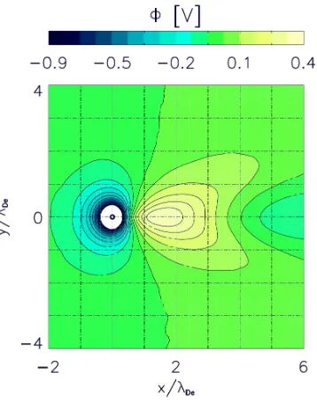
Figure 2.5: Wake field as it forms downstream a particle situated at (0,0). In this plot the ions stream from the left to the right. Downstream the negatively charged particle a positive potential forms. This is the so-called wake field which attracts other negatively charged particles and is responsible for string formation, [151].
Similar to the ion shadowing the neutrals can be shadowed by particles, as proposed by Fortov et al. [66]. If the gas temperature is smaller than the particle surface temperature the neutral shadowing force would be repulsive. In the opposite case the force is consid-ered to be attractive. The proposed attractive shadowing force could then overcome the repulsive electrostatic force at large distances.
The particle charge is determined by the flux of electrons and ions towards it. Due to the higher electron mobility they usually carry negative charges in the order of several thousand electron charges depending on their size. Around each particle a positive space charge (Debye sphere, see figure 2.6(a)) with a radius of the ion Debye length builds up. Thus, the interaction of particles in the bulk plasma are best described by screened Coulomb (Yukawa) interaction [159, 196].
The most important inter particle interaction in this thesis besides the screened Coulomb (Yukawa, see equation (1.6)) interaction is the wake field potential. Ions streaming past the inserted particles deform the Debye sphere around the particle. Downstream the particle the ions are focused, introducing a positive wake potential [91, 122, 123, 151, 199]. The shape of the wake field is shown in figure 2.5 as it has been taken from [151]. This non-reciprocal positive potential does not comply with Newtons third law leading to a situation in which the system can no longer be described by a Hamilton equation [34, 98, 108].
Figure 2.6: The potential distribution around a particle without any field (a), with the defor-mation due to the streaming ions (b) and in a time averaged reciprocal form due to an alternating electric field (c). This graphic is taken from [95]
either by strong lasers or by preceding electrons or ions [23].
The positive potential that forms downstream the particle attracts other negatively charged particles. Particle ensembles can form vertical strings [110, 122, 123], lanes [13, 95] or internal structures in clusters [92, 118] in response to the wake. Due to shadowing effects the charge of the lower particle is reduced. Thus, the focusing effect of the wake, depending on the particle charge, is reduced, too. This leads to an increase in the inner-string inter particle distance along a string. Charge depletion has been observed in particle clusters [22, 118] as well as in single strings [40, 41].
Since the wake field forms exclusively downstream the particle [22, 122, 139, 151] it is not reciprocal [107]. However, there exist possibilities to introduce a reciprocal deformation of the positive wake potential [33, 35, 95, 98]. In order to achieve this an alternating current with frequencies lower than the ion plasma frequency (see Equation 1.10) but higher than the dust plasma frequency4 has to be applied. A like-wise alternating electric field will have an impact on the ions but does not change the particle positions [34].
The time averaged deformation of the wake field in response to an electric field is displayed in figure 2.6 (c), [95]. It is compared to the non - distorted Debye sphere (a), as it usually occurs in the bulk plasma, and the deformation as in response to ions streaming past a negatively charged particle (b), as it usually occurs in the sheath region where the electric fields are very strong, [95]. It can be seen that in difference to the usual deformation caused by ions streaming only in one direction past the particle the wake potential is symmetric in case of applying an (additional) alternating current.
If an alternating electric field is applied to a particle cloud an orientation along the electric field axis is observed [95, 98]. The resulting system is called an ’electrorheological plasma’5. Similar situations have earlier been observed in colloids [192, 178, 217]. Next
to the alternation of orientation by electric fields comparative results can be gained by applying magnetic fields. A corresponding system is called magnetorheological system
4The dust plasma frequency is defined analogue to the ion and electron plasma frequency given in
Equation 1.10.
2.4 Particle Interactions 27
[211]. In line with the results from experiments on colloidal suspensions with electric fields alternating not only in one but in more dimensions (in-plane [133] and spherical rotating electric fields [170]) have been proposed.
Due to the tunable viscosity and electric and magnetic properties the advantages of like-wise systems can be used in medical as well as in industrial applications[45, 171, 198, 222]. Electrorheological systems differ from other systems with orientated dipoles. For in-stance the magnetic dipoles in unordered ferro magnetic systems are stochastically orien-tated but present if no external field is applied. Once such a magnet is subjected to a magnetic field the internal dipoles are orientated along the external field axis. However, the dipoles are never as perfectly aligned as in electrorheological systems. Furthermore, the dipoles are introduced by the additional field and not present before [34].
In electrorheological plasmas a particle and the positive wake potential behind it form a dipole. These dipoles are, due to the additional electric field, perfectly aligned. Thus the isotropic interaction potential (usually Yukawa interaction) has to be extended by an anisotropic potential due to dipole-dipole interaction, leading to the time averaged potential [34]:
V(r, θ) = Φi −ξΦaP2(cosθ). (2.15)
In this equation ξ gives the relative strength of the anisotropy. The anisotropic potential scales with
Φa ∝
M2
T
r3 . (2.16)
The angular distribution is best described by the Legendre polynomial
P2(cosθ) =
3 2cos
2θ− 1
2. (2.17)
It is an exact description if the dipoles are perfectly aligned along one well defined axis. If this is not the case Equation 2.15 will only describe the first approximation of the interaction potential.
As it has been shown by Kompaneets et al. [109] the isotropic interaction potential Φi
changes depending on the thermal Mach number:
MT =
Ion Drift Speed Ion Thermal Velocity =
ui
vT i
, (2.18)
Depending on the surrounding plasma the Mach number varies. In the bulk plasma, for instance, it is close to zero, whereas it increases in the sheath, where the ions are accelerated towards the electrode or the confining walls. If the thermal Mach number equals zero the isotropic potential is described by Yukawa interaction, if it equals one the best approximation is a Lennard-Jones potential:
ΦLJ ∝
σ r n −σ r m , (2.19)
with σ ∝ λD. In figure 2.7 the particle interaction for increasing Mach numbers is given.
Figure 2.7: Isotropic interaction potential for different Mach numbers [109].
fitted. A like-wise potential is often employed to describe the interaction potential between two atoms. It can be seen that even the isotropic interaction potential has an attractive part if the thermal Mach number is high enough [13, 109].
In the horizontal plane, parallel to the electrodes, the interaction is not dominated by the wake field effect but by an interplay of attractive and repulsive forces. In ground based experiments negatively charged particles of sufficient mass6 levitate in the sheath at
the height where the electric field balances gravitation. Assuming that further introduced particles are of the same mass and size as the initial one they will all carry the same charge7 and be therefore levitated at the same height in the plasma sheath. Due to their
charge, the electrostatic confinement, and their interaction potential these particles tend to organize themselves in 2D lattices. To describe the particle behavior a coupling parameter describing the ratio of the interaction potential and the kinetic particle energy can be introduced [88, 209]. If the kinetic particle energy is samller than the potential energy the system is called strongly coupled. Furthermore the occurring patterns in the particle arrangement (phase transitions) can be predicted by the coupling parameter. The more the interaction potential of neighboring particles exceeds the kinetic energy, the higher is the ordering in the system. Such ordered systems (2D plasma crystals) have been observed by Thomas et al. [204, 205], Chu et al. [46], and Hayashi et al. [79]. In further studies different crystalline structures as well as phase transitions have been observed in 2D and in 3D systems [50, 86, 103, 106, 167]. If the wake field is not changed a particle downstream a layer of other particles is situated in the center of the particle configuration upstream. Thus, the most common 3D crystal arrangements are fcc (face centered cubic) and hcp (hexagonal closed packed) structures, [86].
6Very small (light) particles will be distributed homogeneously over the plasma. This behavior can be
introduced also by using thermophoretic forces or by micro gravity experiments as for instance in drop tower experiments, parabolic flights, or on board the ISS.
7The charge and size distribution among the particles has at length been discussed above. However, for
2.5 Summary 29
2.5
Summary
Several different types of particles can be formed or artificially introduced into a plasma. The resulting system is then called a dusty or complex plasma. In the plasma particles are subjected to electron and ion fluxes. Due to the higher electron mobility the parti-cles tend to charge up negatively. Thus, the partiparti-cles are subjected to several different forces caused by gravitation and electric fields as well as by impacts of neutrals, ions, and electrons. Furthermore, additional forces can be introduced such as thermal gradients or electromagnetic fields. Around each particle a positive space charge, the so-called Debye sphere, forms, leading to a screened coulomb inter-particle interaction. If positive ions stream past a negative particle they are focused depending on the ion velocity. This leads to a deformation of the Debye sphere. Furthermore, the Debye sphere and thereby the particle interaction potential can be manipulated by additional fields.
2.6
R´
esum´
e
Plusieurs types de particules peuvent ˆetre synth´etis´ees ou inject´ees dans un plasma. Le syst`eme qui en r´esulte est d´enomm´e ”Plasma poussi´ereux” ou ”Plasma complexe”. D´es leur formation ou injection, les particules sont soumises aux flux des ´electrons et des ions arrivant `a leur surface. A cause de la grande mobilit´e des ´electrons, compar´ee `a celle des ions plus massifs, la charge acquise par les particules est n´egative. Elles sont par cons´equent soumises `a diff´erentes forces li´ees au champ gravitationnel, au champ ´electrique, aux collisions avec les esp`eces neutres, les ions et les ´electrons pr´esents dans le milieu plasma. Il aussi possibles de les soumettre `a d’autres forces telles celles li´es `a des champs ´
electromagn´etiques ou `a des gradients de temp´erature (thermophor`ese). Chaque particule est entour´ee d’une gaine de charges d’espace positives, appel´ee sph`ere de Debye, qui ´ecrante le potentiel ´electrique g´en´er´e par la charge qu’elle porte et ainsi affecte l’interaction entre particule. Selon leur vitesse, des ions positifs peuvent ˆetre d´evi´es, et focalis´es, par leur interaction avec les particules. Cela se traduit aussi par la d´eformation de la sph`ere de Debye. Ainsi, la sph`ere de Debye et par voie de cons´equence l’interaction entre particule peut ˆetre modul´ee `a l’aide de champs additionnels.
![Figure 1.1: The different regions (a) in a DC glow discharge and the distribution of the fieldsand space charges(b), [128].](https://thumb-us.123doks.com/thumbv2/123dok_us/8092160.1350648/23.612.209.389.114.376/figure-dierent-regions-discharge-distribution-eldsand-space-charges.webp)
![Figure 1.2: The graph demonstrates the U-I characteristics of a DC discharge, [128].](https://thumb-us.123doks.com/thumbv2/123dok_us/8092160.1350648/24.612.212.393.111.258/figure-graph-demonstrates-u-i-characteristics-dc-discharge.webp)
![Figure 1.3: Sketch of a radio frequency driven plasma(a). Plot (b) displays the distribution ofthe electron and ion density along the plasma and the sheath, [128]](https://thumb-us.123doks.com/thumbv2/123dok_us/8092160.1350648/25.612.107.492.106.327/figure-sketch-frequency-plasma-displays-distribution-electron-density.webp)
![Figure 1.4: Sketch of the electrical network of a radio frequency driven plasma with the matchingnetwork (a), [214]](https://thumb-us.123doks.com/thumbv2/123dok_us/8092160.1350648/26.612.101.495.96.233/figure-sketch-electrical-network-frequency-driven-plasma-matchingnetwork.webp)

![Figure 2.4: The prediction of OML, represented by the dotted line, compared to several simu-lation and measurements on the particle charge, [68].](https://thumb-us.123doks.com/thumbv2/123dok_us/8092160.1350648/36.612.207.394.106.282/figure-prediction-represented-dotted-compared-lation-measurements-particle.webp)
![Figure 2.7: Isotropic interaction potential for different Mach numbers [109].](https://thumb-us.123doks.com/thumbv2/123dok_us/8092160.1350648/44.612.211.391.111.259/figure-isotropic-interaction-potential-for-dierent-mach-numbers.webp)
![Figure 3.2: Chemical reactions during nucleation. They are caused by association, dissociation,ionization, and attachment, [54].Further possible reactions leading to similar results can befound e.g](https://thumb-us.123doks.com/thumbv2/123dok_us/8092160.1350648/49.612.157.445.108.384/chemical-reactions-nucleation-association-dissociation-ionization-attachment-reactions.webp)