Fuzzy Logic Controller based Energy Storage System for Micro
Grids Integration
Y.Ramanjaneyulu
1, N.Devasena
21PG Scholar, Department of EEE, VEMU Institute of technology, P.Kothakota, A.P, India Email: [email protected]
2 Assistant Professor, Department of EEE, VEMU Institute of technology, P.Kothakota, A.P, India Email: [email protected]
Abstract- This project proposes a fuzzy based for HESS micro grids integration for power quality improvement. The system incorporates clean energy generation along with power quality improvement thus increasing functionality of the system. Rising demand for distributed generation based on Renewable Energy Sources (RES) has led to several issues in the operation of utility grids. The microgrid is a promising solution to solve these problems. A dedicated energy storage system could contribute to a better integration of RES into the microgrid by smoothing the renewable resource’s intermittency, improving the quality of the injected power and enabling additional services like voltage and frequency regulation. However, due to energy/power technological limitations, it is often necessary to use Hybrid Energy Storage Systems (HESS).In this paper the use of a 4-Leg 3L-NPC power converter topology to interface a RES with a HESS (formed by a VRB and a Li-Ion battery) in a microgrid context has been investigated. A new model of the structural limits is presented and implemented to exploit the entire capability of the 4-Leg 3L-NPC converter to insure a maximum power division between the two ESS. A non-linear 2-SMC scheme has been designed and tuned to control the zero sequence injection in the modulating signals in order to control the power flow of the HESS. Simulation and experimental results proved the capacity of the proposed control strategy to manage a HESS in order to improve the power quality and stability as well as to control the renewable energy injected into a microgrid. The investigation of the limits of the topology showed a power exchange capability among this fuzzy enables its application to control in conditions of distorted voltages. The proposed method is verified by simulating the system in Matlab 2013a Simulink with combination of linear and nonlinear loads.
Index terms – DC-AC power converters, Energy
storage, Microgrids, Power quality, Sliding mode control
I. INTRODUCTION
THE increasing penetration of DG is changing management of the grid from centralized to decentralized schemes, creating several challenges that must be carefully addressed in order to keep the electrical grid’s proper operation High penetration of renewable energy can lead to stability and power quality issues due to the stochastic nature of RES, such as wind and solar energy. The microgrid concept, which can be defined as a small scale weak electrical grid that is able to operate both in connected and islanded mode, has been extensively studied as a solution for RES integration. The weak nature of a microgrid implies the use of an Energy Storage System (ESS) to increase RES penetration and insure its stability [1]–[3].
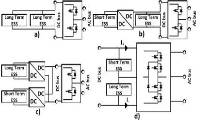
The use of an ESS integrates constraints such as admissible bandwidth, maximum ratings, current/power maximum gradient and the number of cycles. If these constraints are not respected it can lead to a dramatic lifetime reduction of the ESS, or in certain cases, to its destruction. [4], [5]. The use of a Hybrid Energy Storage System (HESS) offers the necessary trade-off for increasing the lifetime of each ESS while also increasing the global specific energy and power of the whole system [6], [7]. Fig. 1 shows the main structures currently found in the literature to integrate a HESS into a grid. The passive topology
best flexibility but the use of several DC/DC converters affects the global efficiency [13]. Finally, despite a lower flexibility when compared to the
parallel topology, the 3L-NPC topology d) can be used as a single power converter able to manage the power flow of a HESS, acting as an interface between the RES and the grid.
Figure. 1 Power converter topologies for micro grid ESS hybridization passive (b) floating (c) parallel (d)
3L-NPC topology
Due to the reduced voltage applied on the switches and an increased number of voltage levels, the 3L-NPC topology becomes more efficient while showing a lower current Total Harmonic Distortion (THD) [13] than an equivalent two level inverter. Several works have been carried out on ESS hybridization using multilevel topologies, including the 3 Leg 3L-NPC [13]–[15]. In [13], a PI controller is designed to control the power flow of a Vanadium Redox Flow Battery (VRB) whereas a Super Capacitor (SC) provides the fast variation of power with both parallel and 3 Leg 3L-NPC inverters. It is shown that, beyond the limits of the 3L-NPC topology, the efficiency and THD improvement make this topology suitable for ESS hybridization.
Another particularity of this topology is the floating DC link middle point voltage which involves voltage ripples at three time the fundamental frequency (i.e. 150 Hz) [16]–[20]. The harmonic magnitudes are directly linked to the modulation technique used, as well as the DC link filter characteristics [21], [22]. These voltage ripples coupled to highly unbalanced AC loads may cause large DC current harmonics which may increase electromagnetic interference (EMI) and impact ESSs lifetime due to increased thermal losses [23], [24]. This effect could be exacerbated by a degraded DC link
filter. The 4-Leg 3L-NPC used as an active power filter is also extensively studied in the literature [19], [25]– [28]. Thanks to the 4th leg this inverter is able to produce zero sequence currents in addition to direct and negative ones. This characteristic enables compensation for the increasing number of unbalanced loads (monophasic customers, electric vehicles…) and single phase generators (small wind/PV units).
In [19], [27], [29] several modulation techniques and redundant vector selection methods are used to balance the capacitor voltages in power filter application. In [27], the AC side predictive control of a 4 Leg 3L-NPC inverter in isolated mode improves the performance and the power quality. In [30] a non-linear control strategy is developed for a 4 Leg 3L-NPC inverter used as an active power filter. However, the 4-Leg 3L-NPC inverter used both as a power filter and a HESS interface for a RES integration into the grid is not addressed in the literature. The use of the 4-Leg 3L-NPC topology when associated with an adapted control strategy in a micro grid context presents itself as a promising solution due to its ability to combine the following characteristics: • Increase the efficiency of RES and HESS integration to the microgrid through a unique power electronics interface acting as an active power compensator able to smooth the RES by acting on the HESS [13]
• Reduce AC side current harmonics (for the same switching frequency and AC filter components when compared to a 2 level inverter) [31]
• Reduce HESS current harmonics caused by the floating middle point inherent to the NPC topology and move the ripples involved by unbalanced AC loads to the high specific power ESS [32]
• Compensation of AC side microgrid disturbances produced by unbalanced/nonlinear loads thanks to the fourth leg [19]
power sharing between the two ESSs and the RES, and at the same time improve the AC side power quality. The main contribution of this paper lays in the DC power flow controller which allows HESS power flow control and DC current harmonics suppression. The new model for 4-Leg 3L-NPC structural limits proposed in [33] is assessed. The effectiveness of the proposed system has been tested through simulations and experimental tests using a laboratory prototype.
II.EXISTING SYSTEM
1. HESS AND 4-LEG 3L-NPC MODELING
In order to design and assess in simulation a control strategy able to manage the DC power flow within the HESS and at the same time improve the AC power quality, the investigated system has first been modeled, taking into account the objective of the study, i.e. the transient behavior.
A. Modeling of the ESSs
The investigated HESS is formed of a Li-Ion battery and a VRB. The VRB technology benefits from the decoupled specific power (which depends on the stack characteristics) and its specific energy (which depends on volume of electrolyte tanks). Along with the flexibility offered by this specificity, the technology is also suited to long term energy storage as there is nearly no self-discharge with a good round trip efficiency of 78%-88% [34]. The Li-Ion battery benefits from a high specific power and moderate self-discharge (1-5% per day). This technology has also been developed for high power standalone applications in recent years [35]. Consequently, the use of these two technologies is complementary and realizes a high specific energy and high specific power HESS.
A. Li-Ion model
The Li-Ion model used in this work is based on the module presented in [39]. This model is already implemented in MATLAB/Simulink within the Sim Power Systems library. The battery is realized with strings of series modules connected in parallel to build an ESS of 825 V/ 30Ah (at 80% of SOC and open circuit).
2. Modeling of the 4-Leg 3L-NPC
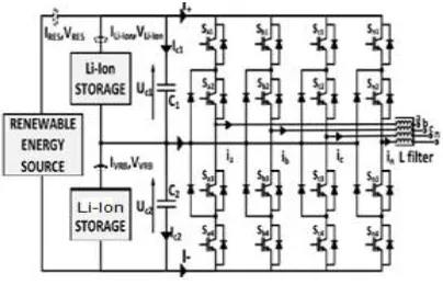
Fig. 4 shows the schematic representation of the 4-Leg 3LNPC inverter used as a HESS interface for RES and HESS integration to a microgrid. This topology requires the RES to be a current source and in particular, could be adapted if placed either after a Maximum Power Point Tracking (MPPT) converter for a solar plant, or instead of the grid-side converter of a back to back set up for wind turbines. For this study the RES is considered as a current source injecting into the DC bus.
Figure.2 4-Leg 3L-NPC topology used as a HESS/RES interface
The 4-Leg 3L NPC inverter has 34 = 81 different switching states that produce different voltage vectors defined by (3). The vectors generated by more than one switching state are called redundant vectors and allow power flow sharing control among the HESS .
III.PROPOSED METHOD
A. Block Diagram
A new model of the structural limits is presented and implemented to exploit the entire capability of the 4-Leg 5L-NPC converter to insure a maximum power division between the two ESS. A non-linear 2-SMC scheme has been designed and tuned to control the zero sequence injection in the modulating signals in order to control the power flow of the HESS.
Figure.3 proposed block diagram
Fuzzy Logic is a particular area of concentration in the study of Artificial Intelligence and is based on the value of that information which is neither definitely true nor false. The information which humans use in their everyday lives to base intuitive decisions and apply general rules of thumb can and should be applied to those control situations which demand them. Acquired knowledge can be a powerful weapon to combat the undesired effects of the system response.
In most applications, there are some points which lie in the common area. Information which lies within the common area has to be studied, stored, and used to quantify and to classify the data. This allows for smart manipulation of the data structure in order to make inference to a solution. Information which falls in that common area can be ranked, aged, and "best guess" made after evaluation of this "gray" information. Another advantage of Fuzzy Logic controllers is to quantify the input signal in a sometimes "noisy" environment. This noise, which tends to corrupt the integrity of the actual signal, is dealt with through the common sense of the competent operator. Mathematically, the information must be judged and prepared for use in decision making. If an operator took the time to plot the process information on an X-Y coordinate system, the operator could visually apply a curve fit to the data and come up with a fairly accurate generic representation
Mathematically, fitting a curve of lower order would produce a fairly inaccurate representation. Therefore, a higher order curve fit would be appropriate to accommodate the noisy signal. Fuzzy Logic attempts to emulate what the human response would be and apply the most intelligent fit to the data. Conventional computing is based on Boolean logic, meaning everything is represented as either zero or one.
In some situations this leads to oversimplification and inadequate results. Fuzzy logic controllers, and by extension, fuzzy control, seeks to deal with complexity by creating heuristics that align more closely with human perception of problems.
Fuzzy logic provides a way of dealing with imprecision and nonlinearity in complex control situations. Inputs are passed to an “inference engine” where human or experienced-based rules are applied to produce an output.
The proposed DDSRF current controller scheme is shown in Figure 5. The dc value of one sequence is the value for the opposite sequence oscillation´samplitude. On the other hand, the Park´s transformation is applied over the angular position difference of both frames with the aim of obtaining the estimated oscillation waveform. The DDSRF current controller filters the corresponding opposite sequence current to obtain its dc value and decelerate (if the sequence to be compensated is the positive one) or accelerate (if the sequence to be compensated is the negative one) by two times the rotating frequency (considering also the initial voltage phase shift) in order to estimate the undesirable oscillations. The low-pass (LP) filter for obtaining the mean value does not have a high selectivity because in steady-state conditions, the decoupled current is free from oscillations and matches its dc value.
IV SIMULATION WITH FUZZGY CONTROLLER AND RESULTS
(a)
(b)
Fig 5 (a) Li-Ion and VRB current harmonics for different Zero Sequence injection regulation (b)
Li-Ion b) VRB current harmonics for different Zero Sequence injection regulation (Red – 2-SMC regulated zero sequence and Blue – Fuzzy regulated
zero sequence)
Above Figure presents the HESS currents for different zero sequence injection controls. The Fuzzy scheme allow a significant improvement of the current harmonics suppression compared to the 2-SMC. Also, the better result of the VRB harmonic suppression compared to the Li-Ion one are due to the fact that only the VRB current is controlled through zero sequence injection.
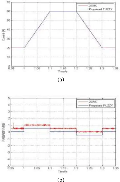
A. Dynamic performance comparison (a) currents (b) errors
(a)
(b)
Figure.6 (a) Dynamic performance comparison currents (b) Dynamic performance comparison
errors
Fig. 5 shows the results obtained for VRB current reference ramp of 4A/ms from 20A To 60A. As can be seen, the Fuzzy scheme shows better tracking ability and DC harmonics reduction compared to the 2- SMC Scheme. The maximum absolute error for the Fuzzy strategy being under 0.5A illustrates the good performance compared to the 2- SMC strategy that reaches more than 0.5A error.
(a)
(b)
Figure.7 (a) Dynamic performance comparison while parametric uncertainties currents (b) Dynamic
performance comparison while parametric uncertainties errors
In order to assess the parametric robustness of the two control schemes, the DC bus link capacitances C1 and C2 have been decreased by 50%, while the series resistor of the VRB has been increased by 50% with both 2-SMC and PI gains kept at their previous settings.
In Fig.7 the results of a ramp of 4A/ms from 20A to 60A on the VRB current reference are displayed. It can be seen that the dynamics of the error for the Fuzzy Scheme is much closer to the performance observed without parametric uncertainties compared to the 2-SMC scheme. It can be concluded from these simulation results that the Fuzzy design and tuning process is suitable both in terms of dynamic performance and in terms of robustness.
TOTAL HARMONIC DISTORTION
(a)
Figure.8 (a) The total harmonic distortions values in case 2-SMC controller. (b) The total harmonic
distortions values in case Fuzzy controller
Fuzzy controller instead of 2-SMC controller is to improve the better power quality, low THD, high efficiency and its ability to manage the unbalanced loads.
V CONCLUSION
Hence we have conclude that the Simulation results proved the capacity of the proposed control strategy to manage a HESS in order to improve the power quality and stability as well as to control the renewable energy injected into a micro grid. The investigation of the limits of the topology showed a power exchange capability among this fuzzy enables its application to control in conditions of distorted voltages. Here THD Current value is 3.24% getting in proposed method. Hence proposed method performance is improved than the existing method.
VI FUTURE SCOPE
current threshold values. Instead of fuzzy controller, we can use ANN for better results.
VII REFERENCES
[1] M. Yekini Suberu, M. Wazir Mustafa, and N. Bashir, “Energy storage systems for renewable energy power sector integration and mitigation of intermittency,” Renew. Sustain. Energy Rev., vol. 35, pp. 499–514, Jul. 2014.
[2] S. Vazquez, S. M. Lukic, E. Galvan, L. G. Franquelo, and J. M. Carrasco, “Energy Storage Systems for Transport and Grid Applications,” IEEE Trans. Ind. Electron., vol. 57, no. 12, pp. 3881– 3895, Dec. 2010.
[3] M. G. Molina and P. E. Mercado, “Power Flow Stabilization and Control of Microgrid with Wind Generation by Superconducting Magnetic Energy Storage,” IEEE Trans. Power Electron., vol. 26, no. 3, pp. 910–922, Mar. 2011.
[4] M.-E. Choi, S.-W. Kim, and S.-W. Seo, “Energy Management Optimization in a Battery/Supercapacitor Hybrid Energy Storage System,” IEEE Trans. Smart Grid, vol. 3, no. 1, pp. 463–472, Mar. 2012.
[5] G. Qiu, C. R. Dennison, K. W. Knehr, E. C. Kumbur, and Y. Sun, “Porescale analysis of effects of electrode morphology and electrolyte flow conditions on performance of vanadium redox flow batteries,” J. Power Sources, vol. 219, pp. 223–234, Dec. 2012.
[6] X. Tan, Q. Li, and H. Wang, “Advances and trends of energy storage technology in Microgrid,” Int. J. Electr. Power Energy Syst., vol. 44, no. 1, pp. 179–191, Jan. 2013.
[7] N. R. Tummuru, M. K. Mishra, and S. Srinivas, “Dynamic Energy Management of Renewable Grid Integrated Hybrid Energy Storage System,” IEEE Trans. Ind. Electron., vol. 62, no. 12, pp. 7728–7737, Dec. 2015.
[8] T. A. Smith, J. P. Mars, and G. A. Turner, “Using supercapacitors to improve battery performance,” in 2002 IEEE 33rd Annual IEEE Power Electronics Specialists Conference. Proceedings, 2002, vol. 1, pp. 124– 128.
[9] R. A. Dougal, S. Liu, and R. E. White, “Power and life extension of battery-ultracapacitor hybrids,” IEEE Trans. Components Packag. Technol., vol. 25, no. 1, pp. 120–131, Mar. 2002. [10] T. Zhou and B. François, “Energy management and power control of a hybrid active wind generator for distributed power generation and grid integration,” IEEE Trans. Ind. Electron., vol. 58, no. 1, pp. 95–104, Jan. 2011.
[11] Z. Guoju, T. Xisheng, and Q. Zhiping, “Research on Battery Supercapacitor Hybrid Storage and its application in MicroGrid,” in Asia-Pacific Power and Energy Engineering Conference, APPEEC, 2010, pp. 1–4.
[12] H. Babazadeh, W. Gao, and X. Wang, “Controller design for a Hybrid Energy Storage System enabling longer battery life in wind turbine generators,” in 2011 North American Power Symposium, 2011, pp. 1–7.
[13] A. Etxeberria, I. Vechiu, H. Camblong, and J.-M. Vinassa, “Comparison of three topologies and controls of a hybrid energy storage system for microgrids,” Energy Convers. Manag., vol. 54, no. 1, pp. 113–121, Feb. 2012.
[14] S. D. G. Jayasinghe and D. M. Vilathgamuwa, “Hybrid cascaded multilevel inverter with supercapacitor energy storage for grid integration of renewable energy systems,” in Power Electronics and Drive Systems (PEDS), 2015 IEEE 11th International Conference on, 2015, pp. 732–739.
[15] S. S. G. Jayasinghe, D. M. Vilathgamuwa, and U. K. Madawala, “DiodeClamped Three-Level Inverter-Based Battery/Supercapacitor Direct Integration Scheme for Renewable Energy Systems,” IEEE Trans. Power Electron., vol. 26, no. 12, pp. 3720–3729, Dec. 2011.
[16] H. Zhang, S. J. Finney, A. Massoud, and B. W. Williams, “An SVM Algorithm to Balance the Capacitor Voltages of the Three-Level NPC Active Power Filter,” IEEE Trans. Power Electron., vol. 23, no. 6, pp. 2694–2702, Nov. 2008.
[17] D. Zhang, F. Wang, R. Burgos, R. Lai, and D. Boroyevich, “DC-Link Ripple Current Reduction for Paralleled Three-Phase Voltage-Source Converters With Interleaving,” IEEE Trans. Power Electron., vol. 26, no. 6, pp. 1741–1753, Jun. 2011.
[18] P. Acuña, L. Morán, M. Rivera, R. Aguilera, R. Burgos, and V. G. Agelidis, “A Single-Objective Predictive Control Method for a Multivariable Single-Phase Three-Level NPC Converter-Based Active Power Filter,” IEEE Trans. Ind. Electron., vol. 62, no. 7, pp. 4598–4607, Jul. 2015.
About Authors
1. Mr.Y. Ramanjaneyulu, He received the B. Tech (Electrical and Electronics Engineering) degree from GRIET College Affiliated to JNTU Hyderabad in 2011 and the M.Tech (Power Electronics & Electrical Drives) pursuing in Vemu Institute of Technology, Affiliated to JNTU Anantapuramu.
His interested subjects are Power Electronics, Electrical drives etc.
2. Mrs .N Devasena, she received B. Tech (Electrical and Electronics Engineering) degree from Narayana Engineering College, GUDUR. Affiliated to JNTU anantapuramu and the M.Tech Degree in Electrical Power
Engineering from SITAMS