85
Analysis of Plastic Helical Gear Set in Mesh Using
FEM tool ANSYS at Varying Loads
Chetan G. Dhangar
1, Sandip S. Patil
2, Deepak K.Patil
3,
Mechanical Engg.1, 2, 3, GCOE&RC1, 2 SIP 3Email: [email protected]1, [email protected]2, [email protected]3
Abstract- Design of gear is important in transmission system and optimizing the design criteria affects the
performance of system. In mechanical power transmission systems gears are one of the most critical components. The bending and surface strength of the gear tooth are considered to be one of the main contributors for the failure of the gear in a gear set. Thus, analysis of stresses has become popular as an area of research on gears to minimize or to reduce the failures and for optimal design of gears. This study work mainly focused on the characteristics of an in-volute helical gear system where contact stresses and Strains are considered. To estimate the various Stresses, Strains and other important parameters of helical gears a three-dimensional solid model for different number of teeth are generated by Pro/Engineer that is powerful and modern solid modeling software and the numerical solution is done by ANSYS, which is a finite element analysis package. The analytical investigation is done by varying the load on gear for stress and strain analysis of helical gear design
Index Terms- FEA, In-volute helical gear, ANSYS, Shear stress, Shear Strain
1. INTRODUCTION
A gear is a rotating machine part having cut teeth, or cogs, which mesh with another toothed part in order to transmit torque. Two or more gears working in tandem are called a transmission and can produce a mechanical advantage through a gear ratio and thus may be considered a simple machine. Geared devices can change the speed, torque, and direction of a power source. The most common situation is for a gear to mesh with another gear, however a gear can also mesh a non-rotating toothed part, called a rack, thereby producing translation instead of rotation.
• Power transmission is the movement of energy from its place of generation to a location where it is applied to performing useful work
• A gear is a component within a transmission device that transmits rotational force to another gear or device
Fig 1: Simple Helical Gear Drive
In a helical gear the leading edges of the teeth are not parallel to the axis of rotation, but are set at an angle as shown in Fig.1. Since the gear is curved, this angling causes the tooth shape to be a segment of a helix. Helical gears can be meshed in a parallel or crossed orientations.
1.1. Problem Definition
Gears can fail in many different ways, and except for an increase in noise level and vibration, there is often no indication of difficulty until total failure occurs. In general, each type of failure leaves characteristic clues on gear teeth, and detailed examination often yields enough information to establish the cause of failure. The general types of failure modes (in decreasing order of frequency) include fatigue, impact fracture, wear and stress rupture. Fatigue is the most Common failure in gearing. Tooth bending fatigue and surface contact fatigue are two of the most common modes of fatigue failure in gears. Several causes of fatigue failure have been identified. These include poor design of the gear set, incorrect assembly or misalignment of the gears, overloads, inadvertent stress raisers or subsurface defects in critical areas, and the use of incorrect materials and heat treatments.
2. SUGGESTED METHODOLOGY
This can be avoided or minimized by proper method analysis and modification of the different gear parameters. In view of this the main purpose of this thesis is by using FEA tool ANSYS to develop theoretical model of helical gear in mesh and to determine the effect of gear stresses. A study approach towards the helical gear analysis is shown in Fig. 2.
The main focusing areas of this Research are described as follow:
86 Develop and determine models of contact
elements, to analysis contact stresses using ANSYS.
[image:2.595.102.278.189.327.2]Generate the profile of helical gear teeth model to calculate the effect of gear under different loading conditions.
Fig 2: Study Approach for Helical Gear Analysis
2.1. General Procedures to Create an In-volute Curve
The sequence of procedures employed to generate the in-volute curve are illustrated as follows:
A. Set up the geometric parameters
Number of teeth Diametric Pitch Pressure angle Pitch diameter Face width Helix angle
B. Create the basic geometry such as addendum,
dedendum and pitch circles in Support of the gear tooth.
C. Define the involute tooth profile with datum
curve by equation using cylindrical coordinate system.
D. Create the tooth solid feature with a cut and
extrusion. Additional helical datum curves are also required in this step to sweep helical gear teeth.
E. Pattern the tooth around the centre line axis.
The key specifications of geometrical parameters and the helical gear model of helix angle 20 degree developed by using the above procedures in Pro/Engineer are shown in and Table 1 and Fig. 3
3. Stress Strain Analysis:
Deformations are calculated relative to the part or assembly world coordinate system.
[image:2.595.308.519.226.733.2]The three component deformations Ux, Uy, and Uz, and the deformed shape U are available as individual results.
[image:2.595.326.505.611.720.2]Fig 3: Directional Deformation
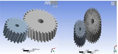
Fig 3:Solid Meshing of Plasic Helical Gear
a)Total deformation of two Plastic helical gear
b) Directional deformation(X axis) of two Plastic helical gears
c) Equivalent elastic strain of Plastic helical gear
[image:2.595.75.266.654.742.2]87
3.1. STRAIN ENERGY
The external work done on an elastic member in causing it to distort from its unstressed state is transformed into strain energy which is a form of potential energy. The strain energy (ε) in the form of elastic deformation is mostly recoverable in the form of mechanical work. Shear and strain analysis ANSYS results are as shown in Fig 4.
The actual strain at a point as a result of a tensile load is established by considering a small length change ∆δ of small part of the original length ∆L . The strain is ∆δ as ∆L >0.
[image:3.595.308.552.155.764.2]ε = lim∆L ->0∆δ /∆ L = dδ /d
Table 1: Considerations for design of Helical Gear
Sr. no
Geometry
Name Gear 1 Gear 2
1 No. of teeth 20 32
2 RPM 10000rpm 10000 rpm
3 Rotational velocity
200 radian per sec
200 radian per sec
4 Diameter pitch 200 mm 300 mm
5 Addendum 220 mm 320 mm
6 Dedendum 180 mm 278 mm
7 Face width 6.67 mm 7.104 mm
8 Material type Polyethyle ne
Polyethylen e
3.2. STRESS INTENSITY
The stress intensity factor, K, is used in fracture mechanics to predict the stress state ("stress intensity") near the tip of a crack caused by a remote load or residual stresses. It is a theoretical construct usually applied to a homogeneous, linear elastic material and is useful for providing a failure criterion for brittle materials. The concept can also be applied to materials that exhibit small-scale yielding at a crack tip.
Hook's law for an elastic material is that the strain is directly proportional to the stress. The constant of proportionality is called Young's Modulus (E)
σ = E*ε
Analysis result for Plastic helical gear set and 1 KN to 10 KN stress analysis results are shown in Table 2 and Fig 5 respectively
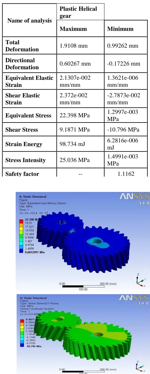
Table 2: Analysis result for Plastic helical gear set
Name of analysis
Plastic Helical gear
Maximum Minimum
Total
Deformation 1.9108 mm 0.99262 mm
Directional
Deformation 0.60267 mm -0.17226 mm
Equivalent Elastic Strain
2.1307e-002 mm/mm
1.3621e-006 mm/mm
Shear Elastic Strain
2.372e-002 mm/mm
-2.7873e-002 mm/mm
Equivalent Stress 22.398 MPa 1.2997e-003
MPa
Shear Stress 9.1871 MPa -10.796 MPa
Strain Energy 98.734 mJ 6.2816e-006
mJ
Stress Intensity 25.036 MPa 1.4991e-003
MPa
Safety factor -- 1.1162
[image:3.595.67.287.304.516.2]88
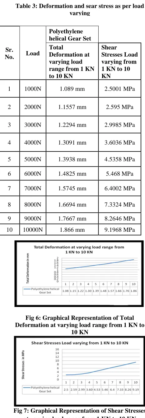
Table 3: Deformation and sear stress as per load varying
Fig 6: Graphical Representation of Total Deformation at varying load range from 1 KN to
10 KN
Fig 7: Graphical Representation of Shear Stresses at varying load range from 1 KN to 10 KN
Fig 8: Shear stress of polyethylene helical gear set at 10 KN
Deformation and sear stress as per load varying from 1KN to 10 KN is tabulated in Table 3and graphically ploted as per the readings and is shown in Fig 6 and Fig 7
Conclusion
This study concludes that the plastic gears are also shows effective results for light duty operations as compared to normal gear which results into minimize cost and weight in sundry applications
• At varying load it was found that the stresses in high density polyethylene or plastic helical gear set are low in the same manner the same things repeat in case of various strains hence it can be concluded that from the obtained results that plastic gears can be used at various sundry applications where low stresses are present in place of metallic gear for smoother and noiseless operations.
• Based on the results from the contact stress analysis the concerned factor for the plastic helical gear are to resist pitting failure. So this paper recommends that the use of polyethylene helical gear set is better to use in Small gear sets. • In this study the maximum bending stress
decreases with increasing face width and based on this finding if the material strength value is criterion then a gear with any desired helix angle with relatively larger face width is preferred.
REFERENCES
[1] Vijayarangan, S., and Ganesan, N.( 1993): A Static Analysis of Composite Helical Gears Using Three-dimensional Finite Element Method, Computers & Structures, 49, pp.253- 268,.
Sr.
No. Load
Polyethylene helical Gear Set Total
Deformation at varying load range from 1 KN to 10 KN
Shear
Stresses Load varying from 1 KN to 10 KN
1 1000N 1.089 mm 2.5001 MPa
2 2000N 1.1557 mm 2.595 MPa
3 3000N 1.2294 mm 2.9985 MPa
4 4000N 1.3091 mm 3.6036 MPa
5 5000N 1.3938 mm 4.5358 MPa
6 6000N 1.4825 mm 5.468 MPa
7 7000N 1.5745 mm 6.4002 MPa
8 8000N 1.6694 mm 7.3324 MPa
9 9000N 1.7667 mm 8.2646 MPa
[image:4.595.307.522.81.235.2]89 [2] Litivin, F., Perez, I.G., Fuentes, A., Vecchiato,
D., and Thomas, M.S. (2005): Generalized Concepts of meshing and Contact of involute Crossed Helical Gears and its Application, Compu. Methods & Appli. Eng., 194, pp.3710-3745.
[3] Wagaj, P., and Kahraman, A.( 2002): Impact of Tooth Profile Modifications on the Transmission error Excitation of Helical Gear Pairs, 6th Biennial Conference on Engineering Systems Design and Analysis, Istanbul-Turkey.
[4] Purkar T Sanjay and Sunil Pathak (2012): Aspect of Finite Element Analysis Methods for Prediction of Fatigue Crack Growth Rate, Res. J. Recent Sci, Vol. 1(2), 85-91.