Comparative Analysis of PI based and Fuzzy
Logic based UPQC
Trilok Kumar Tudu 1 , Dr. Prasanta Kumar Satpathy 2
P.G. Student, Department of Electrical Engineering, CET, Bhubaneswar, Odisha, India 1
Professor, Department of Electrical Engineering, CET, Bhubaneswar, Odisha, India 2
ABSTRACT: Power quality issues has become a day to day problem in power system. Unified power quality conditioner (UPQC) is the device which can be used to mitigate various voltage and current related problems simultaneously hence as considered as the best solution for mitigating various power quality issues. UPQC design is based on the using both series and shunt active power filters. Series part deals with the voltage related problems and shunt part deals with current related problem. In this thesis more emphasis is given in dealing with current harmonics and a comparative analysis is made between PI based and Fuzzy logic based UPQC.
KEYWORDS: Power quality issues, Active power filters, UPQC, PI controller, Fuzzy logic controller.
I.INTRODUCTION
In an electrical engineer perspective Power system is dynamic in nature. Not a day goes by that our power system is interrupted due to various power quality issues like voltage sag, voltage swell, current and voltage harmonics etc. Various FACTS devices are designed to mitigate these problems like DVR, STATCOM, Active power filters etc. UPQC is the device that can be used for mitigation of both voltage and current related issues. The best part of UPQC is that it can simultaneously mitigate both current and voltage related problems. One of the most important issues is the current harmonics and it happens due to extensive use of nonlinear loads. Nonlinear loads makes the waveform of the current distorted if this persists in the power system for longer period of time then could lead to damaging of the sensitive loads. The main objective of UPQC used here is to mitigate current harmonics by making the current waveform perfectly sinusoidal while the system is subjected to nonlinear loads.
II.RELATED WORK
The concept of UPQC was taken from L. Gyugyi [1] where he explained about the UPQC its work and benefits and
how it can be used to mitigate voltage and current relatedproblems. The controlling action of the UPQC is based on
paper explained by H. Akagi et al. [2] which uses the PQ based theory to calculate reference current needed for the mathematical modelling of UPQC.V. Khadkikar, P. Aganval, A. Chandra [3] proposed a technology based on unit vector template generation from distorted input supply is used for solving problems related with voltage and current harmonics in a basic UPQC model.I.Axente [4] has shown control strategy dealing with the series inverter controller where amplitude modulation ratio of series inverter sinusoidal PWM voltage controller is regularly adjusted to follow the actual dc link voltage and not the reference dc link voltageFuzzy logic based controller for the shunt active power filter by Jain S. K et al. [5] has described about implementation of fuzzy in UPQC so as to find better and accurate solution as compared to PI based UPQC.
III.UPQC
Unified Power Quality Conditioner (UPQC) is based on design using both series and shunt active filters. The main purpose of active power filter is to inject current into the system with same frequency but in reverse phase in order to cancel out the harmonics. The mathematical equations are all based on instantaneous power theory or the PQ theory. The PQ theory is based on Clark’s transformation where a three phase current is converted to 2 phase stationary
Fig. 1 Block diagram of UPQC
reference frame. The PQ theory is designed so as to calculate the reference current for the UPQC which is the deciding factor for the performance of UPQC.
In shunt control strategy the source voltage (VS) and load current (IL) are used to calculate active power (P) and
reactive power (Q). The source voltage (VS) which is in 3 phase is converted to 2 phase by applying Clark’s
transformation technique to get Vα and Vβ values. The PI controller is used to compare reference voltage Vdcref with the
voltage flowing across the capacitor Vdc, the output of the PI controller is the power lost proportional to the error
produced by comparing Vdc and Vdcref. Using PQ theory we can calculate the reference current which is in αβ (Iα, Iβ)
coordinates. Using inverse Clark’s transformation we can find reference current in abc (Ia, Ib, Ic) coordinate. The
reference current (Ia, Ib, Ic) is compared with the current flowing via shunt controller and the result is passed through
hysteresis controller to produce gate signals for the IGBTs present inside the shunt inverter to produce harmonic free current.
In series control strategy a comparison between source voltage (VS) and load voltage (VL) is made. Any differences
between the two will give us the amount of voltage that is needed to be fed back to the system. First both the voltages
are converted to its αβ coordinates. And hence find the voltage needed to be fed back to the system which will be in αβ
coordinates too. A PLL (phase lock loop) is used to run the system in same frequency throughout the entire system. Then we will find the magnitude and phase of the voltage found earlier. Reference voltage (Va, Vb, Vc) is calculated.
the current flowing via series controller and the output passed through hysteresis controller to produce gating signal for series inverter.
Fuzzy logic controller is somewhat similar to human thinking ability. The best thing about fuzzy is that it uses soft computing techniques as result we don’t have to worry anymore about mathematical calculations. The complex process of determining the gain values of the PI controller is eliminated. Using of fuzzy makes the system robust. The crisp values of fuzzy is converted to fuzzy value in fuzzification process. Fuzzy values are categorized in form of triangular membership function, it is the range of values defining the degree of belongingness. We can take many membership functions overlapping partially over each other. The fuzzy has to follow the rules which is user defined. The output of the fuzzy logic controller is based on the error and change in error of the membership function. After rule evaluation we get the fuzzy value and needed to be converted to crisp value by defuzzification process so as to get the final output.
ce e
NL NM NS EZ PS PM PL
NL NL NL NL NL NM NS EZ
NM NL NL NL NM NS EZ PS
NS NL NL NM NS EZ PS PM
EZ NL NM NS EZ PS PM PL
PS NM NS EZ PS PM PL PL
PM NS EZ PS PM PL PL PL
PL EZ PS PM PL PL PL PL
Table 1 Fuzzy Rules
The table above shown represents the fuzzy rules for the fuzzy logic controller. Where NL (Negative Large), NM (Negative Medium), NS (Negative Small), EZ (Zero), PS (Positive Small), PM (Positive Medium), PL (Positive Large) are the membership functions for error (e) and change in error (ce) of the fuzzy logic controller.
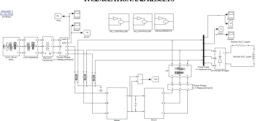
IV.SIMULATION AND RESULTS
A 33kV, 50Hz grid supply is provided to the nonlinear load via transmission line having its own impedance through stepdown transformer as shown in Fig. 2. Series VSI is connected to the transmission line through insertion transformer and shunt VSI is connected near load side. Both series and shunt VSI is connected via a common DC link capacitor which has reference voltage of about 600V. Shunt controller has the Fuzzy logic controller. Series controller has PLL block maintaining a constant frequency of about 50Hz.Below shown are the simulation results for power system when subjected to various conditions like current waveform when power system subjected to nonlinear loads, waveform for using PI based UPQC for mitigation of current harmonics and waveform for Fuzzy logic based UPQC.
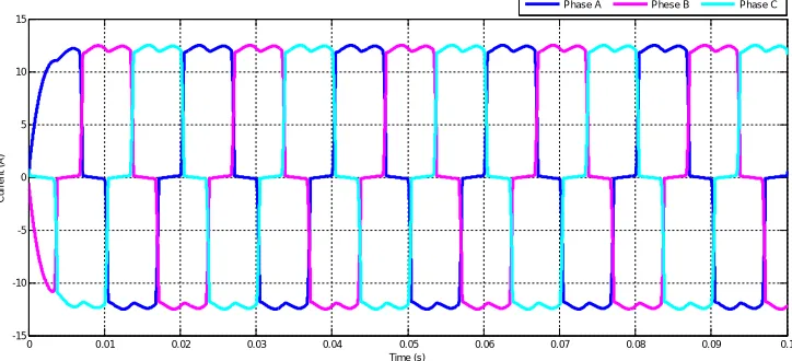
Fig. 3. Current waveform without UPQC due to nonlinear load.
Fig. 4. Current waveform after using PI based UPQC
0 0.01 0.02 0.03 0.04 0.05 0.06 0.07 0.08 0.09 0.1
-15 -10 -5 0 5 10 15 Time (s) C u rr e n t (A )
Phase A Phese B Phase C
0 0.01 0.02 0.03 0.04 0.05 0.06 0.07 0.08 0.09 0.1
-25 -20 -15 -10 -5 0 5 10 15 20 25 Time (s) C u rr e n t (A )
Fig. 5. Current waveform after using Fuzzy Logic Based UPQC
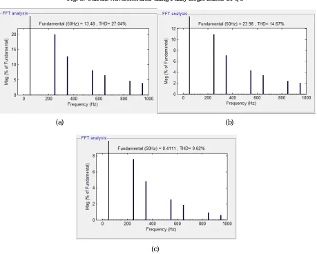
(a) (b)
(c)
Fig. 6. Harmonic content in current waveform (a) Harmonic content in current without UPQC (b) Harmonic content in current after using PI based UPQC (c) Harmonic content in current after using Fuzzy Logic based UPQC.
0 0.01 0.02 0.03 0.04 0.05 0.06 0.07 0.08 0.09 0.1
-0.5 -0.4 -0.3 -0.2 -0.1 0 0.1 0.2 0.3 0.4 0.5
Time (s)
C
u
rr
e
n
t
(A
)
From the above results we found that, when the system is subjected to nonlinear loads then we can see current harmonics found is about 27.04% which is highly undesirable. The current harmonics is then reduced by using PI based UPQC to 14.67% and the harmonics is further reduced by using fuzzy logic based UPQC to about 9.62% which is acceptable.
V.CONCLUSION
As shown in Fig. 4 is the comparative results of the performance of PI based and Fuzzy logic based UPQC. The PI based was able to reduce harmonics in the current to about 14.67% as compared to Fuzzy logic based UPQC that is about 9.62% and from these results we can conclude that Fuzzy logic based UPQC produces the best results.
REFERENCES
[1] L. Gyugyi, “Unified power flow control concept for flexible ac transmission systems,” Proc. IEE, Pt. C, Vol. 139, pp. 323–331,Google Scholar 1992.
[2] H. Akagi, Y. Kanazawa, A. Nabae , “Generalized Theory of the Instantaneous Reactive Power in Three Phase Circuits”, in Proc. IPEC-Tokyo’83 Int. Conf. Power Electronics, Tokyo, pp. 1375- 1386, 1986.
[3] V. Khadkikar, P. Aganval, A. Chandra, “A Simple New Control Technique for Unified Power Quality Conditioner (UPQC)”, 11th International Conference on Harmonics and Quality of Power 2004.
[4] I.Axente, M.Basu and M.Conlon, “dc link voltage control of UPQC for better dynamic performance”, Electric Power Systems Research 81, 1815–1824, 2011.
[5] Jain S. K., Agrawal P. and Gupta H. O., “Fuzzy logic controlled shunt active power filter for power quality improvement,” IEE Proc. Electr. Power Appl., vol. 149, no. 5, pp. 317-328, 2002.
[6] D. C. Bhonsle, R. B. Kelkar, “Design and Simulation of Single Phase Shunt Active Power Filter”, International Conference on Recent Advancements in Electrical, Electronics and Control Engineering, 2011.
[7] V. Khadkikar, P. Aganval, A. Chandra, “ A Simple New Control Technique For Unified Power Quality Conditioner (UPQC)”, 11th International Conference on Harmonics and Quality of Power, 2004.
[8] H. Akagi, E. H. Watanabe, M. Aredes, Instantaneous Power Theory and Applications to Power Conditioning, New Jersey: IEEE Press / Wiley-Interscience, ISBN: 978-0-470-10761-4. http://www.wiley.com/WileyCDA/WileyTitle/productCd-047011892X.html. 2007.
[9] R.V.D.Rama Rao & Subhransu Sekhar Dash “Design of UPQC with Minimization of DC Link voltage for the Improvement of Power Quality by Fuzzy Logic Controller”, ACEEE International Journal on Electrical and Power Engineering, Vol. 02, No. 01, pp. 36-42, Feb 2011. [10] Sathakkathulla.S and Kumarasabapathy.N “Power Quality Improvement using Fuzzy Logic based UPQC”, International Conference on