Emission Reduction using Magnetic Pollution
Filter
Mr.Prof.Bhokre N. M 1, Mohit A. Bagul 2, Nilesh S. Boddawar 3, Yogesh S.Tuptewar 4 Senior Lecturer, Dept. of Mechanical Engineering, Govt Polytechnic Aurangabad, Maharashtra, India1
U.G. Student, Department of Mechanical Engineering, D.Y.P.I.E.T, Pimpri, Pune, Maharashtra, India 2,3,4
ABSTRACT: The purpose of Magnetic Pollution filter is to reduce the emissions of automobile engines such as petrol and diesel engines. In this project the neodium magnets having intensity of 9000 gauss are placed over the periphery of conventional silencer. The magnetic field around periphery of conventional silencer is created and ionization takes place. This changes the forms of hydrocarbon and other pollutants. It was found that percentage of exhaust gas component (CO & HC) in case of diesel engine is decreased by 47%, 2% respectively, and 82%, 94% in case of petrol engines. In this way the emissions can be reduced in large extent, this is one of the emission reduction technique with low cost.
KEYWORDS: Magnetic field, Fuel Gas Analyzer, Emission Control, Neodium magnet etc.
1. INTRODUCTION
The Internal Combustions Engine generates undesirable emissions which directly affects on living entities and causes different health problems, one of the biggest environmental problems facing the world today is atmospheric pollution. While some air pollution can be traced to natural causes, it is presently believed that a large portion of air pollution is produced by human activities and more specifically, by burning of fossil fuel, garbage, recyclable materials and so on. Some progress has been made in reducing the production of pollutants. For example, cars and other vehicles using internal combustion engine are now equipped with catalytic converters. These converters are formed of honeycombed materials constructed and arranged to restrict the flow of exhaust gases along predetermined paths while these gases are exposed to catalytic materials based usually of rhodium and palladium. In this both C.I and S.I are equally responsible, most fuels do not combust until they are vaporized and mixed with air. Emission of motor vehicle consists of unburned hydrocarbons and oxides of nitrogen react in atmosphere and create smog. Each fuel molecules contain magnetic property having positive and negative charges. However these molecules have not been realigned, the fuel is not actively interlocked with oxygen during combustion, the fuel molecule or hydrocarbon chain must be ionized and realigned. The ionization and realignment is achieved through the application of magnetic field.
In this project, uniform magnetic field was created around the periphery of conventional silencer with uniform mountings of magnets on the surface of conventional silencer so that uniform results will be obtained in the performance test of engine. Generally catalytic convertor is used to control over the emission of automobile engines but it has few disadvantages such as the material is rarely found and costly.
II. LITERARATURE SURVEY
Author Saban Akyildiz, Harrison, NY (US) designed a system which helps to reduce the pollution of power generating devices such as automobiles, Industrial chimneys etc. the electromagnetic field is generated around the periphery of silencer. As the exhaust from engine is passed through the silencer the ionization takes place inside the exhaust chamber as a combination of heat and magnetic field. The exhaust pollutants inside the silencer start burning and we get the clean exhaust at the outlet of engine. The designed of system is so simple so that it is suitable for any kind of application. The cost of the system is low compare with the conventional methods used for reducing the emission. [6]
Jackson, H., McArthur, D., and Simpson, H., have been evaluated Hundreds of catalysts in bench activity tests, using synthetic engine exhaust gas to determine conversion of NO to N₂ and NH₃. Many of these catalysts were also exposed to actual engine exhaust in an engine-dynamometer test, and then re-evaluated in the bench apparatus to determine the degree of catalyst deactivation. For catalysts prepared on nonreactive, hydrothermally stable support materials, it was found that the primary causes of deactivation were sulfur and lead poisoning. Subsequently, it was determined that deactivation of a NOx catalyst from sustained exposure to engine exhaust can be closely simulated by impregnating the fresh catalyst with lead acetate to the required lead level, followed by testing the catalyst with SO₂
present in the synthetic exhaust gas. These studies have resulted in the development of catalysts showing high initial NOx conversion efficiency and little deactivation in engine tests. [5]
III. EXPERIMENTAL SET UP
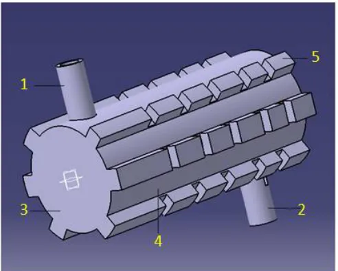
The effect of magnetic field on exhaust emission of automobile engines can be examined by this method. Experimental set up shows following diagram drawn in Catia Software.
Figure 1: Primary Layout of System
Following numbering shows part involved in the system; 1-Intake of Exhaust,
2- Outlet of Exhaust,
3-Exhaust Chamber, 4- Magnetic Field around periphery of silencer, 5- Position of Magnet
The above primary layout shown is drawn in the modeling software Catia V5 for proper visualization of the proposed system. It gives the basic idea about the concept i.e. magnetic pollution filter. The following materials and equipment is used;
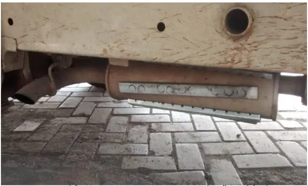
3.1 Neodium Magnets
The neodium type of magnets is used to create magnetic field. The magnet has capacity of 9000 gauss and can sustain the temperature up to 300o C which is more than sufficient as exhaust temperature of automobile engines is around 80o C to 90o C. To obtain the uniform results the magnetic strip is manufacture as shown;
Figure 2: Magnetic Strip
The method of arc welding was used to manufacture the magnetic strip; it has the uniform number of slots for producing proper magnetic field around the periphery of silencer.
3.2 Testing Procedure
The standard procedure which is proposed by the ARAI, Pune, India is used to perform the test. The same procedure is followed for both types of engines as follows;
1. Start the engine and keep idle for 15 minutes.
2. Take the reading without applying the system by using standard gas analyzer.
3. Now turned off the engine, apply the magnetic strips around the periphery of conventional silencer. 4. Again start the engine and keep idle for 15 minutes.
5. Take the readings and compare the results.
3.3 Engine
The test is performed on two types of engine such as petrol and diesel engine. The petrol engine of single cylinder four stroke having maximum power @7500 rpm is 8 bhp. The diesel engine of four cylinder four stroke with 16 hp maximum power @3200 rpm is used for performing the test.
3.4 Test and Measurement Equipment
Pollution under control (PUC): Under Rule 115(7) of Central Motor Vehicle Rules (CMVR), 1989, motor vehicles are required to carry PUC Certificate to be a given by an agency authorized for this purpose by State Govt. Measurement of emissions from petrol vehicle is done by gas analyzer and in case of diesel vehicle emission is measured by smoke meters. There is a list of approved vendors and models of PUC equipment which is compiled and circulated by ARAI, Pune.
IV.EXPERIMENTAL RESULTS
The tests on vehicle are carried out in normal condition excluding the factors such as periodic maintenance of vehicle, condition of engine etc. The test is conducted on two types of engine such as diesel and petrol, the result analysis as follows;
4.1 Four cylinder four stroke Diesel engine. (Tata Ace)
After test it is found that, large variation in the CO up to 47% and in case of HC it is reduced up to 2%.
Sr. No. Gas Without system With System Percentage
01 CO 18 % vol. 9.4 % vol. 47% decrease
02 HC 971 ppm vol. 960 ppm vol. 2% decrease
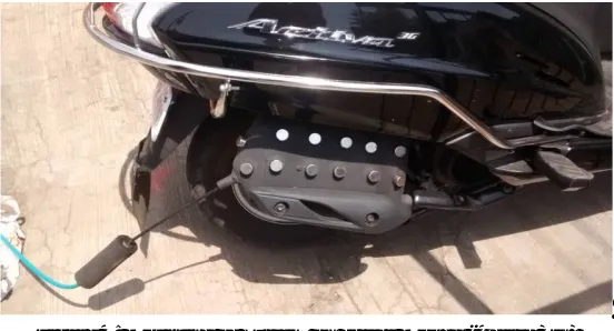
4.2 Single cylinder four stroke Petrol engine. (Activa 3G)
The test were taken on the Activa 3G, firstly the engine is cranked and kept on idle for 15 min. Then the readings were taken by gas analyser and turned off the engine. Now the magnets were placed over the periphery of silencer after the gap of 10min. Again the engine is cranked and readings were noted, it is found that, variation in the CO is up to 10% and in case of HC it is reduced up to 58%
Figure 4: Mounting of System on actual Moped (Activa 3G)
Without System With System
The following table shows the results of Activa 3G before applying the magnets and after mounting of magnets, it is observed that more changes in the results.
Sr. No. Gas Without system With System Percentage
01 CO 0.20 % vol. 0.18 % vol. 10% decrease
02 HC 64 ppm vol. 27 ppm vol. 58% decrease
03 CO2 2.30 % vol. 2.0 % vol. 13% decrease
In this test three parameters are checked simultaneously such as CO, HC, CO2, firstly the readings were noted without applying the system at idling condition of vehicle without carrying any load on it, after some time the same process is followed with applying the magnets to generate the magnetic field for reducing the pollution, it is found that moderate variation in the results.
4.3 Comparison of Results
a) Effect of magnetic field on Carbon monoxide
The graph shows the percentage of carbon monoxide in case of petrol and diesel engine,
0 5 10 15 20
CO(Tata Ace) CO(Activa 3G)
C
O
in
%
V
o
l. Without System
b) Effect of Magnetic field on Hydrocarbons
The graph shows the percentage of Hydrocarbon in case of petrol and diesel engine,
V.CONCLUSION
1. The smoke value obtained before applying the system is higher but after applying the magnetic pollution filter it is reduced up to large extent.
2. CO in exhaust is decreased up to 47 % to 10 % in case of diesel and petrol engine respectively 3. HC in exhaust is decreased up to 2 % to 58 % in case of diesel and petrol engine respectively
4. To generate magnetic field is economically feasible as it does not required any external source of energy.
REFERENCES
[1] Ali S. faris et.al, “Effects of Magnetic Field on Fuel consumption and exhaust emissions in two stroke engine”, Energy Procedia, Vol.18, pp.327-338, 2012.
[2] Karthik Dhayakar, G. Vijay, J. et.al, “Effect of Twin Sparkplug in Two Stroke IC Engine”, International Journal of Science and Research (IJSR),Vol.4,pp.2147-2153, 2015.
[3] Adel Mahmmod Salih, Abdul-Rahman Mutez Ahmed, “The effect of magnetic field on the boiler performance fueled with diesel”, International Journal of scientific & Engg. Research (IJSER), Vol.7, pp.406-410, 2016.
[4] Jackson, H., McArthur, D., and Simpson, H., “Catalytic NOx Reduction Studies”, SAE Technical Paper, 730568, 1973, doi: 10.4271/730568. [5] Saban Akyildiz, Harrison, “Magnetic Pollution Filter”, Pub. N0: US 2002/0053283 A1, Pub. Date: May 9, 2002.
0 200 400 600 800 1000 1200
HC(Tata Ace) HC(Activa 3G)
H
C
in
p
p
m