High Efficient Sign detector for Residue Number System
Meer Amer Ali
1, D. Divya Reddy
21
M.Tech (DSCE),
2Assistant Professor (ECE), Sri Visvesvaraya Institute of Technology & Science,
Chowderpally, Devarkadra, Mahabubnagar
ABSTRACT
The moduli set {2n − 1, 2n, 2n + 1} has been commonly used in residue number system (RNS)-based
calcula-tions. Its sign extraction problem, even though fundamentally important in magnitude comparison and other
difficult algorithms in RNS, has received considerably less attention than its scaling and reverse conversion
problems. This paper presents a new algorithm for the design of a fast adder-based sign detector. The circuit is
greatly simplified by minimizing the dynamic range to eliminate large modulo operations with the help of the
new Chinese remainder theorem. Our synthesis results show that the proposed design outperforms all the
exist-ing adder-based sign detectors reported for this moduli set in area and speed.
Keywords:
Chinese remainder theorem (CRT), computer arithmetic, residue number system (RNS).
I.
NTRODUCTION
Residue number system (RNS) is gaining enhancing popularity in the VLSI implementation of
application-specific digital signal processors (DSPs). This is in part due to its ability to accelerate and to decrease the power
consumptions of crucial and frequently used data path operations by subword-level parallelism and modularity,
and in part due to the ease of realizing modulo operations using the moduli of the forms 2n and 2n±1. Modular
2n±1. arithmetic properties have been exploited with arithmetic structures, such as diminished-1, sparse carry
chain, Kogge–Stone adder, and so on, to decrease the implementation complexity of modulo addition,
subtrac-tion, and multiplication for these special moduli to an extent that is comparable with their two’s complement
number system counterparts. These improvements have given rise to the extensive use and continual successes
in developing the balanced three moduli set {2n − 1, 2n, 2n + 1} for the implementation of many new and
exist-ing DSP algorithms, includexist-ing fast Fourier transform, discrete wavelet transform, finite and infinite impulse
response filters, and digital image processing. In fact, the difficulties associated with the implementation of
nonmodular operations, such as scaling and reverse conversion from residue-to-binary representation, have
largely been resolved for this three moduli set.
Even though the hardware efficiency of its individual residue arithmetic operations, as well as its forward and
reverse converters, some fundamental operations, such as sign detection, magnitude comparison, and overflow
detection, for this moduli set remain slow and expensive. These operations are complicated to parallelize as they
need the combination of multiple residue values to calcilate. To reduce the computational complexity, lookup
tables are often used to store the precalculated orthogonal projections of the numbers of interest. Unfortunately,
memory-based ways are difficult to pipeline. The size and number of lookup tables, as well as their access time
problem for this moduli set. Despite its importance as a preprocessing operation and an integral component of
other intermodulo operations like magnitude comparison and overflow detection, only a handful of solutions are
found in the literature.
A general theorem for sign detection in residue domain is presented, where the magnitude of an integer is first
decoded from its residue representations by converting the residues into its equivalent binary representation to
find the halfway point of the dynamic range. The large modulo operation in the reverse conversion is decreased
by the mixed radix conversion (MRC) and to a modulo-two sum by using the fractional binary representation.
Both the implementations are based on ROMs, which suffer from the aforementioned deficiencies. The most
recent RNS sign detectors were designed for {2n − 1, 2n, 2n+1 − 1}. Although very efficient standalone, its use is
limited as the efficient reverse converter, and scaler needed for a complete system implementation has not been
reported for this new moduli set. The only adder-based sign detection circuits for {2n −1, 2n, 2n +1} identify the
sign by either full or partial reverse conversion into the binary domain using the new Chinese remainder
theo-rem, or through the mixed radix coefficients.
In this paper, an alternative efficient sign detection algorithm for {2n−1, 2n, 2n+1} is proposed. The proposed
technique develops the new CRT-I to greatly simplify the 22n − 1 scaling of residue representation into addends
that can be readily achieveed by circular left shifted residues at no logic cost. The reduced dynamic range
enables the sign of an integer to be calculated directly from the most significant bit (MSB) of the scaled residues
with a heavily strippeddown version of a reverse converter. Another benefit of our proposed sign detector is that
it can also be used as a scaler.
II. PRELIMINARIES AND NOTATIONS
RNS is characterized by a set of N coprime numbers, called the moduli set {m1, m2, . . . ,mN }, i.e., GCD(mi ,m
j ) = 1∀i ≠ j . Any integer X can be represented by an N-tuple (x1, x2, . . . , xN ) in this moduli set. Each residue
xi is the least nonnegative remainder calculated by dividing X by the modulus mi , which can be expressed
ma-thematically as xi = |X|mi for i = 1, 2, . . . , N. The product of all moduli is called the dynamic range M, i.e., M =
_N i=1 mi . Any integer X that lies within 0 ≤ X < M will have a unique residue representation.
An integer X within the dynamic range can be recovered from its residue representation (x1, x2, . . . ,
xN ) by applying the CRT
……(1)
where Mi = M/mi and |M−1i |mi is the multiplicative inverse
of |Mi |mi .
To represent a signed integer Xˆ in RNS, M is divided into two symmetrical half ranges for the representation of
positive and negative integers. When M is even, the range of signed integers that can be definitely represented in
RNS is [−M/2, M/2 − 1]. Correspondingly, for odd M, the range of definitely representable signed integers in
RNS is [−(M − 1)/2, (M − 1)/2]. The signed integer Xˆ can be represented using the same residue representation as an unsigned integer X for the same moduli set. The relationship between Xˆ and X is given as follows:
When Xˆ ≥ 0, the residue representation of X can be mapped to that of Xˆ in the range of [0, M/2 − 1] if M is
even and [0, (M − 1)/2] if M is odd. In a similar way, when Xˆ < 0, the residue representation of X can be
mapped to that of Xˆ in the range of [M/2, M − 1] if M is even and [(M + 1)/2, M − 1] if M is odd. Thus, the sign of Xˆ can be identified as follows.
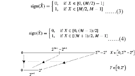
When M is even
……(3)
When M is odd
……(4)
Fig. 1. Mapping of the half ranges of integer X in [0, M) to the half ranges of its scaled integer Y in [0, M')
Properties 1 and 2 are employed in order to simplify some arithmetic operations in the derivation of our
pro-posed sign detection circuit for RNS {2n − 1, 2n, 2n + 1}.
Property 1: The modulo 2n − 1 multiplication of an n-bit binary number x and r exponent of two is equivalent to
a circular left shift (CLS) of the binary bits of x by r positions
……(5)
where CLSn(x, r ) represents the circular shift of an n-bit binary number x by r bits to the left.
Property 2: As a corollary of Property 1
……(6) Where −x is the one’s complement of integer x.
III. PROPOSED SIGN DETECTION ALGORITHM
Let (x1, x2, x3) be the residue representation of an integer X with respect to the moduli set {m1, m2, m3} = {2n − 1,
2n, 2n + 1}. Since the dynamic range M of this moduli set can be factored into 2n and 22n − 1, the sizes of the
modulo operations required for identifying the sign of Xˆ from its equivalent residue representation of X can be
substantially decreased by scaling (x1, x2, x3) in the residue domain by 22n − 1. This will map thes lower half
range [0, 23n−1 − 2n−1) of X to the lower half range [0, 2n−1) of the scaled integer Y and the upper half range [23n−1
− 2n−1, 23n − 2n) of X to the upper half range [2n−1, 2n) of Y , as shown in Fig. 1. By minimizing the dynamic
range from M = 23n − 22n to M' = 2n, its half range can be easily identified from the MSB of the scaled integer Y.
This new concept of sign detection in {2n −1, 2n, 2n +1} can be made very efficient provided that scaling by 22n
− 1 as well as the reverse conversion of the scaled residues into Y can be computed efficiently from the residues
x1, x2, and x3. As only the MSB of Y is needed for the sign detection of Xˆ , a full reverse conversion from (x1, x2,
x3) is not needed.
……(7)
where k1m3 = |1|m1m2 and k2m3m1 = |1|m2 .
With m1 = 2n−1, m2 = 2n, and m3 = 2n + 1, we have
……(8)
It can be proved that the multiplicative inverses of |2n + 1|2n (2n−1) and |22n − 1|2n are given by k1 = 22n−1 − (2n
− 1) and k2 = −1, respectively. These closed form expressions of k1 and k2 are proved as follows.
Proof of k1 = 22n−1 − (2n − 1):
k1(2n + 1)|2n (2n−1) = |[22n−1 − (2n − 1)](2n + 1)|2n (2n−1)
= |22n−1(2n + 1) − (22n − 1)|2n (2n−1)
= |23n−1 − 22n−1 + 1|2n (2n−1)
= |22n−1(2n − 1) + 1|2n (2n−1) = 1.
Proof of k2 = −1:
Substituting the values of k1 and k2 into (8), we have
……(9)
By scaling X by 22n −1, the scaled integer Y can be obtained by
……(10)
where Z = |22n−1(x1 − x3) − (2n − 1)(x2 − x3)|2n(2n−1).
Since x3∈ [0, 2n ], x3 < 22n − 1. Therefore [(x3/22n − 1)] = 0, and Y can be written as
……(11)
As [(|x|m1m2 /m1)] = |[(x/m1)]|m2 from [11], (11) can be rewritten as
……(12)
Let H = 22n−1(x1 − x3). Since H = m[(H/m)] + |H|m for any integer H and m, we have
……(13) Taking mod 2n operation on both the sides of (13), we have
……(14)
……(15)
Substituting (15) into (12), we have
……(16)
If Y ∈ [0, 2n−1), X falls in the lower half range of M and (x1, x2, x3) denotes a positive integer, i.e., Xˆ ≥ 0.
Other-wise, if Y ∈ [2n−1, 2n), X falls in the upper half range of M and (x1, x2, x3) represents a negative integer, i.e., Xˆ <
0.
3.1 HARDWARE IMPLEMENTATIONS
The residues x1, x2, and x3 can be denoted in a binary form as x1 = x1,n−1x1,n−2 . . . x1,0, x2 = x2,n−1x2,n−2 . . . x2,0 and
x3 = x3,n x3,n−1 . . . x3,0, respectively, where xi, j represents the j th bit of the residue xi . The binary vectors of x1
and x2 are of n bits but the binary vector of x3 is of n + 1 bits. In (16), one of the terms in the modulo 2n − 1 sum
involves the operation |−22n−1 x3|2n−1, which cannot be directly implemented by Property 2, since x3 has n+1
bits. To apply the CLS property on the one’s complement of x3 as in (6), x3 is expressed as x3 = 2nx3,n +
x3,n−1x3,n−2 . . . x3,0. Since |2n x3,n|2n−1 = x3,n, the MSB x3,n of x3 can be logically OR with x3,0 to form an n-bit
binary vector x'3 = |x3|2n−1 = |x3,n−1x3,n−2 . . . x'3,0|2n−1, where x'3,0 = x3,0∨x3,n and ∨ denotes a logical OR operator.
|H|2n−1 in (16) can then be implemented using the CLS operations of Properties 1 and 2 to obtain
……(17)
where
……(18)
……(19)
The term |u1 + u2|2
n−1 can be expressed as
……(20)
Fig. 3. Example of the generation of the carry signal C
1and v for n = 8
Hence, ||u1 + u2|2n−1|2n = |u1 + u2 + cin|2n, where cin ∈ {0, 1}. As |−x2|2n = 2n − x2 =  ̄x2 + 1, (17) can be written
as
……(21)
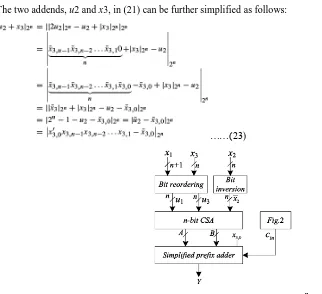
The generation of the carry-in signal cin is shown in Fig. 2. The
condition u1 +u2 ≥ 2n is detected by C1 = 1 and the signal C1 can be generated by parallel prefix operators. As an
example, the carry signal C1 for n = 8 can be generated by the circuit shown in Fig. 3. The condition u1+u2 =
2n−1 = {11 . . . 11}n can be identified by C2 = 1. C2 is generated by  ̄w ∧ v, where w = ∧i=0
n−1
gi and v = pn−1:0
= ∧i=0n−1 pi, where ∧ denotes a logical AND operator. The signals gi and pn−1:0 have already been generated in
the computation of C1. Accordingly, the condition u1+u2 ≥ 2n −1 for cin = 1 can be detected by
cin = C1∨ C2……(22)
The two addends, u2 and x3, in (21) can be further simplified as follows:
……(23)
When x3,n = 0, x'3,0 = x3,0∨ 0 = x3,0. Then (24)
When x3,n = 1, since x3∈ [0, 2n], x3,n−1x3,n−2 . . . x3,0 = 00 . . . 0. Hence, x'3,0 = x3,0∨ x3,n = 1 and
……(25)
To satisfy both (24) and (25)
……(26)
where the n-bit binary vector u3 is given by
……(27) Substituting (26) into (21), we have
……(28)
If x3,0 = 1, 1 −  ̄x3,0 = 1, and if x3,0 = 0, 1 −  ̄x3,0 = 0. Hence, the term 1−  ̄x3,0 in (28) can be replaced by x3,0
and
……(29)
The sign of Xˆ can be identified by the MSB of Y. An n-bit carry save adder (CSA) can be used to add the three
n-bit operands, u1, u3, and  ̄x2, to produce an n-bit sum A = an−1an−2 . . . a0 and an n-bit carry vector B = bn−1bn−2
. . . b1b0. Due to the modulo 2n addition, the final carry output bit bn of the CSA need not be generated. As b0 =
0, it can be replaced by x3,0 of (29) before the MSB of Y is calculated by a simplified parallel prefix adder of A
and B with the input carry bit c−1 = cin. The prefix adder is simplified by keeping only the carry generation
net-work for the computation of carry signal cn−1, from which the sign of Xˆ can be identified by
. The architecture of the proposed sign detector is shown in Fig. 4, where the
circuit diagram for the simplified prefix adder is depicted in Fig. 5 for n = 8.
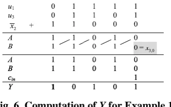
Fig. 6. Computation of Y for Example 1
Example 1: For n = 5, {m1, m2, m3} = {31, 32, 33}, M = 31 × 32 × 33 = 32 736, and M/2 = 16 368. The signed
integer Xˆ = −11 161 can be denoted by the residue representation (x1, x2, x3) = (30, 7, 26) according to the
un-signed integer X = 21 575 in the same moduli set. The binary representation of the residues are x1 = 111102, x2 =
001112, and x3 = 0110102. According to (18), (19), and (27), u1 = 011112, u2 = 100102, and u3 = 011012. Also,
x3,0 = 0. Since u1 + u2 = 01111 + 10010 = 33 > 32, C1 = 1. Since 33 _= 31, C2 = 0. According to (22), cin = C1∨
C2 = 1. The calculation of Y in (29) is illustrated in Fig. 6. Since MSB of Y = 1, the integer Xˆ represented by
(30, 7, 26) is negative.
IV. SYNTHESIS AND SIMULATION RESULTS
The proposed razor latch is designed with the XILINX ISE 14.5 simulation tool and implemented with Verilog
HDL. The RTL diagram and simulation results are displayed below.
Fig: Top level schematic diagram
Fig: Synthesis report
Fig: Simulation result
VI. CONCLUSION
In this paper, an efficient fast sign detection algorithm for the residue number system moduli set {2n-1, 2n,2n+1}
is presented. The proposed algorithm which allows parallel implementation and include modulo 2n additions.
Based on existing sign detection algorithm, an efficient sign detection algorithm is proposed. The sign detection
unit can be implemented using one carry save adder, one comparator and one prefix adder. Here efficiency
achieved is better than other algorithm for sign detection. Adder based sign detectorwas designed by the Verilog
HDL synthesized in Xilinx ISE 14.5.
VII. FUTURE SCOPE
Arithmetic designs are developed and holded with these proposed methods of reverse converters in RNS
formu-lation. Finally with these conditional procure positions of adders obtain the eventual levels of area, power and
performance.
REFERENCES
[1] R. Muralidharan and C.-H. Chang, “Area-power efficient modulo 2n −1 and modulo 2n + 1 multipliers
for {2n − 1, 2n, 2n + 1} based RNS,” IEEE Trans. Circuits Syst. I, Reg. Papers, vol. 59, no. 10, pp.
2263–2274, Oct. 2012.
[2] H. T. Vergos and G. Dimitrakopoulos, “On modulo 2n+1 adder design,” IEEE Trans. Comput., vol. 61,
[3] H. T. Vergos, “A family of area-time efficient modulo 2n +1 adders,” in Proc. IEEE Comput. Soc. Annu.
Symp. VLSI, Lixouri, Kefalonia, Greece, Jul. 2010, pp. 442–443.
[4] L.-S. Didier and L. Jaulmes, “Fast modulo 2n−1 and 2n+1 adder using carry-chain on FPGA,” in Proc.
Asilomar Conf. Signals, Syst., Comput., Pacific Grove, CA, USA, Nov. 2013, pp. 1155–1159.
[5] N. S. Szabó and R. I. Tanaka, Residue Arithmetic and Its Applications to Computer Technology. New
York, NY, USA: McGraw-Hill, 1967.
[6] R. Conway and J. Nelson, “Improved RNS FIR filter architectures,” IEEE Trans. Circuits Syst. II, Exp.
Briefs, vol. 51, no. 1, pp. 26–28, Jan. 2004.
[7] E. Vassalos, D. Bakalis, and H. T. Vergos, “RNS assisted image filtering and edge detection,” in Proc.
IEEE 18th Int. Conf. Digit. Signal Process., Fira, Santorini, Greece, Jul. 2013, pp. 1–6.
[8] J.-C. Bajard, L.-S. Didier, and T. Hilaire, “ρ-direct form transposed and residue number systems for
fil-ter implementations,” in Proc. IEEE 54thInt. Midwest Symp. Circuits Syst., Seoul, Korea, Aug. 2011,
pp. 1–4.
[9] Y. Liu and E. M.-K. Lai, “Design and implementation of an RNS-based 2-D DWT processor,” IEEE
Trans. Consum. Electron., vol. 50, no. 1, pp. 376–385, Feb. 2004.
[10] T. F. Tay, C.-H. Chang, and J. Y. S. Low, “Efficient VLSI implementation of 2n scaling of signed
in-teger in RNS {2n−1, 2n, 2n+1},” IEEE Trans. Very Large Scale Integr. (VLSI) Syst., vol. 21, no. 10, pp.
1936–1940, Oct. 2013.
AUTHOR DETAILS
MEER AMER ALI, pursuing M.Tech (DSCE) from Sri Visvesvaraya Institute Of
Tech-nology & Science, Chowderpally (Vill), Devarkadra (Mdl), Mahabubnagar (Dist), TS,
IN-DIA.
D. DIVYA REDDY, working as Assistant professor (ECE) from Sri Visvesvaraya Institute
Of Technology & Science, Chowderpally (Vill), Devarkadra (Mdl), Mahabu nagar (Dist),